Abstract
The ability to harness the processes by which complex tissues arise during embryonic development would improve the ability to engineer complex tissuelike constructs in vitro—a longstanding goal of tissue engineering and regenerative medicine. In embryos, uniform populations of stem cells are exposed to spatial gradients of diffusible extracellular signaling proteins, known as morphogens. Varying levels of these signaling proteins induce stem cells to differentiate into distinct cell types at different positions along the gradient, thus creating spatially patterned tissues. Here, the authors describe two straightforward and easy-to-adopt microfluidic strategies to expose human pluripotent stem cells in vitro to spatial gradients of desired differentiation-inducing extracellular signals. Both approaches afford a high degree of control over the distribution of extracellular signals, while preserving the viability of the cultured stem cells. The first microfluidic platform is commercially available and entails static culture, whereas the second microfluidic platform requires fabrication and dynamic fluid exchange. In each platform, the authors first computationally modeled the spatial distribution of differentiation-inducing extracellular signals. Then, the authors used each platform to expose human pluripotent stem cells to a gradient of these signals (in this case, inducing a cell type known as the primitive streak), resulting in a regionalized culture with differentiated primitive streak cells predominately localized on one side and undifferentiated stem cells at the other side of the device. By combining this approach with a fluorescent reporter for differentiated cells and live-cell fluorescence imaging, the authors characterized the spatial and temporal dynamics of primitive streak differentiation within the induced signaling gradients. Microfluidic approaches to create precisely controlled morphogen gradients will add to the stem cell and developmental biology toolkit, and may eventually pave the way to create increasingly spatially patterned tissuelike constructs in vitro.
I. INTRODUCTION
A marvel of embryonic development is how uniform populations of stem cells give rise to spatially patterned tissues comprising multiple types of cells. How is this starting uniformity broken, thus generating complex spatial patterns and tissues? A tenet of developmental biology is that within the embryo, stem cells are exposed to spatial gradients of diffusible extracellular signaling molecules termed morphogens. Graded levels of such signals instruct stem cells to differentiate into distinct cell types in a concentration-dependent manner, consequently instructing the generation of different types of cells at different positions along the morphogen gradient.1,2 However, all of these events occur within the intricate confines of the developing embryo. Due to experimental constraints in obtaining and manipulating embryos, many outstanding questions continue to surround the morphogen model. Except in favorable circumstances,3,4 it has been challenging to either visualize or quantitatively manipulate morphogen gradients in vivo to test whether these parameters quantitatively affect the spatial pattern of the final tissue. Most significantly, it is unclear whether morphogen gradients are sufficient to create a spatially patterned tissue. While morphogen gradients clearly exist in vivo,5 it is unclear whether they are the decisive forces that pattern tissues or whether alternate mechanisms could have equally important roles. To answer this question, it is of paramount importance to artificially create morphogen gradients in vitro6,7 and to test whether they are sufficient to create patterned tissuelike structures in a reductionist culture system. However, many technical hurdles must first be addressed, and overcoming some of these hurdles is the subject of this report.
Our goals were to artificially create morphogen gradients outside of the embryo and to assess whether they could cause colonies of pluripotent stem cells to differentiate into biologically appropriate cell types in a spatially controlled way. To create our model culture system, we employ human pluripotent stem cells (hPSCs), which include both embryonic stem cells8 and induced pluripotent stem cells9 and have the potential to develop into all of the different cell types in the human body. The differentiation of hPSCs into various cell types can be guided by extracellular signaling molecules, but thus far the vast majority of attempts to differentiate hPSCs either harness spontaneously produced signals from the cells themselves (e.g., in so-called “embryoid bodies” or “organoids”) or have relied on the spatially uniform application of external signaling molecules.10–12 Although a number of previous studies have shown that certain differentiation-inducing signals have concentration-dependent effects on hPSCs (i.e., gut tube13 or central nervous system14 patterning), these approaches often added different levels of a signaling molecule in different wells of a culture plate (i.e., in discrete conditions) and did not create a true spatial gradient within a single well.
Engineering a stable and continuous morphogen gradient across hPSCs could enable precise spatial control over hPSC differentiation in vitro, as occurs in vivo. To that end, microfluidics constitute a set of technologies for manipulating small volumes of fluids within submillimeter channels15 that have been used to exact an unprecedented level of control over the physical and chemical microenvironment of living cells.16,17 Microfluidic cell culture platforms offer additional advantages over traditional cell culture such as automation, high throughput analysis capabilities,18 low reagent consumption, and the creation of more physiologically relevant environments for cells by continuous perfusion culture or the imposition of biologically relevant chemical gradients.19,20
While microfluidic channels were originally fabricated from glass and silicon,21 replica molding using the optically transparent elastomer polydimethylsiloxane (PDMS)22 has become the standard for microfluidic fabrication in academic laboratories.20 PDMS-based microfluidics offer low cost per device, rapid fabrication, biocompatibility, and gas permeability. Templates for replica molding are typically fabricated by photolithography,23 but 3D-printed24 and laser-cut templates25 are gaining popularity.26
There are two broad classes of microfluidics for generating chemical gradients: static and flow-based systems. In static gradient-generating microfluidics, a flow barrier such as a membrane, hydrogel, or microchannel minimizes convection between two reservoirs of fluid at different concentrations, creating a gradient by passive diffusion.23 Flow-based gradient-generating microfluidics take advantage of the low Reynolds number flow conditions in microchannels, where gradients are generated by diffusive mixing between two or more laminar fluid streams of different concentrations, flowing parallel to one another.27 Design of the gradient profiles is versatile,23 with multiple inlets providing a greater degree of control over the resulting gradient.28 The simplest configuration of flow-based microfluidics for generating a gradient is the Y-channel, comprising two inlets and a single outlet.
The use of laminar flow to spatially pattern cell colonies in a microfluidic cell culture channel was first demonstrated by Takayama et al.16 Numerous microfluidic cell culture platforms followed, including several platforms developed specifically for stem cell biology.18,29,30 Y-channel microfluidics, for example, were used to alter the relative rate of development of two halves of a Drosophila embryo via a temperature gradient31 and to induce differentiation across only half of an embryoid body via a morphogen gradient.32 More recent microfluidic systems designed to apply gradients to stem cell cultures have employed a combination of laminar flow and flow barriers to maintain a stable gradient across stem cells, while shielding the cells from shear stress.6,7
Despite an explosion of microfluidic “lab-on-chip” cell culture platforms of increasing throughput and sophistication,33,34 microfluidic technologies have not been widely adopted by mainstream biology.20 While decades of effort have gone into optimizing macroscale cell culture protocols, these methods do not necessarily translate into microfluidic culture, where the substrate material and the ratio of media volume to number of cells are altered.19 Procedures for functional coating of microchannels, optimal cell seeding densities, and cell feeding schedules must all be customized to each individual cell type and microfluidic device environment.19 Furthermore, control over microfluidic systems may require external pumps and tubing. Replication of published high resolution, multiplexed, or multilayer35 microfluidics may pose a challenge for labs that do not have access to or familiarity with cleanroom technologies. Simpler microfluidic designs, such as the Y-channel, however, do not necessarily require cleanroom fabrication,24 and disposable static gradient-generating microfluidic systems that do not require pumping systems have recently become commercially available.20 Thus, the utility of microfluidics in basic biological research is likely hindered by a perceived requirement for complex device design, fabrication, and operation.
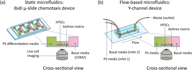
Here, we implement and characterize two widely accessible microfluidic platforms for generating morphogen gradients across cell cultures to exact spatial control over stem cell differentiation (see Fig. 1). First, we developed a protocol for regionalizing stem cell differentiation using a commercially available chemotaxis chamber (Ibidi)36,37 to apply static morphogen gradients across hPSCs. Second, we achieved regionalized cell cultures with morphogen gradients generated by flow-based, single-layer Y-channel microfluidics. In the latter devices, we found that we could program the steepness of the gradient by adjusting the flow rates; however, cell morphology and cell adhesion to the substrate were compromised by wall shear stresses accompanying the flow of media. We used comsol multiphysics numerical simulation to model the distribution and dynamics of proteins and small molecules in the primitive streak differentiation media across the cell culture channels in each microfluidic platform. Combining a primitive streak reporter cell line with live cell imaging, we were able to record the spatial and temporal dynamics of stem cell identity under this morphogen gradient.
FIG. 1.
Schematic of microfluidic setups used to generate gradients of soluble signaling factors across MIXL1-GFP hPSCs. Cells undergoing differentiation into anterior primitive streak (PS) were observed with live-cell fluorescence microscopy. (a) Static Ibidi -slide chemotaxis microfluidic device. (b) Flow-based Y-channel polydimethylsiloxane (PDMS) microfluidic device.
II. EXPERIMENT
A. Pluripotent stem cell culture
The MIXL1-GFP reporter cell line developed by Davis et al. was chosen because its GFP expression is compatible with live cell imaging, and the MIXL1-GFP expression in this cell line has been shown to mirror expression of primitive streak genes MIXL1 and BRACHYURY.11,38 MIXL1-GFP hPSCs were maintained in feeder-free conditions using mTeSR1 media (StemCell Technologies 85850). Cells were cultured on tissue culture plastic coated with Geltrex basement matrix (ThermoFisher A1413302) diluted 1:100 in DMEM/F12 media (Gibco 10565042). Cells were passaged to desired density before reaching confluency using Versene (Gibco 15040066). The cell line was determined to be mycoplasma free and karyotypically normal prior to differentiation.
B. Stem cell differentiation in static microfluidics
Commercially available chemotaxis chambers (Ibiditreat -slide Chemotaxis chambers, Ibidi 80326) were used to establish and maintain an approximately static, linear gradient of morphogens across the hPSCs during primitive streak induction. These microfluidic devices were originally designed for visualization of mammalian cell chemotaxis (directed migration) in response to a chemical gradient.36,37 Each disposable device arrives in sterile packaging, is comprised of a plastic chip the size of a microscope slide (), and contains three separate cell culture chambers supplied with media by larger triangular chambers at either end of the chamber [see Fig. 1(a)]. Media was introduced to the chambers by manual pipetting.
Prior to cell seeding, microfluidic channels were coated with Geltrex diluted 1:100 in DMEM/F12 media, rinsed with DMEM/F12, and maintained at and 5% overnight. For cell seeding, hPSCs were dissociated using Accutase (ThermoFisher 00-4555-56), resuspended to cells per ml in mTeSR1 with ROCK inhibitor Thiazovivin (TZV, Tocris 3845), and filtered through a cell strainer (Bel-Art H136800040). Using a beveled pipet tip, of cell suspension were added to the top of a filling port for the central channel of each Ibidi -slide Chemotaxis chamber, and the channel was filled by aspirating the cell suspension from the opposite port. The device was covered and placed in a 10-cm Petri dish with Kimwipes moistened with UltraPure Water (Invitrogen 10-977-023). The hPSCs were allowed to adhere to the matrix overnight at and . Cells were maintained in the device with daily media changes to the central channel using mTeSR1 without TZV until desired confluency was reached.
Primitive streak induction was performed as in Loh et al., with the exception that PI3K inhibitor was omitted.11 For basal media, chemically defined media 2 (CDM2) was used, which consisted of the following components: 50% IMDM (Gibco 31980-097), F12 (Gibco 31765-092), polyvinyl alcohol (Sigma P8136-250G), concentrated lipids (Gibco 11905-031), monothioglycerol (Sigma M6145), insulin (Roche 1376497), transferrin (Roche 652202), and penicillin/streptomycin (Gibco 15140163). For the primitive streak media, 40 ng/ml BMP4 (R&D Systems 314-BP-050), CHIR99021 (WNT agonist; Tocris 4423), 20 ng/ml FGF2 (R&D Systems 233-FB-01M), and 30 ng/ml activin A ( agonist; R&D Systems 338-AC-050) were added to CDM2.
Prior to primitive streak induction in the cell colonies on the left side of the cell culture chamber, the central chamber was rinsed twice with of CDM2 to remove any cell debris. Following this, of CDM2 were added to each side channel by direct injection with a pipet. Finally, () of CDM2 in the left chamber were replaced with primitive streak induction media at double the required concentration, such that the final concentration in the left chamber matched that of the primitive streak media described above.
C. Fabrication of Y-channel microfluidics
Designs for Y-channel microfluidic devices were generated using AutoCAD software and printed on transparency masks (CAD/Art Services, Inc.). A channel width of 2 mm was selected to allow assembly of several healthy hPSC colonies within the channel, and a channel length of 17 mm was selected to ensure fully developed laminar flow. To create templates for replica molding, polished silicon wafers were cleaned in acetone, methanol, and isopropanol and dried in under a stream of nitrogen gas. After 5 min on a hotplate, the wafers were spin-coated with photoresist (SU-8 100, MicroChem Corp.) at 3000 rpm for 30 s. The following day, the wafers were soft baked for 10 min at , 30 min at , and exposed using a mask aligner (Quintel). They were then baked for 1 min at , 10 min at , and developed for 10 min in SU-8 developer (MicroChem Corp.). The wafers were rinsed in isopropanol and dried under a stream of gas. Finally, wafers were hard baked at for 20 min and treated with a trimethylchlorosilane (TMCS) vapor (Sigma-Aldrich M85301) to facilitate demolding after PDMS casting.
To fabricate the microchannels, 46.2 g of PDMS (Sylgard 184) was mixed at a 10:1 ratio of silicone base to crosslinker and degassed for 30 min. This mixture was poured onto the silicon mold and degassed for an additional 15 min. The PDMS was cured at for 2 h then carefully removed from the mold. Devices were cut, and two inlets and one outlet per device were created with a 1 mm biopsy punch (Integra Milltex 3331AA). Devices were autoclaved in Milli-Q water for a 20 min liquid cycle at (Getinge), removed from water, and allowed to dry in a sterile container at . Each device was bonded to a No. 1.5 coverglass (Fisher 22266882) following oxygen plasma activation (March Instruments) at 80 W for 20 s. Finally, bonded devices were autoclaved in a 20 min cycle with a 20 min drying step at . Following this, devices were sterile and ready for use [see Fig. 1(b)].
Prior to cell seeding, channels were coated by injecting of 1:100 Geltrex in DMEM/F12 into the outlet port using a bevelled pipet tip. The device was left for 1 h at room temperature, then rinsed with of DMEM/F12 and allowed to incubate at and 5% overnight.
Three sets of polyethylene tubing (Scientific Commodities Inc. BB31695-PE/2) were prepared per Y-channel device. Tubing was connected to a 27G flat end Luer-lock needle (McMaster-Carr M929) and sterilized by flowing through a minimum of 1 ml each of 70% ethanol, sterile Milli-Q water, and phosphate buffered saline (PBS, Gibco 10010023).
D. Stem cell differentiation in Y-channel microfluidics
of hPSC suspension at cells per ml were injected into each Y-channel device, and cells were left to adhere overnight at and 5% . Prior to stem cell differentiation, channels were rinsed twice with of CDM2 to remove any cell debris.
Approximately 2 ml of primitive streak differentiation media or basal CDM2 media were added to each 3 ml Luer-lock syringe (BD 309657), and each syringe was connected to sterile tubing. For inlet tubing, cell culture medium was pumped through until a droplet appeared at the tip, then all inlet tubing was backfilled with of CDM2 to delay CHIR99021 exposure until the start of the experiment. Inlet and outlet tubing were connected to each device, taking care to prevent the formation of air gaps. To induce primitive streak in the top half of the cell channel, tubing containing primitive streak differentiation media was connected to the top inlet, while tubing containing the basal media, CDM2, was connected to the bottom inlet.
Flow rates were controlled using a syringe pump (Chemyx Fusion 200 Touch with expansion rack). Infusion rates of 500 nl/min and 100 nl/min at the inlets were used as high and low flow rate conditions, respectively. The withdrawal rate at the outlet was set to double the input rate at the inlets.
E. Imaging
Epifluorescence imaging was performed on an inverted Nikon Ti-E microscope (Nikon, Minato, Tokyo, Japan) equipped with a Heliophor light engine (89 North) and an Andor sCMOS Neo camera using a Plan Apo Lambda air objective lens.
Live cell imaging of microfluidic channels containing hPSCs was performed in conditions compatible with cell culture (, ). For Y-channel devices, flow was initiated immediately prior to image acquisition. Images were acquired every 60 min for cells in static devices and every 30 min in flow-based devices for up to 24 h.
F. Gradient profile modeling
Distributions of extracellular signals in the Ibidi chemotaxis chambers were modeled using comsol multiphysics numerical simulations. For proteins, the reported molecular weight as determined by SDS-PAGE in nonreducing conditions was used. Hydrodynamic radius was estimated by assuming an average protein density of and determining the minimum radius required to contain the mass of the protein molecule.39 To estimate the diffusion coefficient for CHIR99021, the Stokes–Einstein equation was used.40 To estimate the diffusion coefficient for proteins, an empirical correlation derived by He et al. was used.40 Parameters can be found in Table I. For all simulations, ambient temperature was set to , and the physical properties of water were assumed, with the exception of viscosity, where that of cell culture media was used ( at ).41 The models did not take into account chemical degradation or morphogen-morphogen interactions.
TABLE I.
Diffusion constants used in comsol simulations of morphogen gradients.
| Molecular weight | Diffusion constant | |
|---|---|---|
| Extracellular signal | (kDa) | (m2/s) |
| CHIR99021 | 0.47 | 5.99 × 10⁻¹⁰ |
| BMP4 | 40 | 6.94 × 10⁻¹¹ |
| FGF2 | 16.5 | 9.26 × 10⁻¹¹ |
| Activin A | 24 | 8.23 × 10⁻¹¹ |
For numerical simulations of the morphogen gradient in the static Ibidi microfluidic devices, the side and cell chamber geometries of the Ibidi device were rendered in 3D. No-flux boundary conditions were applied to all surfaces except the interfaces between the side chambers and central cell chamber. An initial concentration condition for all extracellular signals in the primitive streak differentiation media was set for the left chamber, while all other regions had an initial concentration of zero for all species. A time-dependent simulation for transport of dilute species was performed for 0–24 h with a time step of 0.5 h, as well as for 0–30 min with a time step of 5 min.
For numerical simulations in the Y-channel microfluidic devices, the inlets, channel, and outlets were rendered in 3D. For transport of dilute species, no-flux boundary conditions were applied to all surfaces except the inlets and outlets. A concentration condition was applied to each inlet, with the top inlet having the concentration of the species in the differentiation medium and the bottom inlet having a concentration of zero. An initial concentration condition of zero for all extracellular signals was set for the entire geometry. For creeping flow, a no slip boundary condition was set for all walls, the flow rate of interest was set at each inlet as fully developed flow, and a zero-pressure and backflow suppression condition was applied to the outlet. A stationary simulation for transport of dilute species and creeping flow was performed for flow rates of 0.1, 0.01, 0.001, and 0.0001 ml/min for CHIR99021 as well as for flow rates of 500 and 100 nl/min for all species, to correspond to rates used in cell differentiation experiments.
Distribution of CHIR99021 across cell culture channels in each microfluidic platform was simulated experimentally with a fluorescent small molecule of similar molecular weight and observed with time-lapse inverted fluorescence microscopy. In the Y-channel microfluidic device, a aqueous solution of the fluorescent molecule tetramethylrhodamine-5-(and-6)-isothiocyanate [5(6)-TRITC](TMR) (Thermofisher T490) in PBS was pumped into one of two inlets of the microfluidic channel, while PBS was pumped into the other inlet to generate a gradient across the channel. In the Ibidi chemotaxis device, all three chambers were filled with PBS, then of PBS from the left reservoir were replaced with of TMR to create a solution of TMR in the left reservoir and a gradient across the central chamber.
III. RESULTS AND DISCUSSION
A. Distribution of extracellular signals as a function of time in static microfluidics
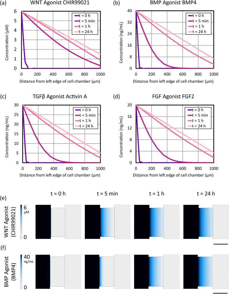
Primitive streak differentiation entails four major extracellular signals: the proteins Activin, BMP4 and FGF2 (which respectively activate the , BMP and FGF signaling pathways) and the small molecule CHIR99021 (which activates the WNT signaling pathway).11 We computationally modeled the distribution of these differentiation-inducing signaling molecules within our microfluidic platforms, thus defining the shape and slope of our artificial morphogen gradients. Concentration gradient profiles in static microfluidics as calculated by comsol numerical simulation are shown in Fig. 2. Time points of 0 h, 5 min, 1 h, and 24 h were chosen to highlight temporal differences in gradient establishment between the extracellular signals. Notably, the linear concentration gradient is established on the order of minutes for small molecule WNT agonist CHIR99021, as compared to the time scale of approximately an hour for the extracellular protein signals.
FIG. 2.
comsol multiphysics numerical simulation of extracellular signal concentrations across the cell culture chamber in the Ibidi static microfluidic device. (a)–(d) Graphs of the distribution of primitive streak (PS) soluble signaling factors in the Ibidi static microfluidic device. (e) and (f) Comparison of the establishment of the gradient between small molecule WNT agonist CHIR99021 and protein BMP4, where the color map indicates the concentration of the respective morphogen. The center rectangle depicts a top-down view of the central cell chamber. Scale bar: 1 mm.
In agreement with the device characterization performed by Ibidi, the linear gradient is maintained over the course of 24 h, although the right edge of the cell chamber reaches approximately 20% of the differentiation media concentration for all species by the end of this time period. These simulation results were confirmed experimentally using time-lapse fluorescence imaging of TMR in the Ibidi chemotaxis device (Videos 1a and 1b of the supplementary material45). Thus, for differentiation protocols that require approximately 24 h, such as primitive streak induction per Loh et al.,10 the Ibidi static microfluidic device provides a user-friendly and medium-throughput platform for maintaining a linear gradient for stem cell differentiation. Longer differentiation protocols, however, may require manual media changes to maintain a stable gradient. In addition, because stem cells are known to respond to morphogens in a concentration-dependent manner,18 time-varying gradients such as this one may result in cell exposure to different morphogen concentrations than desired.
B. On-chip spatially controlled primitive streak induction in static microfluidics
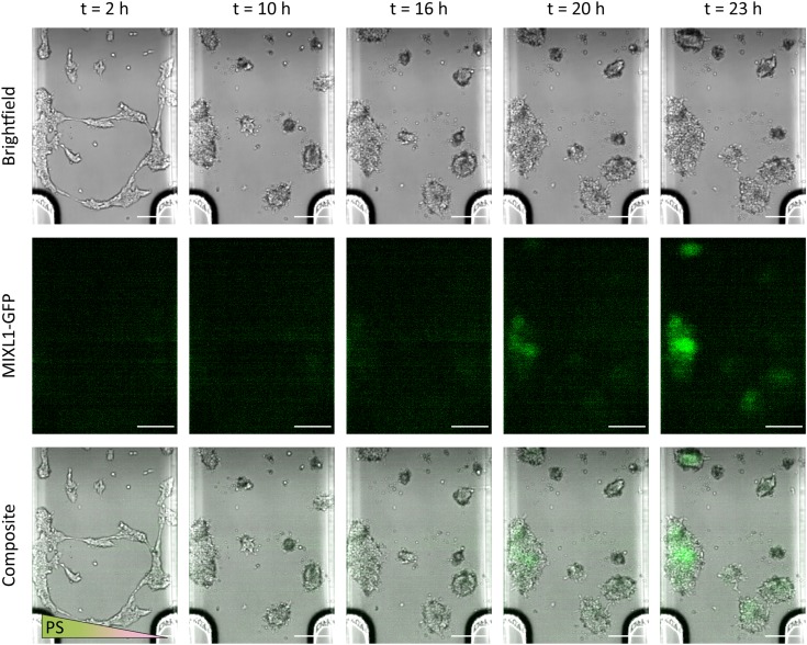
We observed the successful induction of primitive streak, as indicated by MIXL1-GFP expression,10,11,38 in the left half of the cell culture chamber in the static Ibidi microfluidic device (see Fig. 3 and Video 2 of the supplementary material45). On this side, the hPSCs were exposed to higher concentrations of extracellular primitive streak signals over the course of 24 h. Initially, the cells displayed a contractile phenotype upon exposure to CHIR99021 but recovered and spread over the course of several hours. Initial MIXL1-GFP expression can be seen between and , and this signal is clearly established by . This repeatable result () provides a proof-of-concept for the utility of gradient-generating static microfluidic devices for the spatial patterning of stem cell differentiation. Such devices do not require specialized knowledge or access to fabrication facilities as they are commercially available, nor do they require accessory equipment such as pumps and tubing. In addition, multiple experiments can be performed in parallel, making it a potentially high-throughput technique (especially in the absence of live-imaging). However, as indicated by our model, the cell colonies at the right side are also exposed to a nonzero concentration of soluble signaling factors by and begin to exhibit weak MIXL1-GFP expression (see Fig. 3).
FIG. 3.
Time-lapse bright-field and fluorescence imaging of primitive streak (PS) induction in MIXL1-GFP hPSCs in a static Ibidi microfluidic device. Differentiation in cell colonies begins on the left side of the cell culture chamber due to the higher concentration of primitive streak-inducing signals. Cell morphology changes over time in response to CHIR99021 exposure. Fluorescent green (GFP) indicates MIXL1 expression and thus the induction of primitive streak. Scale bar: .
A major advantage of microfluidic devices over standard cell culture techniques for stem cell differentiation is the precise spatial control of morphogens in a regime where diffusive transport plays a dominant role.18 Here, the Ibidi chemotaxis device takes advantage of a large height difference between the central and side chambers to generate a nearly linear concentration gradient. The dynamics of this gradient were confirmed for our model system using comsol multiphysics numerical simulation, although the presence of a monolayer of cells at the bottom of the chamber would present a small deviation from ideal conditions.
C. Distribution of extracellular signals as a function of flow rate in flow-based microfluidics
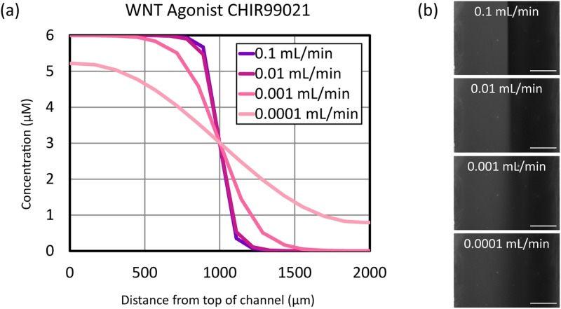
We predicted and observed a flow rate dependence in the distribution of small molecules across the channel for chemical gradients generated using y-channel microfluidics (see Fig. 4). Experimentally, at higher flow rates, a steeper gradient was observed at the boundary of the two streams, whereas the decrease in TMR concentration across the channel was more gradual at low flow rates [see Fig. 4(b)]. The TMR gradient was constant with time after initial stabilization on the order of seconds, and the resulting gradients were spatially reproducible and predictable unless bubbles formed in the channel. The COMSOL model indicated that increasing the flow rate above 0.01 ml/min had a minimal effect on the gradient profile, but there is more variation in steepness as a function of flow rate in the low flow rate regime. Thus, Y-channel devices offer more options of gradient profile in the flow regime that is most relevant to stem cell culture due to the condition of low shear stress.18
FIG. 4.
Concentration profiles of extracellular signals vary as a function of flow rate in Y-channel microfluidic devices. (a) COMSOL simulation of a gradient of the small molecule WNT agonist CHIR99021 at various flow rates. (b) TMR concentration gradient profiles as a function of flow rate in a 2 mm wide Y-channel microfluidic device. The gradient appears sharper as the flow rate in the channel is increased. In micrographs at right, TMR appears gray, PBS appears black. Scale bar: .
While not explored in this study, gradients generated in Y-channel microfluidics can also be spatially positioned by varying the relative flow rates of the inlet streams,16 which along with varying flow rate provides an additional degree of tunability as compared to a static commercial device.
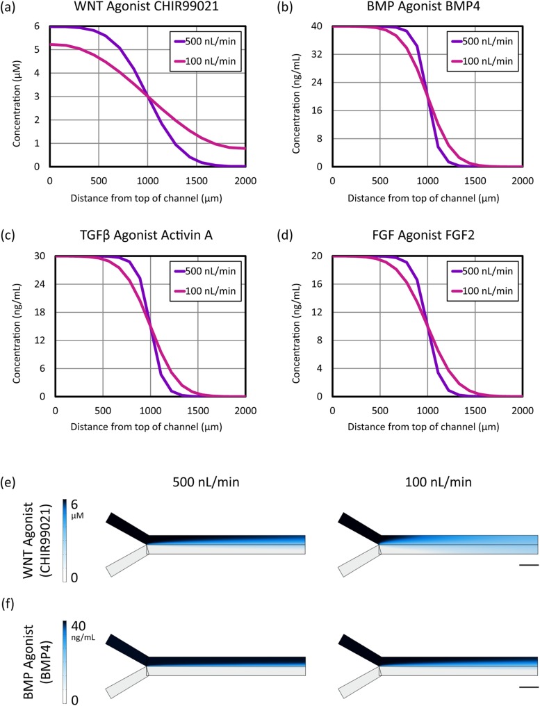
Steady-state concentration gradient profiles in flow-based Y-channel microfluidics as calculated by COMSOL finite element simulations are shown in Fig. 5. Values are plotted along a path from the top to the bottom of the channel at a position from the left edge, where the two inlet streams meet. Flow rates of 500 nl/min and 100 nl/min were simulated to correspond to the flow rates we used in stem cell differentiation experiments. Due to the differences in diffusion constants, and as predicted,16 the gradients in protein molecule concentration were steeper than those of CHIR99021, a small molecule.
FIG. 5.
comsol finite element simulation of extracellular signal concentrations across the cell culture chamber as a function of flow rate in a 2 mm wide Y-channel microfluidic device. (a)–(d) Distribution of primitive streak (PS) soluble signaling factors across the channel at a position 2 mm to the right of the Y-junction along the length of the channel at flow rates of 500 and 100 nl/min. (e) and (f) Comparison of steady-state gradient profiles for the small molecule WNT agonist CHIR99021 and the protein BMP4. Color map indicates the concentration of the respective morphogen. Direction of flow is left to right. Scale bar: 2 mm.
In addition, it is important to note that the gradient varies as a function of distance along the channel [see Figs. 5(e) and 5(f)], such that cells closer to the inlet streams will be exposed to a sharper spatial gradient than those further downstream (closer to the outlet). Depending on how sensitive the cells are to the relative levels of extracellular signals used to generate primitive streak, these differences may create patterns of differentiation along the microchannel, an effect that may be useful or undesirable depending on the context of the particular experiment.
D. On-chip spatially controlled primitive streak induction in flow-based microfluidics
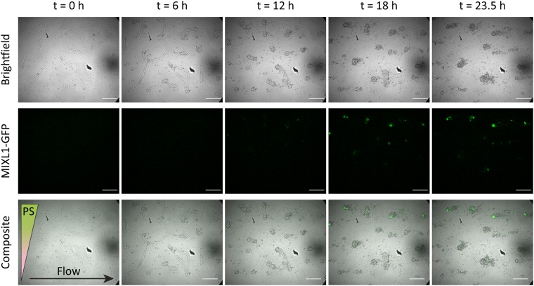
Primitive streak induction was successfully performed in the upper half of a 2 mm wide Y-channel microfluidic device with a flow rate of 100 nl/min per inlet () (see Fig. 6 and Video 3 of the supplementary material45). Initially, as in the static devices, cell contraction was observed when the cells were first exposed to CHIR99021. During this process, some cells delaminated and were swept away by the flow of media. The same behavior can be observed in a control experiment where CDM2 basal media without primitive streak factors was pumped through the channel (, data not shown). However, a sufficient number of cell colonies remains such that MIXL1-GFP is expressed by , indicating the induction of primitive streak. By , these primitive streak cell colonies persisted (see Fig. 7), demonstrating spatially controlled differentiation of hPSCs despite the detrimental effects of shear stress. Unlike in the static device, the bottom half of the cell colonies are exposed to a morphogen concentration of zero throughout the duration of the experiment. In addition, flow experiments conducted with and without live imaging show the same result at the end point of (see Figs. 6 and 7).
FIG. 6.
Time-lapse bright-field and fluorescence micrographs of MIXL1-GFP hPSCs exposed to a gradient of anterior primitive streak (PS) factors in a flow-based Y-channel microfluidic device. The flow rate at each inlet is 100 nl/min, and the direction of flow is from left to right. Cell morphology changes over time in response to CHIR99021 exposure, and fluorescent green (GFP) indicates MIXL1 expression and thus the induction of primitive streak. Scale bar: .
FIG. 7.
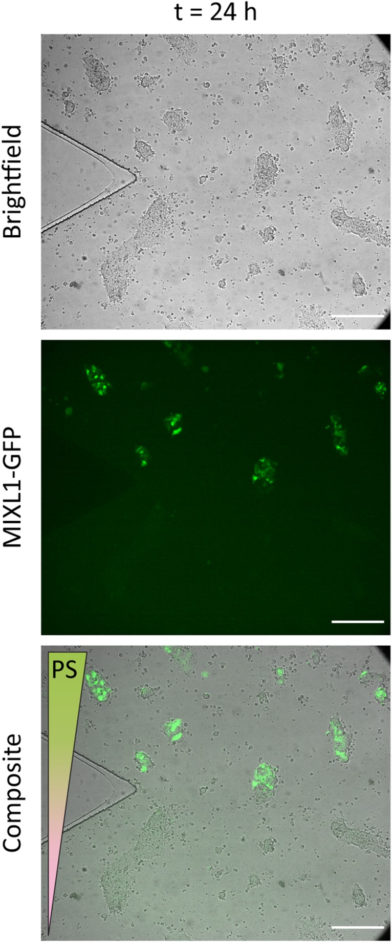
Bright-field and fluorescence micrographs of MIXL1-GFP hPSCs after 24 h of exposure to a gradient of anterior primitive streak (PS) factors in a flow-based Y-channel microfluidic device in the vicinity of the Y-junction. Flow rate at each inlet was 100 nl/min. Fluorescent green (GFP) indicates MIXL1 expression and thus the induction of primitive streak in the hPSCs in the upper half of the channel. Scale bar: .
When this experiment was performed at a higher flow rate of 500 nl/min at each inlet (Video 4 of the supplementray material45), the cells experienced extensive delamination (), and by , no cell matter was detected in the cell culture channel. A basal media control at this flow rate also showed extensive cell delamination with no cell matter detected during postflow imaging (), indicating the sensitivity of hPSC-matrix adhesion to fluid shear stress even in the absence of primitive streak factors (data not shown). Thus, despite tighter control of the gradient profile and the temporal stability of the gradient, tunability of the concentration profile in flow-based microfluidics is limited by the maximum shear stress that the cells can withstand. It may be possible to increase the adhesion strength of cells cultured in the Y-channel microfluidics by increasing the concentration of Geltrex adsorbed to the glass coverslip.42
A summary of our comparison of easily implemented static and dynamic microfluidic platforms for spatial control over stem cell differentiation can be found in Table II. Several challenges to the use of Y-channel microfluidics as presented in this study are worth noting. While careful operation precluded the need for additional microfluidic accessories such as bubble traps, implementing Y-channel microfluidics for regionalized stem cell differentiation did require experimental expertise. In addition, operation of a single microfluidic Y-channel required three syringes, meaning that syringe pump capacity limits experimental throughput. Finally, the shear stress associated with even our low flow rate condition adversely affected hPSC adhesion, providing motivation for increasing flow-based device complexity at the cost of simplicity of fabrication and operation.6,7 Alternatively, hPSC adhesion could potentially be improved in the Y-channel devices through surface functionalization of the glass-bottom channel or increasing the concentration of the Geltrex coating.43
TABLE II.
Comparison of static and flow-based microfluidic devices for stem cell differentiation.
| Static microfluidics | Flow-based microfluidics | ||
|---|---|---|---|
| Advantages | Disadvantages | Advantages | Disadvantages |
| External pumps and tubing not required | Gradient changes with time and stabilizes on a time scale of hours | Gradient constant with time and stabilizes within seconds to minutes | External pumps and tubing required |
| Commercially available (no operational or fabrication expertise required) | Single option for gradient profile | Tunable control of gradient profile using channel geometry and/or flow rate(s) | Requires operational expertise and access to a fabrication facility |
| No shear stress on cells | Manual media changes via pipetting required | Media changes on cells are automated | Shear stress can disrupt cell-matrix adhesion |
| Easily parallelizable | Throughput limited by pump capacity | ||
| Preserves autocrine and paracrine signals secreted by cells | Bubbles may arise during flow and disrupt gradient | ||
A final fundamental difference between static and dynamic microfluidic platforms for stem cell differentiation is that with static microfluidics, autocrine and paracrine signals secreted by cells are preserved, whereas these are constantly replaced by external factors in dynamic, flow-based platforms.44 We did not observe any spatial and temporal differences between the static and dynamic platforms we employed to regionalize primitive streak induction, but by implementing both, one could potentially decouple externally applied signals from signals secreted by the cells themselves in culture.
IV. CONCLUSION
Prevailing approaches largely attempt to differentiate cultures of stem cells into uniform populations of a single cell type.12 However, the ability to precisely and reproducibly generate stem cell-derived differentiated cultures wherein multiple cell types are present, and organized in a spatially defined way, constitutes an important step forward in the generation of increasingly realistic tissuelike constructs. To that end, microfluidics have been used to generate spatial gradients of differentiation-inducing signals,6,7 but multiple challenges remain, most notably ease of fabrication and operation.
We have taken two complementary microfluidic approaches to expose hPSCs to spatial gradients of differentiation-inducing signals. We have also computationally modeled the spatial distribution of such signals in these microfluidic devices as a function of time and flow rate. First, we used commercial chemotaxis chambers to generate gradients of primitive streak-inducing signals in hPSC cultures and show that this method reproducibly generates differentiated primitive streak progenitors predominately localized on one side of the culture. Of particular importance, these static microfluidics have the potential to be widely adopted as tools by biologists and engineers as they are commercially available and require no specialized equipment or expertise.
Second, we used a flow-based Y-channel microfluidic gradient to induce primitive streak in a spatially controlled manner across hPSC colonies; however, the shear stresses that accompanied the flow of media resulted in changes to cell morphology as well as cell delamination. This loss of adherent cells occurred earlier and more significantly at higher flow rates. Despite their incompatibility with primitive streak induction, Y-channel microfluidics offer a high degree and more tunable control over a temporally stable gradient may be compatible with other stages of stem cell differentiation.
ACKNOWLEDGMENTS
The authors wish to thank members of the Loh, Dunn, Ang, and Fordyce labs for helpful advice and discussion. Part of this work was performed at the Stanford Nano Shared Facilities (SNSF), supported by the National Science Foundation (NSF) under Award No. ECCS-1542152. This work was supported by the California Institute for Regenerative Medicine (ARD, Grant No. RB4-06102), the Stanford EDGE Fellowship, the Stanford Bio-X Bowes Fellowship, the Stanford ChEM-H Chemistry/Biology Interface Predoctoral Training Program, and the National Institute of General Medical Sciences of the National Institutes of Health under Award No. T32GM120007 (K.W.C.), a Stanford ChEM-H Postdoctoral fellowship (L.E.), and the Stanford Graduate Fellowship (C.E.D.). Partial support for this project was provided by the Stanford RISE Program (T.C.N.). K.M.L. is a Packard Foundation Fellow, Pew Scholar, Human Frontier Science Program Young Investigator and The Anthony DiGenova Endowed Faculty Scholar. The content is solely the responsibility of the authors and does not necessarily represent the official views of the National Institutes of Health.
Biographies
 Kiara W. Cui is a Ph.D. candidate in Chemical Engineering at Stanford University in the labs of Alexander Dunn and Gerald Fuller. Her research interests lie at the intersection of fluid mechanics and biological systems, and she is excited about the potential of such research to help us better understand human disease and development. Kiara received her BS in Chemical Engineering from MIT and is currently supported by the Stanford Chemistry, Engineering, and Medicine for Human Health (ChEM-H) at the Chemical-Biological Interface (CBI) Training Program, the Stanford Bio-X Bowes Fellowship, and the Stanford Enhancing Diversity in Graduate Education (EDGE) Fellowship.
 Leeya Engel is a postdoctoral research fellow in the Department of Chemical Engineering at Stanford University, working at the interface of microfabrication and mammalian cell biology. She received a BSc in physics from The Hebrew University of Jerusalem, Israel in 2008 and her M.Sc. and Ph.D. in materials engineering and nanotechnologies in 2014 and 2016 from the Tel Aviv University, Israel. Dr. Engel’s doctoral work focused on developing electroactive polymer micro-actuators and innovating microfabrication methodologies for polymer microsystems and was recognized by a number of research awards including the AVS Nellie Yeoh Whetten Award and the NA’AMAT Israel Award for Women in Engineering Sciences. Dr. Engel was the founding president of the student chapters of the Materials Research Society (MRS) and the Israel Vacuum Society (IVS) at Tel Aviv University. She launched and co-chaired an annual national graduate student conference (with attendees). Following a grant from the Sackler Fund for Convergence Research in Biomedical, Physical and Engineering Sciences, Dr. Engel worked as a visiting student researcher integrating printed electronics and electroactive polymers with microfluidics in the Lin lab at UC Berkeley. Dr. Engel began her postdoctoral training in the Pruitt, Dunn, and Weis labs at Stanford after she was awarded a Stanford CHEM-H Postdoctoral Fellowship for Interdisciplinary Postdoctoral Training in Quantitative Mechanobiology in 2016. In the Pruitt lab, Dr. Engel was trained in experimental biology, fabrication, and functionalization of bio-MEMS. She pioneered the use of maskless photopatterning to control cell position on EM grids for whole cell cryo-electron microscopy. In the Dunn lab, Dr. Engel has been engineering microfluidic platforms for stem cell culture and performing cryo-electron tomography on endothelial cells cultured on microfabricated substrates to study the subcellular organization at cell–cell junctions. She has published 12 papers, holds two patents, and her career goal is to pursue a faculty position following her post doctorate. Her future lab will use engineering tools to modify the microenvironment of the cell to answer questions in mechanobiology.
 Carolyn E. Dundes is a Ph.D. candidate in Stem Cell Biology & Regenerative Medicine at Stanford University in the lab of Kyle Loh. Their work at Stanford is primarily focused on better understanding how to model early human brain development using pluripotent stem cells. In collaboration with the Dunn Lab, they applied their knowledge of human embryonic stem cell differentiation strategies to spatially pattern primitive streak development in vitro. Carolyn received their BA in Biology from Wesleyan University and is currently supported by the Stanford Graduate Fellowship.
 Tina C. Nguyen is a senior at Andrew P. Hill High School. She has a passion to express her creativity through building projects in the Mathematics, Engineering, Science, Achievement (MESA) Program, getting excited when her ideas jump from paper to reality. As the president of her school’s American Red Cross Club, she spends most of her free time volunteering. She pursued her interests by participating in Stanford’s Future Advancers of Science and Technology (FAST) Program and in the Raising Interest in Science and Engineering (RISE) Internship. She plans to study biomechanical engineering after high school.
 Kyle M. Loh is an Assistant Professor and The Anthony DiGenova Endowed Faculty Scholar at Stanford School of Medicine. He is captivated by the challenge of how we can precisely differentiate human pluripotent stem cells into desired types of cells. Microfluidic signaling gradients could add a new dimension to stem-cell differentiation efforts by affording spatial control over the differentiation process, thus creating spatially patterned differentiated cell populations. Kyle is a Packard Fellow, Pew Scholar, Human Frontier Science Program Young Investigator and Baxter Foundation Faculty Scholar and has been recognized by the NIH Director’s Early Independence Award and Forbes 30 Under 30.
Note: This paper is part of the Special Topic Collection on 30 years of the Nellie Yeoh Whetten Award — Celebrating the Women of the AVS.
Contributor Information
Kiara W. Cui, Email: .
Leeya Engel, Email: .
Kyle M. Loh, Email: .
Alexander R. Dunn, Email: .
REFERENCES
- 1.Rogers K. W. and Schier A. F., Annu. Rev. Cell Dev. Biol. 27, 377 (2011). 10.1146/annurev-cellbio-092910-154148 [DOI] [PubMed] [Google Scholar]
- 2.Briscoe J. and Small S., Development 142, 3996 (2015). 10.1242/dev.129452 [DOI] [PMC free article] [PubMed] [Google Scholar]
- 3.Shimozono S., Iimura T., Kitaguchi T., Higashijima S.-i., and Miyawaki A., Nature 496, 363 (2013). 10.1038/nature12037 [DOI] [PubMed] [Google Scholar]
- 4.Yu S. R., Burkhardt M., Nowak M., Ries J., Petrášek Z., Scholpp S., Schwille P., and Brand M., Nature 461, 533 (2009). 10.1038/nature08391 [DOI] [PubMed] [Google Scholar]
- 5.Zagorski M., Tabata Y., Brandenberg N., Lutolf M. P., Tkačik G., Bollenbach T., Briscoe J., and Kicheva A., Science 356, 1379 (2017). 10.1126/science.aam5887 [DOI] [PMC free article] [PubMed] [Google Scholar]
- 6.Demers C. J., Soundararajan P., Chennampally P., Cox G. A., Briscoe J., Collins S. D., and Smith R. L., Development 143, 1884 (2016). 10.1242/dev.126847 [DOI] [PMC free article] [PubMed] [Google Scholar]
- 7.Manfrin A., Tabata Y., Paquet E. R., Vuaridel A. R., Rivest F. R., Naef F., and Lutolf M. P., Nat. Methods 16, 640 (2019). 10.1038/s41592-019-0455-2 [DOI] [PubMed] [Google Scholar]
- 8.Thomson J. A., Itskovitz-Eldor J., Shapiro S. S., Waknitz M. A., Swiergiel J. J., Marshall V. S., and Jones J. M., Science 282, 1145 (1998). 10.1126/science.282.5391.1145 [DOI] [PubMed] [Google Scholar]
- 9.Takahashi K., Tanabe K., Ohnuki M., Narita M., Ichisaka T., Tomoda K., and Yamanaka S., Cell 131, 861 (2007). 10.1016/j.cell.2007.11.019 [DOI] [PubMed] [Google Scholar]
- 10.Loh K. M. et al., Cell Stem Cell 14, 237 (2014). 10.1016/j.stem.2013.12.007 [DOI] [PMC free article] [PubMed] [Google Scholar]
- 11.Loh K. M. et al., Cell 166, 451 (2016). 10.1016/j.cell.2016.06.011 [DOI] [PMC free article] [PubMed] [Google Scholar]
- 12.Fowler J. L., Ang L. T., and Loh K. M., Wiley Interdiscip. Rev. Develop. Biol. e368, (2019). 10.1002/wdev.368 [DOI] [PMC free article] [PubMed] [Google Scholar]
- 13.Davenport C., Diekmann U., Budde I., Detering N., and Naujok O., Stem Cells 34, 2635 (2016). 10.1002/stem.2428 [DOI] [PubMed] [Google Scholar]
- 14.Kirkeby A., Grealish S., Wolf D. A., Nelander J., Wood J., Lundblad M., Lindvall O., and Parmar M., Cell Rep. 1, 703 (2012). 10.1016/j.celrep.2012.04.009 [DOI] [PubMed] [Google Scholar]
- 15.Whitesides G. M., Nature 442, 368 (2006). 10.1038/nature05058 [DOI] [PubMed] [Google Scholar]
- 16.Takayama S., McDonald J. C., Ostuni E., Liang M. N., Kenis P. J., Ismagilov R. F., and Whitesides G. M., Proc. Natl. Acad. Sci. U.S.A. 96, 5545 (1999). 10.1073/pnas.96.10.5545 [DOI] [PMC free article] [PubMed] [Google Scholar]
- 17.Cimetta E., Godier-Furnémont A., and Vunjak-Novakovic G., Curr. Opin. Biotechnol. 24, 926 (2013). 10.1016/j.copbio.2013.07.002 [DOI] [PMC free article] [PubMed] [Google Scholar]
- 18.Cimetta E. and Vunjak-Novakovic G., Exp. Biol. Med. 239, 1255 (2014). 10.1177/1535370214530369 [DOI] [PMC free article] [PubMed] [Google Scholar]
- 19.Halldorsson S., Lucumi E., Gómez-Sjöberg R., and Fleming R. M., Biosens. Bioelectron. 63, 218 (2015). 10.1016/j.bios.2014.07.029 [DOI] [PubMed] [Google Scholar]
- 20.Sackmann E. K., Fulton A. L., and Beebe D. J., Nature 507, 181 (2014). 10.1038/nature13118 [DOI] [PubMed] [Google Scholar]
- 21.Whitesides G. M. and Stroock A. D., Phys. Today 54(6), 42 (2001). 10.1063/1.1387591 [DOI] [Google Scholar]
- 22.McDonald J. C. and Whitesides G. M., Acc. Chem. Res. 35, 491 (2002). 10.1021/ar010110q [DOI] [PubMed] [Google Scholar]
- 23.Velve-Casquillas G., Le Berre M., Piel M., and Tran P. T., Nano Today 5, 28 (2010). 10.1016/j.nantod.2009.12.001 [DOI] [PMC free article] [PubMed] [Google Scholar]
- 24.Tan J. N. and Neild A., AIP Adv. 2, 032160 (2012). 10.1063/1.4750483 [DOI] [Google Scholar]
- 25.Walsh D. I. III, Kong D. S., Murthy S. K., and Carr P. A., Trends Biotechnol. 35, 383 (2017). 10.1016/j.tibtech.2017.01.001 [DOI] [PMC free article] [PubMed] [Google Scholar]
- 26.Sochol R. D., Sweet E., Glick C. C., Wu S.-Y., Yang C., Restaino M., and Lin L., Microelectron. Eng. 189, 52 (2018). 10.1016/j.mee.2017.12.010 [DOI] [Google Scholar]
- 27.Kamholz A. E., Weigl B. H., Finlayson B. A., and Yager P., Anal. Chem. 71, 5340 (1999). 10.1021/ac990504j [DOI] [PubMed] [Google Scholar]
- 28.Jeon N. L., Dertinger S. K., Chiu D. T., Choi I. S., Stroock A. D., and Whitesides G. M., Langmuir 16, 8311 (2000). 10.1021/la000600b [DOI] [Google Scholar]
- 29.Wu H.-W., Lin C.-C., and Lee G.-B., Biomicrofluidics 5, 013401 (2011). 10.1063/1.3528299 [DOI] [PMC free article] [PubMed] [Google Scholar]
- 30.Villa-Diaz L. G., Torisawa Y.-s., Uchida T., Ding J., Nogueira-de Souza N. C., O’Shea K. S., Takayama S., and Smith G. D., Lab Chip 9, 1749 (2009). 10.1039/b820380f [DOI] [PMC free article] [PubMed] [Google Scholar]
- 31.Lucchetta E. M., Lee J. H., Fu L. A., Patel N. H., and Ismagilov R. F., Nature 434, 1134 (2005). 10.1038/nature03509 [DOI] [PMC free article] [PubMed] [Google Scholar]
- 32.Fung W.-T., Beyzavi A., Abgrall P., Nguyen N.-T., and Li H.-Y., Lab Chip 9, 2591 (2009). 10.1039/b903753e [DOI] [PubMed] [Google Scholar]
- 33.Melin J. and Quake S. R., Annu. Rev. Biophys. Biomol. Struct. 36, 213 (2007). 10.1146/annurev.biophys.36.040306.132646 [DOI] [PubMed] [Google Scholar]
- 34.Cabello M. et al., Sens. Actuators B Chem. 288, 337 (2019). 10.1016/j.snb.2019.02.118 [DOI] [Google Scholar]
- 35.Unger M. A., Chou H.-P., Thorsen T., Scherer A., and Quake S. R., Science 288, 113 (2000). 10.1126/science.288.5463.113 [DOI] [PubMed] [Google Scholar]
- 36.Zengel P., Nguyen-Hoang A., Schildhammer C., Zantl R., Kahl V., and Horn E., BMC Cell Biol. 12, 21 (2011). 10.1186/1471-2121-12-21 [DOI] [PMC free article] [PubMed] [Google Scholar]
- 37.Zantl R. and Horn E., “Chemotaxis of slow migrating mammalian cells analysed by video microscopy,” in Cell Migration (Springer, New York, 2011), pp. 191–203. [DOI] [PubMed]
- 38.Davis R. P., Ng E. S., Costa M., Mossman A. K., Sourris K., Elefanty A. G., and Stanley E. G., Blood 111, 1876 (2008). 10.1182/blood-2007-06-093609 [DOI] [PubMed] [Google Scholar]
- 39.Fischer H., Polikarpov I., and Craievich A. F., Protein Sci. 13, 2825 (2004). 10.1110/ps.04688204 [DOI] [PMC free article] [PubMed] [Google Scholar]
- 40.He L. and Niemeyer B., Biotechnol. Prog. 19, 544 (2003), 10.1021/bp0256059 [DOI] [PubMed] [Google Scholar]
- 41.Wang C., Lu H., and Schwartz M. A., J. Biomech. 45, 1212 (2012). 10.1016/j.jbiomech.2012.01.045 [DOI] [PMC free article] [PubMed] [Google Scholar]
- 42.Christ K. V., Williamson K. B., Masters K. S., and Turner K. T., Biomed. Microdevices 12, 443 (2010). 10.1007/s10544-010-9401-x [DOI] [PubMed] [Google Scholar]
- 43.Kohen N. T., Little L. E., and Healy K. E., Biointerphases 4, 69 (2009). 10.1116/1.3274061 [DOI] [PubMed] [Google Scholar]
- 44.Przybyla L. and Voldman J., Annu. Rev. Anal. Chem. 5, 293 (2012), 10.1146/annurev-anchem-062011-143122 [DOI] [PMC free article] [PubMed] [Google Scholar]
- 45.See supplementary material at 10.1116/1.5142012#suppl for time-lapse imaging experiments. [DOI]
Associated Data
This section collects any data citations, data availability statements, or supplementary materials included in this article.
Data Citations
- See supplementary material at 10.1116/1.5142012#suppl for time-lapse imaging experiments. [DOI]


