

Abstract

C4F7N (fluorinated nitrile) has been introduced as a remarkable substitute gas for the greenhouse gas SF6 (sulfur hexafluoride) which is used in gas-insulated equipment (GIE). Intensive investigations about the compatibility between C4F7N and materials used in GIE are required to decide their long-term behavior. In this paper, the interaction mechanism between EPDM, used as a sealing ring in GIE, and C4F7N–CO2 was explored. The composition and morphology properties of EPDM were first revealed based on scanning electron microscopy and X-ray photoelectron spectroscopy. It was found that EPDM rubber is incompatible with the C4F7N–CO2 gas mixture at temperatures higher than 70 °C. There exist chemical reactions between EPDM and C4F7N, resulting in the generation of gaseous byproducts including C3F6, CF3H, and C2F5H and corrosion of EPDM. DFT calculation also shows that the interaction between C4F7N and EPDM could cause the dissociation of C4F7N. Relevant results provide important guidance for the engineering application of the C4F7N gas mixture.
1. Introduction
Sulfur hexafluoride (SF6) has been widely used as gas insulating medium in all kinds of gas-insulated equipment (GIE) since the 1970s because of its excellent insulation and arc-quenching properties.1−4 However, SF6 is one of the greenhouse gases with a global warming potential (GWP) 23 500 times higher than that of CO2 (over a time horizon of 100 years) and an atmospheric lifespan of 3200 years.5−7 The power industry accounts for 80% of the worldwide sale of SF6.8 Therefore, seeking an eco-friendly gas insulating medium to replace SF6 used in GIE has become a hot spot in recent years.
At present, C4F7N ((2,3,3,3-tetrafluoro-2-(trifluoromethyl)-2-propanenitrile, fluorinated nitrile) has been introduced as the remarkable substitute gas to SF6.9,10 C4F7N has a GWP value of 2090, a dielectric strength twice that of SF6, and a boiling point of −4.7 °C.10 It needs to be mixed with CO2, N2, or air for engineering application because of its high liquefaction temperature. The GWP of the C4F7N gas mixture with 4, 6, and 10% C4F7N is 327, 462, and 690, respectively. In addition, the LC50 of 10% C4F7N gas mixture is in the range of 95 500 to 100 000 ppm (parts per million, μL/L), which is classified as a nontoxic substance according to the CLP regulation 1272/2008.10 Several studies have been conducted on the performance evaluation of C4F7N including insulation properties,11−14 decomposition characteristics,15−20 arc extinguishing performance,21 and toxicity22,23 over the past three years, which confirm that C4F7N can be used as a substitute to SF6 for medium-voltage and high-voltage applications.
It has been proven that GIE including gas-insulated switchgear (GIS), gas-insulated bus, and gas-insulated current transformer filled with C4F7N gas mixture could pass relevant electrical standard tests.9 GIE is designed for a lifetime of 30 years or more. During this period, the effort for maintenance should be kept on a low level. Thus, intensive investigations about the compatibility between C4F7N and the materials used in GIE are required to decide about a long-term behavior. The compartments of GIE include metal (copper, aluminum, and steel), polymers (epoxy resin, rubber, and thermoplastic materials), oils, and desiccants, which are all (at least partly) in contact with the insulation gas. There might be aging processes caused by the combination of the used materials and the insulation gas mixture. The interaction might lead to changed properties of the material itself, but can also influence the quality of the insulation gas. Both effects must be investigated for all used materials. Studies on the decomposition properties of C4F7N–CO2 or C4F7N–N2 gas mixtures under AC breakdown, thermal and arc-quenching conditions indicate that CF4, C2F6, C3F6, C3F8, CF3CN, C2F5CN, C2N2, COF2, CO, and HF are the main generated byproducts.16−19 The generation of C3F6 and CO is common for thermal decomposition conditions and CF4 and CF3CN are the main products after breakdown.18,19 The decomposition mechanism of C4F7N was also explored by several researchers using density functional theory (DFT) and reactive force field (ReaxFF).18,20 Our group also explored the compatibility of C4F7N–N2 gas mixture with copper and aluminum. It was found that C4F7N–N2 gas mixture has better compatibility with heated aluminum (at 120–220 °C) than that of copper. The decomposition of C4F7N and generation of C3F6, CF3H was confirmed.15 In addition, it was reported that leakage of SF6 because of the sealing ring failure accounts for 30–40% GIE defects.24 Thus, the compatibility of the sealing ring and gas is an important factor to determine the reliability of equipment. At present, the seal materials mostly used in GIE are ethylene propylene diene monomer (EPDM) and nitrile butadiene rubber. In addition, there are few studies on the compatibility between EPDM and C4F7N gas mixture.
In this paper, we conducted aging tests for EPDM using as a sealing ring in GIE under the C4F7N–CO2 environment first. The gas components of C4F7N–CO2 gas mixture and the morphology of EPDM was revealed based on the gas chromatography–mass spectrometry (GC–MS), scanning electron microscope (SEM) and X-ray photoelectron spectroscopy (XPS). Then, the interaction mechanism between EPDM and C4F7N was analyzed based on the DFT. The possible reaction pathways were considered and the reaction enthalpy was also calculated. Relevant results not only reveal the compatibility between EPDM and C4F7N gas mixture first but also provide reference for the engineering application of the C4F7N gas mixture.
2. Results and Discussion
2.1. Compatibility between C4F7N–CO2 and EPDM
2.1.1. Gas Components Analysis
The EPDM samples were put in the holder in the test chamber. Then, the chamber was filled with 0.3 MPa C4F7N–CO2 gas mixture and heated at 70 and 80 °C for 90 h. A control group was also set without the EPDM sample to exclude other possible factors on the results. The gas mixture was detected by the GC–MS, and the EPDM was analyzed by SEM and XPS at the end of test. Detailed information on the test process can be found in the Method section.
According to the gas chromatogram of the 10%C4F7N–90%CO2 gas mixture after aging tests, as shown in Figure 1, the characteristic peak of CF3H exists for both the control group (80 °C) and the test group (70, 80 °C). As for the aging test at 80 °C, another gaseous byproduct C3F6 can be found. In addition, the generation of C2F5H is also confirmed considering the existence of the characteristic mass charge ratio (m/z) of 101 (C2F4H group).
Figure 1.
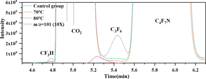
Gas chromatogram of the 10%C4F7N–90%CO2 gas mixture after aging tests.
Figure 2 shows the content of detected byproducts under different conditions. The interaction between EPDM and C4F7N–CO2 gas mixture generated 0.95 ppm (control group, 80 °C), 0.33 ppm (test group, 70 °C), and 13.01 ppm (test group, 80 °C) C3F6, respectively. It should be noted that the initial decomposition temperature of the C4F7N–CO2 gas mixture is higher than 350 or 650 °C.10,15 Therefore, there exists chemical reaction between EPDM and C4F7N at 80 °C. The peak area integral calculation shows that the content of CF3H and C2F5H increased sharply when the gas temperature reached 80 °C, indicating that the temperature has quite the effect on the reaction between the C4F7N–CO2 gas mixture and EPDM. In addition, the content of C3F6, CF3H at 70 °C is lower than the control group and the difference is relatively small. This is due to the test temperature of the control group being set to 80 °C and the detection limit of GC–MS at low content.
Figure 2.

Content of detected byproducts under different temperature conditions. (a) C3F6, (b) CF3H, and (c) C2F5H.
Overall, the gas composition analysis confirms that the chemical reaction between EPDM and C4F7N–CO2 gas mixture occurs at temperatures around 80 °C, resulting in the generation of characteristic byproducts C3F6, CF3H, and C2F5H. The duration time will also have influence on the test results because of the cumulative effect considering the long term operation of the equipment.
2.1.2. Morphology Analysis
Figure 3 shows the morphology of the EPDM rubber before and after interaction. It is apparent that the surface morphology of the untreated EPDM sample was homogeneous and smooth, and no obvious defects can be found at the magnification of 5000× and 10 000×. The appearance of white spots exists (see the red circle in Figure 3b) for the EPDM exposed to C4F7N–CO2 gas mixture at 70 °C for 90 h, indicating that C4F7N causes corrosion of EPDM. When the gas temperature reaches 80 °C, there exist white spots randomly distributed on the EPDM surface (as shown in Figure 3c). The EDPM surface is corroded seriously at this condition because strong chemical reaction occurs between them.
Figure 3.

SEM photomicrographs of EPDM rubber treated with 10%C4F7N–90%CO2 gas mixture. (a) Untreated, (b) treated at 70 °C for 90 h, and (c) treated at 80 °C for 90 h.
It should be noted that the maximum operating temperature of electrical equipment is 40 °C according to IEC 61869-1-2007. Considering the temperature-rise effect during the normal operation of GIE, the temperature of the sealing material will be in the range of 40–70 °C. Therefore, the service life of EPDM for GIE using the C4F7N gas mixture as the insulating medium reduces.
2.1.3. XPS Analysis
Table 1 shows the XPS survey analysis results. It can be found that the composition of untreated and treated EPDM at 70 °C is similar, which is quite different to the treated EPDM at 80 °C. In particular, the composition of the F element increased from 1.52% (70 °C) to 4.67% (80 °C), confirming that the fluorine accumulation process happens during the interaction. The atomic composition of N also increased by 0.97% as the temperature changes from 70 to 80 °C. The content of C and O element has a little difference for the untreated EPDM and treated EPDM at 70 °C.
Table 1. XPS Survey Analysis of the Surface of EPDM Rubber Treated with 10%C4F7N–90%CO2 Gas Mixture.
| surface
composition (at. %) |
||||
|---|---|---|---|---|
| C | F | O | N | |
| untreated | 78.51 | 1.17 | 19.54 | 0.79 |
| 70 °C | 80.55 | 1.52 | 17.13 | 0.8 |
| 80 °C | 75.61 | 4.67 | 17.95 | 1.77 |
Figure 4 gives the high-resolution XPS spectra of the EPDM rubber treated with 10%C4F7N–90%CO2 gas mixture. All the peaks were fitted based on XPS Peak software employing Gauss–Lorentz curves after subtraction of a Shirleytype background. The carbon calibrations were also conducted. As shown in Figure 4a, the characteristic peak located at 284.8 eV belongs to C–H or C–C bonds. In addition, the other two peaks are assigned to C–O, C–O–C, or C–N bond at 286.1 eV and C=O or O–C–O at 288.5 eV.25,26
Figure 4.

XPS spectra for the surface of EPDM rubber treated with 10%C4F7N–90%CO2 gas mixture. (a) C 1s, (b) O 1s, and (c) F 1s.
As for the O 1s spectra shown in Figure 4b, the peaks located at 532.3 and 533.3 eV correspond to the C=O and C–O–C component, respectively.27 Overall, the composition of C and O for the untreated and treated EPDM is similar. In addition, the high-resolution spectra of F 1s includes two characteristic peaks located at 684.5 and 688.3 eV. The binding energy of F 1s close to 684.5 eV belongs to the F that is ironically fixed to the C atom.28,29 This characteristic peak is not found for the untreated EPDM (quite low peak intensity). Moreover, the peak area of the C–F component increased obviously with temperature, indicating that the accumulation of fluorine occurs severely because of the reaction between EPDM and C4F7N–CO2. The other peak located at 688.3 eV is assigned to the CFxCHx group, corresponding to organic fluorine components. It is reported that there exists a significant shift of about 4 eV between the organic and inorganic fluoride components.30 Thus, the two peaks of F 1s confirms that the generation of the inorganic fluoride component occurs after the aging tests.
Overall, XPS results indicates that EPDM rubber undergoes accumulation of fluorine when interacted with C4F7N–CO2 gas mixture. This process is accelerated with the increase of temperature, which is consistent well with the GC–MS and SEM test results.
2.2. Interaction Mechanism between C4F7N and EPDM
2.2.1. Structure Properties and Decomposition of EPDM
In order to understand the interaction mechanism between EPDM and C4F7N, we performed DFT calculations to reveal the structure properties of the interaction system.
The typical chemical structure of EPDM consists ethylene, propylene, and diene units. Ethylidene norbornene (ENB) is usually used as diene, as shown in Figure 5.31 The ethylene–propylene–ENB chain was chosen as the EDPM polymer model for DFT calculations. This scheme is also used by Yamada et al. to investigate the interaction mechanism between nitrile rubber and fuel species based on DFT.32 Considering the complex molecular structure of C4F7N and EPDM, the interaction between them discussed in this paper is mainly concentrated on the reaction of EPDM defects or particles and C4F7N. The EPDM defects and particles have unsaturated chemical bonds, which have stronger reactivity than the EPDM molecule. That is to say, the reaction between C4F7N and EPDM defects or particles occurs easier than the EPDM molecule. In this section, we first analyzed the structural properties of the EPDM monomer. Then, the possible defect formation pathways of EPDM were analyzed. In addition, the possible interaction between the C4F7N and several kinds of EPDM defects was explored.
Figure 5.

Chemical structure of EPDM.
Figure 6 shows the calculated Mayer bond order (MBO) of EDPM. MBO is widely used to describe the relative strength of chemical bonds.33 It can be found that the C=C bond has the largest MBO value (1.763) and the MBO of the C–H bond in EDPM is smaller than most of the C–C bond. Moreover, four main dissociation paths were analyzed to reveal the formation of EDPM defects (as shown in Figure 7).
Figure 6.

MBO of EPDM.
Figure 7.

Considered decomposition paths of EPDM.
Figure 8 demonstrates the calculated reaction enthalpy of considered EPDM dissociation paths. The dissociation of EPDM through path A requires adsorption of 85.37 kcal/mol. Moreover, the bond-breaking process of EPDM through path B to generate C9H13 and C5H11 has the lowest reaction enthalpy among all the considered paths (83.76 kcal/mol), which is most likely to occur. The production of C13H21 and CH3 through Path C has the highest reaction enthalpy of 108.61 kcal/mol. The dehydrogenation process of EPDM via path D has a reaction enthalpy of 93.56 kcal/mol.
Figure 8.

Reaction enthalpy of considered decomposition paths of EPDM: at the GGA-PBE level, with ZPE correction and enthalpy correction, T = 298.15 K. (a) Dissociation path A. (b) Dissociation path B. (c) Dissociation path C. (d) Dissociation path D.
2.2.2. Reaction Mechanism between C4F7N and EPDM
The degradation of EPDM occurs during the aging process, which could generate several kinds of particles or defects on its surface. Moreover, the decomposition of C4F7N starts at temperatures higher than 350 °C.10,19 Thus, we mainly considered the reaction between C4F7N and EPDM decomposed particles or defects to investigate the reaction mechanism between them.
Table 2 gives the reaction paths and enthalpy between EPDM-decomposed particles through path A and C4F7N. All the proposed reaction paths have a negative reaction enthalpy, indicating that the reactions are thermodynamically supported. For the situation that the N atom in C4F7N close to the C11H17 and C3H7 (path A1 and A3), optimized structures show that the distance between N and C atoms is shortened. The distance of C atoms in C11H17 and N atoms in C4F7N changes to 1.473 Å after interaction. The bond angle of the CN group which connected to the central C atoms of C4F7N also changes to 140.55°. As for reaction paths A2 and A4, the F atom linked to the central C atom of C4F7N is composed of a new chemical bond with the C atom in C11H17 and C3H7, and another product C4F6N is produced after interaction. The reaction enthalpy of path A2 (−29.39 kcal/mol) and A4 (−23.44 kcal/mol) is also lower than that of A1 (−16.19 kcal/mol) and A3 (−15.84 kcal/mol), which are more likely to occur. The accumulation of fluorine might occur through these two reaction paths.
Table 2. Reaction between EPDM Decomposed Particles through Path A and C4F7N: At GGA-PBE Level, with ZPE Correction and Enthalpy Correction, T = 298.15 K.

The considered reaction paths between EPDM decomposed particles through path B and C4F7N is given in Table 3. The reaction enthalpy of all the paths is also negative. Similar to paths A1 and A3, the N atom in C4F7N tends to form new chemical bonds with EPDM defect particles. The distance between the N atom and C atom in EPDM is shortened. As for reaction paths B2 and B4, the C–F bond in C4F7N breaks and a new bond between F and C in the EPDM is produced after interaction. These two paths are more likely to occur because of the lower enthalpy, which is another possible fluorine accumulation paths.
Table 3. Reaction between EPDM Decomposed Particles through Path B and C4F7N.

Table 4 gives the interaction paths between EPDM decomposed particles through path C, D, and C4F7N. We can find that paths C2 and C1 have the lowest reaction enthalpies of −46.31 and −40.97 kcal/mol, respectively. Thus, the above two reactions are more likely to occur. In addition, the reaction mechanism for the N atom or F atom in C4F7N closed to the EPDM defect particles is similar to that of Tables 2 and Table 3.
Table 4. Reaction between EPDM Decomposed Particles through Path C, D and C4F7N.

According to the above results, the interaction between C4F7N and EPDM defects and particles will result in the adsorption and dissociation of C4F7N. The N atom in the CN group of C4F7N has the tendency to form new bonds with EPDM defects or particles. The F atom connected to the central C atom of C4F7N could react with the EPDM particles, causing the dissociation of C4F7N to generate C4F6N as well as forming a new F–C bond with EPDM. These reaction paths could explain the accumulation of fluorine on the EPDM after aging.
2.2.3. Discussion
According to the above-mentioned results, EPDM rubber is incompatible with C4F7N–CO2 gas mixture at temperatures higher than 70 °C. The interaction between them will result in the decomposition of C4F7N, generating CF3H, C3F6, and C2F5H. The corrosion of the EPDM surface occurs and the accumulation of fluorine exists.
At present, there is no general standard defined on how compatibility for materials in contact with C4F7N gas mixture has to be tested. The test procedure must be defined by the manufacturer in a way to confirm that the impact of the material on the gas and the impact of the gas and possible decomposition products on the material does not affect the safety and performance of equipment in an unacceptable level.34
In addition, Kieffel pointed out that gas permeability of the elastomer material used for gaskets should be considered because of the CO2 molecule is smaller than C4F7N or SF6. The designed O-ring for GIS should be tight with enough reliability during all its lifetime and meet the maximum allowed leakage rate of 0.5% per compartment per year as specified in IEC 62271-203.10
Butyl rubber is known to be tight toward low-molecular weight gases such as CO2 and it has been widely used in the automotive industry for tires.10 Halogenated butyl rubber which has no double bond on the main molecular chain and is not sensitive to ozone could be a candidate for C4F7N–CO2 gas mixture equipment. It was reported that the permeation rate coefficient of halogenated butyl rubber under C4F7N–a CO2 environment at 20 °C is lower than that of EPDM.10 While its stability under working temperature conditions needs to be further tested.
3. Conclusions
In this paper, we explored the compatibility between EPDM and C4F7N. The composition and morphology properties of EPDM and C4F7N–CO2 gas mixture after aging tests were obtained based on the GC–MS, SEM, and XPS. The interaction mechanism between EPDM and C4F7N is also revealed based on the DFT calculations. The following useful conclusions can be obtained,
-
(1)
EPDM exposed under a C4F7N–CO2 environment at temperatures around 80 °C will result in the decomposition of C4F7N, producing several characteristic byproducts including C3F6, CF3H, and C2F5H. The EDPM surface will be corroded seriously at temperatures around 80 °C. The fluorine accumulation process also exists during the interaction.
-
(2)
Interaction between C4F7N and EPDM defects and particles cause the adsorption and dissociation of C4F7N. The N atom in the CN group of C4F7N has the tendency to form new bonds with the EPDM. In addition, the F atom connected to the central C atom of C4F7N could react with EPDM particles to generate C4F6N as well as form new F–C bonds with EPDM.
-
(3)
EPDM rubber is incompatible with the C4F7N–CO2 gas mixture at temperatures higher than 70 °C. It is necessary to conduct relevant modification on EPDM or finding other compatible rubber used as the O-ring for C4F7N–CO2 GIE in engineering application.
4. Methods
4.1. Experimental Methods
4.1.1. Test Platform
The aging tests were conducted to explore the compatibility between EPDM and C4F7N. The test platform mainly consists of the heating system, the temperature control system and the gas chamber (as shown in Figure 9). The gas chamber with a volume 2 L is made of 304 L stainless-steel, which could withstand a high pressure of 0.6 MPa. The stainless-steel sample holder is placed at the bottom of the gas chamber to carry the EDPM rubber sample. The gas chamber is sealed using the fluororubber, which generally has wide chemical resistance. All the test chambers were sealed tightly, and no gas leakage was found during the test. The heating element is put in the center of the heat transfer bushing, which is installed on the top cover plate of the gas chamber. The temperature control system consists of the temperature sensor, the switch power supply and the solid-state relay. The K-type temperature sensor is used to monitor the temperature of the C4F7N–CO2 gas mixture. The gas sensor sends signals to the proportion integration differentiation controller. The controller could compare the actual temperature with the set value and send a control signal to the solid-state relay to realize the switching power supply control.
Figure 9.

Structure of the aging test system.
4.1.2. Materials and Test Conditions
We used the C4F7N–CO2 gas mixture to carry out thermal aging tests. Relevant studies reported that CO2 has a great synergism effect with C4F7N, and CO2 also shows better arc quenching capabilities compared with N2.8 It was pointed out that the concentration of C4F7N in the gas mixture should be less than 10% for the working pressure of 0.5 MPa. Thus, we used 10%C4F7N–90%CO2 gas mixture to conduct relevant tests. C4F7N is supplied by 3 M China with a purity higher than 99.2%. In addition, the standard gas for 10%C4F7N–90%CO2 is provided by Wuhan Newradar Special Gas Co., Ltd. The EPDM rubber O-rings is supplied by Xu Ji Group Corporation, State Grid.
The EPDM O-ring we obtained is cylindrical as shown in Figure 10. The sealing ring was cut into the semi-cylindrical structure for the convenience of relevant SEM and XPS testing. The semi-cylindrical O-ring was put on the sample holder in the chamber. The gas chamber was evacuated using the vacuum pump to 10–4 to 10–5 Pa first and then filled with 10%C4F7N–90%CO2 to 0.3 MPa. This procedure is repeated 3 times to remove gas impurities. As for the control group, EPDM was not put in the test chamber. The gas pressure of all the test groups is set to 0.3 MPa. The using of 0.3 MPa is for the safety consideration because the heating of the gas mixture will result in the gas pressure increase. In addition, it was reported that the current-carrying metallic conductor of GIE for engineering application has a temperature rise effect of about 70 °C (the absolute temperature lower than 115 °C) normally.15 While the temperature of the equipment shell and O-rings is usually around 40–70 °C (absolute temperature). Thus, the test temperature condition in this paper was set to 70 and 80 °C. The duration time also has influence on the test results because of the cumulative effect. Here, the exposure time is set to 90 h to explore the interaction between EPDM and C4F7N–CO2 gas mixture. There are currently no compatibility testing standards for the non-SF6 gas insulating medium with materials. The select of 90 h is based on the time cost.
Figure 10.

Structure of the EPDM semi cylindrical O-ring.
4.1.3. Morphology and Component Analysis
The gas mixture after aging tests were collected and analyzed using GC–MS (Shimadzu QP2010 Ultra). The column type is CP-Sil5CB (60 m × 8 μm × 0.32 mm). Both the SCAN and SIM method were used to detect the gas components. The heating scheme of the GC is listed as follows: (1) Keep the column at 32 °C for 10 min. (2) Heat the column to150 °C at the rate of 60 °C/min and retain it for 2 min. The gas component is confirmed based on the NIST (National Institute of Standards and Technology) standard database and standard gases.
The morphology of the EPDM was analyzed using a Zeiss SIGMA field-emission scanning electron microscope manufactured by Carl Zeiss. Moreover, the components of the EPDM surface were detected by XPS (ESCALAB250Xi electron spectrometer manufactured by Thermo Fisher Scientific of United States).
4.2. Theoretical Methods
In order to investigate the interaction mechanism between C4F7N and EPDM, we carried out spin-polarized DFT calculations based on the Dmol3 package of Materials Studio.35,36 DFT has been widely used to calculate the structure and ground-state energy of molecules.6,7 The generalized gradient approximation with the Perdew–Burke–Ernzerhof functional [generalized gradient approximation (GGA)-PBE] method was applied to treat the electron exchange and correlation.37 We chose the double numerical plus polarization (DNP) as the atomic basis set and all electron core treatment was selected.38 The convergence tolerance for geometry optimization calculation was listed as follows: (1) 1.0 × 10⁻⁶ Ha for energy, (2) 0.005 Å for displacement, and (3) 0.002 Ha/Å for gradients. Frequency analysis was also conducted for all the reactants and products.
The reaction enthalpy is defined as follows
| 1 |
The negative value of reaction enthalpy indicates that the reaction is thermodynamic spontaneous and the positive value of the reaction enthalpy means the reaction belongs to endothermic process. Zero-point vibration energy and enthalpy correction (at 298.15 K) were both considered for reaction enthalpy calculations. It should be noted that the numerical basis sets implemented in Dmol3 code are more complete than the traditional Gaussian functions, thereby minimizing or even eliminating basis set superposition error.39−42
Acknowledgments
The current work is supported by the National Natural Science Foundation of China (nos. 51707137, 51877157). The author also thanks to the support from China Scholarship Council (grant no. 201906270122).
The authors declare no competing financial interest.
References
- Fu Y.; Rong M.; Wang X.; Yang A. Rate constants of C5F10O decomposition reactions at temperatures of 300-3500 K. J. Phys. D: Appl. Phys. 2019, 52, 035202. 10.1088/1361-6463/aae8d5. [DOI] [Google Scholar]
- Zhang Y.; Zhang X.; Li Y.; Li Y.; Chen Q.; Zhang G.; Xiao S.; Tang J. AC breakdown and decomposition characteristics of environmental friendly gas C5F10O/air and C5F10O/N2. IEEE Access 2019, 7, 73954–73960. 10.1109/access.2019.2915372. [DOI] [Google Scholar]
- Li Y.; Zhang Y.; Li Y.; Tang F.; Lv Q.; Zhang J.; Xiao S.; Tang J.; Zhang X. Experimental study on compatibility of eco-friendly insulating medium C5F10O/CO2 gas mixture with copper and aluminum. IEEE Access 2019, 7, 83994–84002. 10.1109/access.2019.2923015. [DOI] [Google Scholar]
- Chen D.; Zhang X.; Xiong H.; Li Y.; Tang J.; Xiao S.; Zhang D. A First-principles study of the SF6 decomposed products adsorbed over defective WS2 monolayer as promising gas sensing device. IEEE Trans. Device Mater. Reliab. 2019, 19, 473–483. 10.1109/tdmr.2019.2919773. [DOI] [Google Scholar]
- Beroual A.; Haddad A. Recent advances in the quest for a new insulation gas with a low impact on the environment to replace sulfur hexafluoride (SF6) gas in high-voltage power network applications. Energies 2017, 10, 1216. 10.3390/en10081216. [DOI] [Google Scholar]
- Cui H.; Liu T.; Zhang Y.; Zhang X. Ru-InN Monolayer as a gas scavenger to guard the operation status of SF6 insulation devices: a first-principles theory. IEEE Sens. J. 2019, 19, 5249–5255. 10.1109/jsen.2019.2899966. [DOI] [Google Scholar]
- Cui H.; Zhang X.; Li Y.; Chen D.; Zhang Y. First-principles insight into Ni-doped InN monolayer as a noxious gases scavenger. Appl. Surf. Sci. 2019, 494, 859–866. 10.1016/j.apsusc.2019.07.218. [DOI] [Google Scholar]
- Rabie M.; Franck C. M. Assessment of eco-friendly gases for electrical insulation to replace the most potent industrial greenhouse gas SF6. Environ. Sci. Technol. 2018, 52, 369–380. 10.1021/acs.est.7b03465. [DOI] [PubMed] [Google Scholar]
- Kieffel Y.; Irwin T.; Ponchon P.; Owens J. Green gas to replace SF6 in electrical grids. IEEE Power Energy Mag. 2016, 14, 32–39. 10.1109/mpe.2016.2542645. [DOI] [Google Scholar]
- Kieffel Y. Characteristics of g3-an alternative to SF6. Proc. IEEE Int. Conf. Dielectr. 2016, 2, 880–884. 10.1109/ICD.2016.7547757. [DOI] [Google Scholar]
- Nechmi H. E.; Beroual A.; Girodet A.; Vinson P. Effective ionization coefficients and limiting field strength of fluoronitriles-CO2 mixtures. IEEE Trans. Dielectr. Electr. Insul. 2017, 24, 886–892. 10.1109/tdei.2017.006538. [DOI] [Google Scholar]
- Zhao H.; Li X.; Tang N.; Jiang X.; Guo Z.; Lin H. Dielectric properties of fluoronitriles/CO2 and SF6/N2 mixtures as a possible SF6-substitute gas. IEEE Trans. Dielectr. Electr. Insul. 2018, 25, 1332–1339. 10.1109/tdei.2018.007139. [DOI] [Google Scholar]
- Li Y.; Zhang X.; Zhang J.; Fu M.; Zhuo R.; Luo Y.; Chen D.; Xiao S. Experimental study on the partial discharge and AC breakdown properties of C4F7N/CO2 mixture. High. Volt. 2019, 4, 12–17. 10.1049/hve.2018.5049. [DOI] [Google Scholar]
- Chachereau A.; Hösl A.; Franck C. M. Electrical insulation properties of the perfluoronitrile C4F7N. J. Phys. D: Appl. Phys. 2018, 51, 495201. 10.1088/1361-6463/aae458. [DOI] [Google Scholar]
- Li Y.; Zhang X.; Chen Q.; Zhang J.; Chen D.; Cui Z.; Xiao S.; Tang J. Study on the thermal interaction mechanism between C4F7N-N2 and copper, aluminum. Corros. Sci. 2019, 153, 32–46. 10.1016/j.corsci.2019.03.031. [DOI] [Google Scholar]
- Yu X.; Hou H.; Wang B. Mechanistic and kinetic investigations on the thermal unimolecular reaction of heptafluoroisobutyronitrile. J. Phys. Chem. A 2018, 122, 7704–7715. 10.1021/acs.jpca.8b07189. [DOI] [PubMed] [Google Scholar]
- Zhong L.; Wang J.; Xu J.; Wang X.; Rong M. Effects of buffer gases on plasma properties and arc decaying characteristics of C4F7N–N2 and C4F7N–CO2 arc plasmas. Plasma Chem. Plasma Process. 2019, 39, 1379–1396. 10.1007/s11090-019-10015-8. [DOI] [Google Scholar]
- Li Y.; Zhang X.; Xiao S.; Chen Q.; Tang J.; Chen D.; Wang D. Decomposition properties of C4F7N/N2 gas mixture: an environmentally friendly gas to replace SF6. Ind. Eng. Chem. Res. 2018, 57, 5173–5182. 10.1021/acs.iecr.8b00010. [DOI] [Google Scholar]
- Zhang B.; Li C.; Xiong J.; Zhang Z.; Li X.; Deng Y. Decomposition characteristics of C4F7N/CO2 mixture under AC discharge breakdown. AIP Adv. 2019, 9, 115212. 10.1063/1.5115588. [DOI] [Google Scholar]
- Fu Y.; Wang X.; Wang X.; Yang A.; Rong M.; Duan J. Theoretical study on decomposition pathways and reaction rate constants of C4F7N with O atom. J. Phys. D: Appl. Phys. 2019, 53, 105202. 10.1088/1361-6463/ab5739. [DOI] [Google Scholar]
- Wu Y.; Wang C.; Sun H.; Murphy A. B.; Rong M.; Yang F.; Chen Z.; Niu C.; Wang X. Properties of C4F7N–CO2 thermal plasmas: thermodynamic properties, transport coefficients and emission coefficients. J. Phys. D: Appl. Phys. 2018, 51, 155206. 10.1088/1361-6463/aab421. [DOI] [Google Scholar]
- Preve C.; Lahaye G.; Richaud M.; Maladen R.; Penelon T.; Galas S. Hazard study of medium-voltage switchgear with SF6 alternative gas in electrical room. CIRED—Open Access Proc. J. 2017, 2017, 198–201. 10.1049/oap-cired.2017.0385. [DOI] [Google Scholar]
- Li Y.; Zhang X.; Zhang J.; Xiao S.; Xie B.; Chen D.; Gao Y.; Tang J. Assessment on the toxicity and application risk of C4F7N: A new SF6 alternative gas. J. Hazard. Mater. 2019, 368, 653–660. 10.1016/j.jhazmat.2019.01.100. [DOI] [PubMed] [Google Scholar]
- Huang R.; Zhang X.; Zeng Q.; Tao W.; Zhu Z.; Meng Y.; Wang X.; Lin S.. Study on aging of material for GIS sealing ring. TENCON 2015–2015 IEEE Region 10 Conference; IEEE, 2015; pp 1–4.
- Liu J.; Li X.; Xu L.; Zhang P. Investigation of aging behavior and mechanism of nitrile-butadiene rubber (NBR) in the accelerated thermal aging environment. Polym. Test. 2016, 54, 59–66. 10.1016/j.polymertesting.2016.06.010. [DOI] [Google Scholar]
- Da Maia J. V.; Pereira F. P.; Dutra J. C. N.; Mello S. A. C.; Becerra E. A. O.; Massi M.; Sobrinho A. S. D. S. Influence of gas and treatment time on the surface modification of EPDM rubber treated at afterglow microwave plasmas. Appl. Surf. Sci. 2013, 285, 918–926. 10.1016/j.apsusc.2013.09.013. [DOI] [Google Scholar]
- Zhou Y.; Wang W.; Dou R.; Li L.-p.; Yin B.; Yang M.-b. Effect of EPDM-g-MAH on the morphology and properties of PA6/EPDM/HDPE ternary blends. Polym. Eng. Sci. 2013, 53, 1845–1855. 10.1002/pen.23445. [DOI] [Google Scholar]
- Nansé G.; Papirer E.; Fioux P.; Moguet F.; Tressaud A. Fluorination of carbon blacks. An X-ray photoelectron spectroscopy study. Part II. XPS study of a furnace carbon black treated with gaseous fluorine at temperatures below 100° C. Influence of the reaction parameters and of the activation of the carbon black on the fluorine fixation. Carbon 1997, 35, 371–388. 10.1016/s0008-6223(97)89609-1. [DOI] [Google Scholar]
- He W.; Zhou Y.; Chen X.; Guo J.; Zhou D.; Chen S.; Wang M.; Li L. Novel intumescent flame retardant masterbatch prepared through different processes and its application in EPDM/PP thermoplastic elastomer: Thermal stability, flame retardancy, and mechanical properties. Polymers 2019, 11, 50. 10.3390/polym11010050. [DOI] [PMC free article] [PubMed] [Google Scholar]
- Gabler C.; Dörr N.; Allmaier G. Influence of cationic moieties on the tribolayer constitution shown for bis (trifluoromethylsulfonyl) imide based ionic liquids studied by X-ray photoelectron spectroscopy. Tribol. Int. 2014, 80, 90–97. 10.1016/j.triboint.2014.06.018. [DOI] [Google Scholar]
- Wang W.; Tanaka Y.; Takada T.; Iwata S.; Uehara H.; Li S. Influence of oxidation on the dynamics in amorphous ethylene-propylene-diene-monomer copolymer: A molecular dynamics simulation. Polym. Degrad. Stab. 2018, 147, 187–196. 10.1016/j.polymdegradstab.2017.12.001. [DOI] [Google Scholar]
- Yamada T.; Graham J. L.; Minus D. K. Density functional theory investigation of the interaction between nitrile rubber and fuel species. Energy Fuels 2008, 23, 443–450. 10.1021/ef8006189. [DOI] [Google Scholar]
- Bridgeman A. J.; Cavigliasso G.; Ireland L. R.; Rothery J. The Mayer bond order as a tool in inorganic chemistry. J. Chem. Soc., Dalton Trans. 2001, 2095–2108. 10.1039/b102094n. [DOI] [Google Scholar]
- Kessler F.; Sarfert-Gast W.; Ise M.; Goll F.. Interaction of low global warming potential gaseous dielectrics with materials of gas-insulated systems. Proceedings 20th International Symposium High Voltage Engineering, 2017.
- Delley B. From molecules to solids with the DMol3 approach. J. Chem. Phys. 2000, 113, 7756–7764. 10.1063/1.1316015. [DOI] [Google Scholar]
- Li Y.; Zhang X.; Chen D.; Li Y.; Zhang J.; Cui Z.; Xiao S.; Tang J. Theoretical study on the interaction between C5-PFK and Al (1 1 1), Ag (1 1 1): A comparative study. Appl. Surf. Sci. 2019, 464, 586–596. 10.1016/j.apsusc.2018.09.112. [DOI] [Google Scholar]
- Perdew J. P.; Burke K.; Ernzerhof M. Generalized gradient approximation made simple. Phys. Rev. Lett. 1996, 77, 3865. 10.1103/physrevlett.77.3865. [DOI] [PubMed] [Google Scholar]
- Delley B. An all-electron numerical method for solving the local density functional for polyatomic molecule. J. Chem. Phys. 1990, 92, 508–517. 10.1063/1.458452. [DOI] [Google Scholar]
- Inada Y.; Orita H. Efficiency of numerical basis sets for predicting the binding energies of hydrogen bonded complexes: evidence of small basis set superposition error compared to Gaussian basis sets. J. Comput. Chem. 2008, 29, 225–232. 10.1002/jcc.20782. [DOI] [PubMed] [Google Scholar]
- Qiu C. S.; Flinn C.; Zhao Y. Molecular structure and electronic properties of substituted tetrabenzocoronenes: DFT and TD-DFT investigations. J. Phys. Org. Chem. 2019, 32, e3970 10.1002/poc.3970. [DOI] [Google Scholar]
- Li Y.; Zhang X.; Zhang J.; Xie C.; Shao X.; Wang Z.; Chen D.; Xiao S. Study on the thermal decomposition characteristics of C4F7N–CO2 mixture as ecofriendly gas-insulating medium. High. Volt. 2020, 5, 46. 10.1049/hve.2019.0032. [DOI] [Google Scholar]
- Li Y.; Zhang X.; Ye F.; Chen D.; Tian S.; Cui Z. Influence regularity of O2 on dielectric and decomposition properties of C4F7N-CO2-O2 gas mixture for MV equipment. High. Volt. 2020, 10.1049/hve.2019.0219. [DOI] [Google Scholar]