

Abstract
The use of nanomaterials has transformed fields such as medicine and electronics. However, aggregation of nanomaterials in aqueous solutions, difficult recovery of spent nano-adsorbents from reactors, and a tremendous pressure loss caused by nano-adsorbents in adsorption columns have prevented the wide-scale use of nano-adsorbents in industrial applications for water purification. An over-reliance on traditional adsorption media for fluid purification practices has slowed innovation in this field. This study serves as a proof of concept for a new approach in utilizing nano-adsorbents in water treatment. A system based on the concept of renal dialysis was used to treat a solution of arsenite using two-line ferrihydrite (Fh) under environmental conditions. The performance was compared to traditional batch studies, and environmental variables pH and Eh were monitored. The system removed 67 and 91% of arsenite at 1.22 and 2.61 g/L Fh loadings, respectively, in comparison to batch experiments that removed 82 and 94% for similar loadings. Operational conditions and the physical design of the vessel limited the extent of removal that could be obtained with the system. Design advantages, shortcomings, and required improvements are discussed.
Introduction
Adsorption has emerged as a cost-effective method for fluid purification, including water treatment. Unfortunately, large-scale adsorption technologies have failed to evolve as quickly as new materials have been discovered. In the water treatment industry, much of the industry still heavily relies on activated carbon, microsized metal oxides, and ion exchange resins. Nanomaterials are not suitable for conventional fixed bed or flow-through systems. They create large pressure drops, have poor mechanical strength, and, more importantly, are difficult to separate from water.1 Although some researchers have attempted to fix nano-adsorbents onto supporting media that can be adapted to current treatment systems, this process inherently limits the utility of the material.2 Much work with nano-adsorption has remained at the laboratory stage, and translation to industrial-scale use considerably lags in comparison to other fields such as electronics and medicine.3
The concept of a hemodialyzer, which is used in medicine as a biomimetic for artificial kidneys, suggests an alternative method for the application of nanomaterials in water treatment. During hemodialysis, blood is pumped into the hemodialyzer through an inlet and is distributed into a membrane. Pressure and a concentration gradient induce mass transfer through the membrane, and waste products and excess fluid are removed as blood flows to the outlet. Simultaneously, a dialysate solution is pumped in a counterflow direction outside the membrane and carries away the waste.4,5 This same process can be adapted for the use of nanomaterials in water treatment and fluid purification in general. As a contaminated stream is passed on one side of a selective membrane, a counterflowing service fluid of nano-adsorbents is passed on the other side. As contaminants pass through the membrane, they can be picked up by fast-acting nano-adsorbents. This concept can also be applied more simply by passing a service fluid with unidirectional flow over a membrane containing a stagnant contaminant solution.
In the following proof-of-concept experiments, we demonstrate a simplified application of the hemodialyzer (renal dialysis) concept for fluid purification. A dialysis system is utilized to adsorb arsenite (as H3AsO3 at or near a circumneutral pH) with two-line ferrihydrite (Fh). The system’s removal efficiency is assessed and compared to traditional batch experiments. Changes in environmental process variables Eh and pH are monitored and reported throughout the treatment period. The Results and Discussion section considers benefits and limitations of the system and notes areas of needed improvement. To the best of our knowledge, this is the first-ever reported application of nanomaterials in dialysis-based treatment. Motivation for the use of arsenic and Fh as a model contaminant and nano-adsorbent, respectively, follows.
Arsenic is a naturally occurring metalloid that is both abundant and ubiquitous in the Earth’s crust and is released in large quantities through industrial processes and agricultural applications.6,7 Exposure to arsenic occurs through contaminated food, water, and air, and the risk of exposure and potential adverse health effects have been well documented.7−10 In the environment, arsenic combines with other elements and is found in several organic and inorganic forms,11 but arsenite is the most mobile and toxic.12,13 Adsorption of arsenic onto iron oxide minerals has been investigated over the years,14−17 and Fh, a naturally occurring nanomaterial and precursor to more crystalline iron oxides,18,19 has gained substantial interest. Fh is an intrinsically nanodimensional material (2–3 nm diameter) with a Brunauer–Emmett–Teller (BET) surface area between 133 and 320 m2/g, a high adsorption capacity,20−24 and strong binding to arsenic via inner-sphere 2C and 2E complexes,24,25 which make it a desirable nano-adsorbent.
Results and Discussion
Characterization of Fh
Fh used in the experiments was prepared using a solvent deficient method (SDM). The X-ray diffraction (XRD) diffractogram in Figure 1 identifies the material as two-line Fh. The two broad peaks at 35 and 62.5° that define two-line Fh are in good agreement with Bragg peaks reported in the literature ranging from 34 to 35° and 61 to 63° 2θ, respectively, for Cu Kα (λ = 1.54060) irradiation.19,22,26−31 The Fourier transform infrared (FTIR) spectrum in Figure 2 shows broad bands at 3400 and 3200 cm–1 attributable to structural hydroxide and sorbed H2O, respectively. A series of peaks between 1750 and 800 cm–1 are associated with the various vibrational modes of bicarbonate and carbonate, which are formed from adsorbed CO2.32−35 As indicated by the white circle-bounded particles in the transmission electron microscopy (TEM) image of Figure 3A, the material is composed of individual particles with diameters less than 10 nm in size. Furthermore, the scanning electron microscopy (SEM) image in Figure 3B shows that the material is aggregated with smaller particles of varying size and shape embedded into larger particles. BET measurements show that Fh has a high surface area of 192 m2/g, falling within the lower end of values found in the literature and lower than the 250 m2/g reported by Smith et al.26 However, different batches produced using the SDM yielded surface areas varying from 192 to 329 m2/g (Table S1), and special attention should be paid to the reported surface area values (Table S2). The observed correlation between the adsorbent age and measured surface area is discussed in the Supporting Information.
Figure 1.

Powder XRD diffractogram (Cu Kα λ = 1.54060) of Fh synthesized by the SDM.
Figure 2.

ATR–FTIR spectrum of Fh synthesized by the SDM.
Figure 3.

TEM (A) and SEM (B) images of Fh after synthesis by the SDM. Single particles of Fh are bounded by white circles within the TEM image for size comparison.
Dialysis System Performance
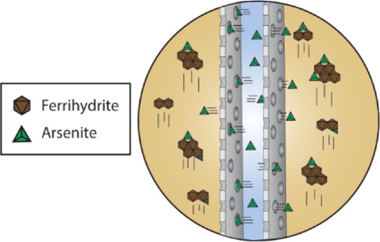
The mechanism of arsenite removal using the dialysis system is illustrated in Figure 4. A service fluid composed of Fh particles suspended in water by mixing was pumped continuously through the bottom inlet of a tube containing a membrane. Arsenite that was manually added into the lumen of the membrane diffused into the service solution over time and most adsorbed onto Fh particles flowing through the tube.
Figure 4.

Proposed dialysis system for the application of nanomaterials in fluid purification. Arsenite solution added to the lumen of the membrane diffuses into the service solution and is adsorbed by Fh particles that are continuously flowing up through the dialysis tube.
Figure 5A,B shows the dialysis system’s removal of arsenite using 1.22 and 2.61 g/L Fh loadings. The amounts of arsenite in the lumen and in the service fluid over time are presented as mass fractions of the total arsenite added to the lumen initially. Total arsenite for the 1.22 and 2.61 g/L loadings was 20.2 and 25.1 mg, respectively. During treatment, the amount of arsenite in the lumen decreased by 95% (1.22 g/L Fh) and 98% (2.61 g/L Fh), and the amount of arsenite in the service fluid slowly increased as arsenite was both distributed into the service fluid and adsorbed by Fh. By the end of 3 h, adsorption was complete as the concentration in the service fluid had plateaued. However, the 2.61 g/L Fh loading had a lower residual mass of arsenite in the service fluid, indicating that a greater portion of arsenite was adsorbed.
Figure 5.

Residual arsenite in the membrane lumen and service fluid of the system over time for 1.22 (A) and 2.61 g/L (B) adsorbent loadings. The amount of arsenite is presented as a mass fraction of total arsenic.
Adsorbed arsenite was calculated using a mass balance on total arsenite according to eq 1.
| 1 |
In eq 1, CiLSVi is the initial mass of arsenite in the lumen solution (total arsenic); CfLSVf is the mass of arsenite in the lumen solution at the end
of the experiment;  is the mass of arsenite sampled from the
service fluid during the runtime; CmSFVf is the
residual mass of arsenite in the service fluid at the end of the experiment;
and m is the total number of samples taken from the
service fluid. Thus, removal efficiency for each loading (REsys) was quantified by the mass fraction of the adsorbed arsenite and
was calculated at 67 and 91% for 1.22 and 2.61 g/L adsorbent loadings,
respectively. The 1.22 g/L loading with 20.2 mg of total arsenite
had a lower removal efficiency than the 2.61 g/L adsorbent loading
with 25.8 mg of total arsenite, suggesting that a smaller total arsenic
to Fh ratio results in better removal.
is the mass of arsenite sampled from the
service fluid during the runtime; CmSFVf is the
residual mass of arsenite in the service fluid at the end of the experiment;
and m is the total number of samples taken from the
service fluid. Thus, removal efficiency for each loading (REsys) was quantified by the mass fraction of the adsorbed arsenite and
was calculated at 67 and 91% for 1.22 and 2.61 g/L adsorbent loadings,
respectively. The 1.22 g/L loading with 20.2 mg of total arsenite
had a lower removal efficiency than the 2.61 g/L adsorbent loading
with 25.8 mg of total arsenite, suggesting that a smaller total arsenic
to Fh ratio results in better removal.
Changes in pH of the system over the course of the treatment process are shown in Figure 6A. The introduction of Fh into the service solution caused a sudden drop in pH for both loadings. Fh has been reported to accumulate protons when exposed to air through a series of reactions as carbon dioxide adsorbs onto its bound water layer.32−34 This likely occurred during the final drying stage of the synthetic process and is indicated by the FTIR spectrum in Figure 3. The increased surface acidity transferred into the service fluid during the addition of Fh and likely caused a pH drop proportional to the loading. As treatment progressed, adsorption of arsenite onto Fh caused the increase in pH for both loadings. It has been reported that arsenite adsorbs onto Fh through several possible adsorption reactions, resulting in either the net release of H+ or OH– depending on the operating pH.36 The 2.61 g/L loading had a smaller pH recovery than the 1.22 g/L loading because of the higher initial acidity produced by excess Fh.
Figure 6.

Changes in pH (A) and Eh (B) of the service fluid with 1.25 and 2.68 g/L Fh loadings.
Figure 6B shows the variance in Eh measurements of the system for both loadings. The redox potential is influenced by changes in pH according to the Nernst equation, and the two parameters have an inverse relationship. The steep drop in pH followed by the introduction of Fh was mirrored by a corresponding spike in Eh, and the subsequent pH recovery throughout the remaining runtime was mirrored by a decrease in Eh. For each loading, the extent of change in Eh was also proportional to the change in pH, with the 2.61 g/L loading having a larger drop in pH and a larger spike in Eh in comparison to the 1.21 g/L loading.
Batch Adsorption
For batch adsorption experiments,
Fh was added to beakers containing arsenite solution and stirred while
samples were taken over time. Figure 7A,B shows the removal of arsenite with 1.25 and 2.68
g/L loadings. The amount of arsenite remaining in the solution at
each point in time is presented as a mass fraction of the total arsenite
introduced initially. The amount of arsenite adsorbed onto Fh is calculated
using a mass balance on the total arsenite according to eq 2 as follows: CiVi is the initial mass of arsenite
in solution;  is the accumulated mass
removed from sampling; CmVf is the final mass remaining in solution;
and m is
the total number of samples.
is the accumulated mass
removed from sampling; CmVf is the final mass remaining in solution;
and m is
the total number of samples.
| 2 |
Figure 7.

Removal of arsenite in batch experiments over time for 1.25 (A) and 2.68 g/L (B) adsorbent loadings. The amount of arsenite remaining in solution is presented as a mass fraction of total arsenic.
In the experimental replicates, most of the arsenite was removed within 30 min. Additional reaction time minimally increased the overall removal. For the 1.25 g/L loading, Table 1 shows that on average, 73% of the total arsenite in solution was removed within 30 min and 82% within 3 h. Thus, 89% of the arsenite was removed within that 30 min mark, leaving 11% to be adsorbed in 2.5 h. For the 2.68 g/L loading, Table 2 shows that on average, 94% of the total arsenite and all arsenite that would be removed was removed within 30 min. Raven et al., 1998 (ref (20)), also showed similar adsorption behavior, having high initial removal in less than 30 min in 2 g/L Fh suspensions containing 40.01 and 2000.4 mg/L arsenite at pH 9.2. Li et al., 2011 (ref (22)), also reported 90% adsorption within 1 h using a 0.25 g/L Fh loading in a 5 mg/L arsenite solution at pH 7. Zhu et al., 2011 (ref (23)), attributed this behavior to a biphasic sorption process. Working with a 5 g/L Fh loading in a 525 mg/L arsenite solution at pH 6, it was noted that a fast, initial sorption process occurred within 0.167 h (10 min), followed by a slower secondary sorption process. Overall, these prior reports indicate that the adsorption process of arsenite to Fh is fast (Table S3). Rapid adsorption can have a profound effect on treatment processes, minimizing both the required contact time (hydraulic retention time) and the size of treatment systems (footprint).
Table 1. Accumulated Removal of As Over Time for 1.25 g/L Fh Loading.
| fraction
As removed |
statistics |
|||||
|---|---|---|---|---|---|---|
| Δt (min) | C | E1 | E2 | E3 | E avg | E SD |
| 30 | –0.061 | 0.727 | 0.756 | 0.699 | 0.727 | 0.029 |
| 90 | –0.101 | 0.784 | 0.816 | 0.814 | 0.804 | 0.018 |
| 180 | –0.050 | 0.804 | 0.814 | 0.841 | 0.820 | 0.019 |
Table 2. Accumulated Removal of As Over Time for 2.68 g/L Fh Loading.
| fraction
As removed |
statistics |
|||||
|---|---|---|---|---|---|---|
| Δt (min) | C | E1 | E2 | E3 | E avg | E SD |
| 30 | –0.013 | 0.938 | 0.943 | 0.936 | 0.939 | 0.004 |
| 90 | 0.036 | 0.923 | 0.925 | 0.918 | 0.922 | 0.004 |
| 180 | –0.068 | 0.941 | 0.939 | 0.934 | 0.938 | 0.004 |
Variation of pH and Eh over time for the two Fh loadings is shown in Figure 8A,B. As observed in the system, there is large drop in pH and a large increase in Eh. The changes in pH and Eh were inversely related and in proportion to the loading of Fh. Unlike the dialysis system, the overall change for both parameters was smoother and occurred over a longer period without a recovery. This is likely a combined effect from the introduction of Fh protons into water and from arsenite adsorption onto Fh. This contention is further supported by other experiments from our laboratory (Figure S1) where 1.25 g/L Fh was added to a solution imitating the ionic strength and pH of the batch reactions without arsenite. In this circumstance, the pH dropped sharply and plateaued within 5 min.
Figure 8.

Changes in pH (A) and Eh (B) of batch arsenic removal with 1.25 and 2.68 g/L Fh loadings.
Comparison of Arsenite Removal by Dialysis to Batch Adsorption
Performance of the dialysis-based system in comparison to batch adsorption was dependent on the Fh loading and the behavior of the material over the treatment process. In both the dialysis system and batch adsorption, higher Fh loadings resulted in greater removal efficiencies, but batch adsorption was overall more efficient than the system. At the lower 1.22 g/L adsorbent loading, the dialysis system had less total arsenite in contrast to its batch counterpart, yet it removed only 67% of the total arsenite in comparison to the 82% average removed by batch adsorption. At the higher 2.61 g/L adsorbent loading, where the total arsenite was similar in the dialysis system and in the batch replicates, the system removed 91% of the total arsenite in comparison to the average 94% removed by batch adsorption. Most of the arsenite passed from the membrane lumen into the service fluid within the treatment period according to Figure 5, and given that batch experiments showed adsorption to be fast, differences in performance cannot be attributed to the unavailability of arsenite for adsorption or an insufficient treatment time. Differences are attributed to changes in dispersion of Fh over time within the treatment mixtures. Figure 9A shows that Fh in both batch and dialysis system processes is introduced as a distribution of particles generally well below 100 μm in cross section. These particles disperse in solution into a fine colloidal suspension that should facilitate the fast adsorption of arsenite. However, the adsorbent in the dialysis system undergoes noticeable physical changes over the course of the treatment process. As seen in Figure 9B, particles aggregate to a large size and can lodge in rough surfaces within the body of the system. Dispersion of the adsorbent is reduced and is easily noticed by an increase in translucency of the service fluid. This phenomenon likely adversely affected the removal efficiency of the 1.22 g/L system loading. The 2.61 g/L system loading was able to maintain a high removal because of the excess Fh present that can counteract the effect of particle aggregation. The addition of excess adsorbent, however, underutilizes the material’s adsorption capacity. The adsorption capacity of Fh can be calculated as a weight percent by taking the ratio between the concentration of arsenic adsorbed and the adsorbent loading. For the 1.22 and 2.61 g/L system loadings, the adsorption capacity is 3.9 and 3.0% w/w, respectively, in comparison to 6.5 and 3.2% w/w for batch adsorption. The adsorption capacity for Fh in the literature has been reported between 2 and 20% (adapted as w/w) and is heavily dependent on experimental conditions (Table S3).
Figure 9.

SEM of Fh particles before (A) and after (B) use in the dialysis system for arsenite removal.
Dialytic System Implications and Design Improvements
The dialysis system has demonstrated successful removal of arsenite using nano-adsorbents. However, several modifications are needed to improve the performance and overall reliability for industrial applications. As previously mentioned, nanoparticles aggregate over time to sizes several orders of magnitude higher than the original particle sizes (Figure 8). The physical structure of the system and formation of eddies entrap the adsorbent particles into crevices and uneven surfaces and immobilize a fraction of the adsorbent. Entrapment could be mitigated in part with improved fluidic design but aggregation must also be addressed. One contributing factor to aggregation may be the increased collision frequency between nanoparticles due to flow shear forces. Flume experiments with CeO2 nanoparticles have demonstrated that shear forces during flow increase z-average particle size over time as analyzed by dynamic light scattering (DLS).37 Nanomaterials also have a natural tendency to aggregate because of the instability of their surface charges, and the high ionic strength service fluid may enhance this effect.38,39 Liu et al., 2019 (ref (41)), investigated the aggregation of the more crystalline six-line Fh (diameter ∼6 nm) using DLS and showed that the hydrodynamic radius increases more dramatically over time in higher ionic strength conditions near neutral pH. High salt solutions transmit ion charges, reduce electrostatic repulsion, and lower the energy barrier needed for collisions to form aggregates.40 This suggests that reducing the ionic strength may serve to minimize aggregation, but may impose limitations on the operating parameters under real-world conditions. Some studies suggest that the incorporation of chemical additives with strongly coordinating ligands, such as organic acids, into adsorbent mixtures can suppress aggregation.41,42 Maintaining a low ionic strength may limit additives that can be added to improve performance of the nano-adsorbents and requires that the service solution be protected from accumulating high concentrations of multivalent metals or other treated species during operation. Even accounting for these considerations, extended system runtimes result in a higher number of particle collisions, which may nonetheless counteract these adjustments. However, in an improved system, nano-adsorbents that are exhausted (saturated with contaminants) over a longer contact time can be replaced before aggregation becomes detrimental to performance. The most significant advantage of the proposed design is that nano-adsorbents are never in direct contact with treated or untreated water and can be easily removed and replaced.
Conclusions
We demonstrated the application of the hemodialyzer (renal dialysis) design in using nano-adsorbents for water purification. Here, we used two-line Fh for the removal of arsenite. These experiments have served as a proof of concept for a new approach for applying nanomaterials in fluidic purification. Traditional batch experiments were also conducted to assess the removal efficiency, measure changes in Eh and pH, and compare the results to those obtained from the proposed system. Finally, Eh and pH values, at equilibrium, are approximately close for both experiments; however, initial Eh and pH changes are dissimilar. This is an important observation that should be considered in designing an industrial-scale purification system with a short hydraulic retention time. A comparison of the two methods showed that for similar adsorbent loadings over the same runtime, the system removed 67 and 91% of arsenite, while the batch method adsorbed 82 and 94%. Future studies improving on the proposed design should focus on preventing eddy formation and increasing the mass transfer rate, which can increase the removal efficiency and lifetime of nano-adsorbents and reduce the required hydraulic retention time.
Materials and Methods
Synthesis and Characterization Methods of Fh
Fh was synthesized using the SDM reported by Smith et al. (2012).26 Briefly, a 1:3 molar ratio of Fe(NO3)·9H2O (ACS grade, Acros) and NH4NO3 (98%, Acros) was continuously ground together using a mortar and pestle until bubbling stopped, and a dark brown precipitate formed. The precipitate was dried at 100 °C for 24 h, vacuum filtered, rinsed with small volumes of reagent grade water, and dried again for another 24 h. The material was ground to a fine dark brown powder using a mortar and pestle before analysis and use in experiments. All experiments were performed using the same single batch of Fh.
X-ray diffractograms for Fh were obtained using a Bruker D8 ADVANCE diffractometer operating at 40 kV and 40 mA using Cu Kα radiation (λ = 1.5406). The powder samples were scanned from 20 to 80° 2θ in 0.02° increments with a 1s dwell time. The FTIR absorbance spectrum was obtained using a PerkinElmer ATR–FTIR 100 spectrometer from 4000 to 650 cm–1. TEM micrographs were taken using a JEOL JEM-1400 microscope. SEM micrographs were taken using an FEI Quanta 450 FEG microscope operating at 30 kV. The surface area of Fh was obtained using a Micrometrics ASAP 2020 analyzer with degassing at 100 °C for 4 h and calculated using the BET method.
Dialysis System Experiments
The dialysis system was set up as follows. A 100 kDa dialysis tube was clamped vertically to a ring stand. A 600 mL beaker containing a stir bar was placed atop a stirrer. Size 15 C-flex tubing was fitted into a Cole-Parmer Masterflex L/S peristaltic pump with a high-performance pump head. One end of the tubing was fixed to the bottom inlet of the dialysis system, while the other end of the tube was placed inside the beaker. Another piece of tubing was fixed to the top outlet of the dialysis tube, and its free end was placed inside the beaker as well. Oxidation–reduction potential and pH probes were fixed from the ring stand inside the beaker to track changes in Eh and pH over time.
In preparation for use, the dialysis membrane was primed to remove glycerin. A 10% ethanol solution was used to both hand-fill the lumen of the membrane and to pump solution continuously through the outer body for 15 min. Similarly, several rinses with deionized water were used to remove traces of ethanol from the membrane.
To start each experiment, 37 mL of pH 9.05 arsenite solution—prepared from As2O3 powder—was added by hand into the lumen of the membrane. A sample from the excess of this solution was preserved with concentrated nitric acid and later analyzed to determine the initial arsenic concertation. Then, a 250 mL service solution containing a NaNO3 ionic strength of 0.25 and a pH of 9.05 was prepared in the 600 mL beaker. An initial 5 mL sample was taken, and Fh was added into the beaker to attain 1.22 or 2.61 g/L loading (by total system volume). The service solution was continuously stirred, slowly pumped from the bottom to the top to fill the system, and then set at a flow rate of 300 mL/min. Over the course of 3 h, samples were taken from the beaker, filtered through a 0.45 μm PTFE syringe filter, acidified with concentrated nitric acid to a pH below 2, and refrigerated for preservation. Changes in pH and Eh of the service fluid were also tracked over the runtime of each experiment. At the end of the experiment, a sample was taken from the lumen of the membrane to determine the final arsenite concentration after treatment. Arsenite concentration in samples was analyzed using a Thermo Scientific iCAP Q inductively coupled plasma mass spectrometer operated by Alpha Analytical, Inc. following EPA Method 200.8 for total arsenic analysis. Solutions in the membrane lumen had initial arsenite concentrations of 545.5 and 679.5 mg/L for the 1.22 and 2.61 g/L Fh loadings, respectively.
Batch Experiments
Arsenite adsorption by Fh was evaluated with 1.25 and 2.68 g/L Fh loadings in two separate experiments. In each case, four 280 mL arsenite solutions—prepared from As2O3 powder—were adjusted to an ionic strength of 0.22 using NaNO3 and set to an initial pH of 9.05 using NaOH and HNO3. An initial 5 mL sample was taken from each solution, quickly filtered through a 0.45 μm PTFE syringe filter, acidified with concentrated nitric acid to a pH below 2, and refrigerated for preservation. Fh was introduced into three of the solutions, while the fourth remained as a control. The solutions were continuously stirred atop a multistirrer at 600 rpm. Over the course of 3 h, the solutions were sampled every half hour and samples were processed as described above. In between sampling periods, the solutions were covered to prevent evaporation. Changes in pH and Eh of one of the noncontrol solutions were also tracked over the runtime of each experiment using pH and redox probes. Solutions with the 1.25 g/L adsorbent loading had initial arsenic concentrations of 74.4 and 111.6 mg/L and the control system had an initial arsenic concentration of 65.6 mg/L. Solutions with the 2.68 g/L adsorbent loading had initial arsenic concentrations of 88.4, 91.5, and 96.1 mg/L, and the control system initial arsenite concentration was 92.7 mg/L.
Acknowledgments
This work was supported by Temple University College of Engineering.
Supporting Information Available
The Supporting Information is available free of charge at https://pubs.acs.org/doi/10.1021/acsomega.9b04121.
Fh BET SA measurements, Fh-induced drop in pH, and As(III)-Fh batch adsorption profile at environmental pH (PDF)
The authors declare no competing financial interest.
Supplementary Material
References
- Santhosh C.; Velmurugan V.; Jacob G.; Jeong S. K.; Grace A. N.; Bhatnagar A. Role of nanomaterials in water treatment applications: A review. Chem. Eng. J. 2016, 306, 1116–1137. 10.1016/j.cej.2016.08.053. [DOI] [Google Scholar]
- Westerhoff P.; Alvarez P.; Li Q.; Gardea-Torresdey J.; Zimmerman J. Overcoming implementation barriers for nanotechnology in drinking water treatment. Environ. Sci.: Nano 2016, 3, 1241–1253. 10.1039/c6en00183a. [DOI] [Google Scholar]
- Adeleye A. S.; Conway J. R.; Garner K.; Huang Y.; Su Y.; Keller A. A. Engineered nanomaterials for water treatment and remediation: Costs, benefits, and applicability. Chem. Eng. J. 2016, 286, 640–662. 10.1016/j.cej.2015.10.105. [DOI] [Google Scholar]
- Ding W.; He L.; Zhao G.; Zhang H.; Shu Z.; Gao D. Double porous media model for mass transfer of hemodialyzers. Int. J. Heat Mass Transfer 2004, 47, 4849–4855. 10.1016/j.ijheatmasstransfer.2004.04.017. [DOI] [Google Scholar]
- Ding W.; Li W.; Sun S.; Zhou X.; Hardy P. A.; Ahmad S.; Gao D. Three-Dimensional Simulation of Mass Transfer in Artificial Kidneys. Artif. Organs 2015, 39, E79–E89. 10.1111/aor.12415. [DOI] [PubMed] [Google Scholar]
- Chung J.-Y.; Yu S.-D.; Hong Y.-S. Environmental source of arsenic exposure. J. Prev. Med. Public Heal. 2014, 47, 253–257. 10.3961/jpmph.14.036. [DOI] [PMC free article] [PubMed] [Google Scholar]
- Bhattacharya P.; Jacks G.; Frisbie S.; Euan S.; Naidu R.; Sarkar B.. Arsenic in the Environment: A Global Perspective. In Heavy Metals In The Environment; Sarkar B., Ed.; CRC Press: New York, 2002; pp 147–155. [Google Scholar]
- Gomez-Caminero A.; Howe P.; Hughes M.; Kenyon E.; Lewis D.; Moore M.; Ng J.; Aitio A.; Becking G.. Arsenic and Arsenic Compounds; Ng J., Ed.; WHO: Geneva, 2001. [Google Scholar]
- IARC Working Group . Arsenic, Metals, Fibres, and Dusts: A Review of Human Carcinogens, 2012; Vol. 100C, pp 41–93. [Google Scholar]
- Chou S.; Harper C.; Ingerman L.; Llados F.; Colman J.; Chappell L.; Osier M.; Odin M.; Sage G.. Toxicological Profile for Arsenic; ATSDR: Atlanta, 2001. [Google Scholar]
- Bhattacharya P.; Welch A. H.; Stollenwerk K. G.; McLaughlin M. J.; Bundschuh J.; Panaullah G. Arsenic in the environment: Biology and Chemistry. Sci. Total Environ. 2007, 379, 109–120. 10.1016/j.scitotenv.2007.02.037. [DOI] [PubMed] [Google Scholar]
- Jain C. K.; Ali I. Arsenic: Occurrence, toxicity and speciation techniques. Water Res. 2000, 34, 4304–4312. 10.1016/s0043-1354(00)00182-2. [DOI] [Google Scholar]
- Korte N. E.; Fernando Q. A review of arsenic (III) in groundwater. Crit. Rev. Environ. Control 1991, 21, 1–39. 10.1080/10643389109388408. [DOI] [Google Scholar]
- Bowell R. J. Sorption of arsenic by iron oxides and oxyhydroxides in soils. Appl. Geochem. 1994, 9, 279–286. 10.1016/0883-2927(94)90038-8. [DOI] [Google Scholar]
- Dixit S.; Hering J. G. Comparison of arsenic(V) and arsenic(III) sorption onto iron oxide minerals: Implications for arsenic mobility. Environ. Sci. Technol. 2003, 37, 4182–4189. 10.1021/es030309t. [DOI] [PubMed] [Google Scholar]
- Gimenez J.; Martinez M.; Depablo J.; Rovira M.; Duro L. Arsenic sorption onto natural hematite, magnetite, and goethite. J. Hazard. Mater. 2007, 141, 575–580. 10.1016/j.jhazmat.2006.07.020. [DOI] [PubMed] [Google Scholar]
- Aredes S.; Klein B.; Pawlik M. The removal of arsenic from water using natural iron oxide minerals. J. Cleaner Prod. 2013, 60, 71–76. 10.1016/j.jclepro.2012.10.035. [DOI] [Google Scholar]
- Schwertmann U.; Friedl J.; Stanjek H. From Fe(III) Ions to Ferrihydrite and then to Hematite. J. Colloid Interface Sci. 1999, 209, 215–223. 10.1006/jcis.1998.5899. [DOI] [PubMed] [Google Scholar]
- Das S.; Hendry M. J.; Essilfie-Dughan J. Transformation of two-line ferrihydrite to goethite and hematite as a function of pH and temperature. Environ. Sci. Technol. 2011, 45, 268–275. 10.1021/es101903y. [DOI] [PubMed] [Google Scholar]
- Raven K. P.; Jain A.; Loeppert R. H. Arsenite and arsenate adsorption on ferrihydrite: Kinetics, equilibrium, and adsorption envelopes. Environ. Sci. Technol. 1998, 32, 344–349. 10.1021/es970421p. [DOI] [Google Scholar]
- Schwertmann U.; Cornell R. M.. Ferrihydrite. Iron Oxides in the Laboratory : Preparation and Characterization, 2nd ed.; Wiley-VCH: Weinheim, 2000; pp 103–110. [Google Scholar]
- Li Z.; Zhang T.; Li K. One-step synthesis of mesoporous two-line ferrihydrite for effective elimination of arsenic contaminants from natural water. Dalton Trans. 2011, 40, 2062–2066. 10.1039/c0dt01138j. [DOI] [PubMed] [Google Scholar]
- Zhu J.; Pigna M.; Cozzolino V.; Caporale A. G.; Violante A. Sorption of arsenite and arsenate on ferrihydrite: Effect of organic and inorganic ligands. J. Hazard. Mater. 2011, 189, 564–571. 10.1016/j.jhazmat.2011.02.071. [DOI] [PubMed] [Google Scholar]
- Kim S.-O.; Chun Lee W.; Goo Cho H.; Lee B.-T.; Lee P.-K.; Hee Choi S. Equilibria, kinetics, and spectroscopic analyses on the uptake of aqueous arsenite by two-line ferrihydrite. Environ. Technol. 2014, 35, 251–261. 10.1080/09593330.2013.824508. [DOI] [PubMed] [Google Scholar]
- Ona-Nguema G.; Morin G.; Juillot F.; Calas G.; Brown G. E. EXAFS analysis of arsenite adsorption onto two-line ferrihydrite, hematite, goethite, and lepidocrocite. Environ. Sci. Technol. 2005, 39, 9147–9155. 10.1021/es050889p. [DOI] [PubMed] [Google Scholar]
- Smith S. J.; Page K.; Kim H.; Campbell B. J.; Boerio-Goates J.; Woodfield B. F. Novel synthesis and structural analysis of ferrihydrite. Inorg. Chem. 2012, 51, 6421–6424. 10.1021/ic300937f. [DOI] [PubMed] [Google Scholar]
- Jia Y.; Xu L.; Fang Z.; Demopoulos G. P. Observation of surface precipitation of arsenate on ferrihydrite. Environ. Sci. Technol. 2006, 40, 3248–3253. 10.1021/es051872+. [DOI] [PubMed] [Google Scholar]
- Villacís García M.; Ugalde Arzate M.; Vaca Escobar K.; Villalobos M.; Zanella R.; Martínez Villegas N.; Luis Potosí S. Laboratory synthesis of goethite and ferrihydrite of controlled particle sizes. Bol. Soc. Geol. Mex. 2015, 67, 433–446. 10.18268/bsgm2015v67n3a7. [DOI] [Google Scholar]
- Zhu B.-S.; Jia Y.; Jin Z.; Sun B.; Luo T.; Kong L.-T.; Liu J.-H. A facile precipitation synthesis of mesoporous 2-line ferrihydrite with good fluoride removal properties. RSC Adv. 2015, 5, 84389–84397. 10.1039/c5ra15619j. [DOI] [Google Scholar]
- Jianmin Z.; Huggins F. E.; Zhen F.; Huffman G. P. Ferrihydrite: Surface structure and its effects on phase transformation. Clays Clay Miner. 1994, 42, 737–746. 10.1346/ccmn.1994.0420610. [DOI] [Google Scholar]
- Jiang X.; Peng C.; Fu D.; Chen Z.; Shen L.; Li Q.; Ouyang T.; Wang Y. Removal of arsenate by ferrihydrite via surface complexation and surface precipitation. Appl. Surf. Sci. 2015, 353, 1087–1094. 10.1016/j.apsusc.2015.06.190. [DOI] [Google Scholar]
- Baltrusaitis J.; Schuttlefield J. D.; Zeitler E.; Jensen J. H.; Grassian V. H. Surface reactions of carbon dioxide at the adsorbed water-oxide interface. J. Phys. Chem. C 2007, 111, 14870–14880. 10.1021/jp074677l. [DOI] [PubMed] [Google Scholar]
- Hausner D. B.; Bhandari N.; Pierre-Louis A.-M.; Kubicki J. D.; Strongin D. R. Ferrihydrite reactivity toward carbon dioxide. J. Colloid Interface Sci. 2009, 337, 492–500. 10.1016/j.jcis.2009.05.069. [DOI] [PubMed] [Google Scholar]
- Baltrusaitis J.; Schuttlefield J.; Zeitler E.; Grassian V. H. Carbon dioxide adsorption on oxide nanoparticle surfaces. Chem. Eng. J. 2011, 170, 471–481. 10.1016/j.cej.2010.12.041. [DOI] [Google Scholar]
- Hakim A.; Marliza T. S.; Abu Tahari N. M.; Wan Isahak R. W. N.; Yusop R. M.; Mohamed Hisham W. M.; Yarmo A. M. Studies on CO2 Adsorption and Desorption Properties from Various Types of Iron Oxides (FeO, Fe2O3, and Fe3O4). Ind. Eng. Chem. Res. 2016, 55, 7888–7897. 10.1021/acs.iecr.5b04091. [DOI] [Google Scholar]
- Jain A.; Raven K. P.; Loeppert R. H. Arsenite and arsenate adsorption on ferrihydrite: Surface charge reduction and net OH - release stoichiometry. Environ. Sci. Technol. 1999, 33, 1179–1184. 10.1021/es980722e. [DOI] [Google Scholar]
- Lv B.; Wang C.; Hou J.; Wang P.; Miao L.; You G.; Yang Y.; Xu Y.; Zhang M.; Ci H. Towards a better understanding on aggregation behavior of CeO2 nanoparticles in different natural waters under flow disturbance. J. Hazard. Mater. 2018, 343, 235–244. 10.1016/j.jhazmat.2017.09.039. [DOI] [PubMed] [Google Scholar]
- Zhang Y.; Zhu C.; Liu F.; Yuan Y.; Wu H.; Li A. Effects of ionic strength on removal of toxic pollutants from aqueous media with multifarious adsorbents: A review. Sci. Total Environ. 2019, 646, 265–279. 10.1016/j.scitotenv.2018.07.279. [DOI] [PubMed] [Google Scholar]
- Mercer K. L.; Tobiason J. E. Removal of arsenic from high ionic strength solutions: Effects of ionic strength, pH, and preformed versus in situ formed HFO. Environ. Sci. Technol. 2008, 42, 3797–3802. 10.1021/es702946s. [DOI] [PubMed] [Google Scholar]
- Liu J.; Louie S. M.; Pham C.; Dai C.; Liang D.; Hu Y. Aggregation of ferrihydrite nanoparticles: Effects of pH, electrolytes,and organics. Environ. Res. 2019, 172, 552–560. 10.1016/j.envres.2019.03.008. [DOI] [PubMed] [Google Scholar]
- Yuwono V. M.; Burrows N. D.; Soltis J. A.; Anh Do T.; Lee Penn R. Aggregation of ferrihydrite nanoparticles in aqueous systems. Faraday Discuss. 2012, 159, 235–245. 10.1039/c2fd20115a. [DOI] [Google Scholar]
- Angelico R.; Ceglie A.; He J.-Z.; Liu Y.-R.; Palumbo G.; Colombo C. Particle size, charge and colloidal stability of humic acids coprecipitated with ferrihydrite. Chemosphere 2014, 99, 239–247. 10.1016/j.chemosphere.2013.10.092. [DOI] [PubMed] [Google Scholar]
Associated Data
This section collects any data citations, data availability statements, or supplementary materials included in this article.