Abstract
[Background]
In a combined endoscopic third ventriculostomy (ETV) and endoscopic tumor biopsy (ETB) procedure, an optimal tool trajectory is mandatory to minimize trauma to surrounding cerebral tissue.
[Objective]
This paper presents wire-driven multi-section robot with push-pull wire. The robot is tested to attain follow-the-leader (FTL) motion to place surgical instruments through narrow passages while minimizing the trauma to tissues.
[Methods]
A wire-driven continuum robot with six sub-sections was developed and its kinematic model to achieve FTL motion was proposed. An accuracy test to assess the robot’s ability to attain FTL motion along a set of elementary curved trajectory was performed. We also used hydrocephalus ventricular model created from human subject data to generate five ETV/ETB trajectory and conducted a study assessing the accuracy of the FTL motion along these clinically desirable trajectories.
[Results]
In the test with elementary curved paths, the maximal deviation of the robot was increased from 0.47 mm at 30 degrees turn to 1.78 mm at 180 degrees in a simple C-shaped curve. S-shaped FTL motion had lesser deviation ranging from 0.16 mm to 0.18 mm. In the phantom study, the greatest tip-deviation was 1.45 mm, and the greatest path deviation was 1.23 mm.
[Conclusion]
We present the application of a continuum robot with FTL motion to perform a combined ETV/ETB procedure. The validation study using human subject data indicated that the accuracy of FTL motion is relatively high. It is expected that may be useful combined ETV and ETB.
Keywords: Continuum robot, endoscopic biopsy, follow-the-leader motion, neuroendoscopy, third ventriculostomy
I. Introduction
ENDOSCOPIC Endoscopic neurosurgery, as a minimally invasive procedure, is the first treatment option for the management of noncommunicating hydrocephalus and intracranial cysts via procedures such as tumor biopsy or excision. A deep-seated mass lesion often occludes the cerebral aqueduct, preventing the normal circulation of cerebrospinal fluid (CSF) and causing swelling of the cerebral ventricles. The presence of a mass in the pineal region, thalamic region or posterior third ventricle is often associates with the obstructive hydrocephalus [1]. In such cases, an endoscopic third ventriculostomy (ETV) is performed to release the elevated CSF for the treatment of the obstructive hydrocephalus, and this procedure is accompanied by an endoscopic tumor biopsy (ETB) for histological diagnosis to guide further therapy [2]. An anterior endoscopic trajectory for ETV and a posterior endoscopic trajectory for ETB are followed separately through the Foramen of Monro (FM).
Methods for performing this combined ETV/ETB procedure must ensure adequate visualization of and access to both surgical targets while minimizing the tissue displacement of the ventricular system [3]. Two combined ETV/ETB approaches have been applied in the clinic; in one, the surgical targets are accessed through two burr holes (surgical incision), and each subprocedure is performed separately [4], whereas in the other, both procedures are performed through a single burr hole [5]. The two-burr-hole method provides good access to both targets with reduced pressure on the ventricular tissue; however, it requires two burr holes and consequently generates more trauma, increases the likelihood of infection in the brain parenchyma and creates the risk of a bilateral frontal lobe lesion, particularly in the dominant hemisphere [4]. In the other method, the procedure is performed through a single burr hole in the frontal bone of the skull to provide access for tool to move within the ventricles. Techniques based on rigid endoscopy, flexible endoscopy, and combined rigid-flexible endoscopy have been reported, each with certain pros and cons [6], [7], [8]. Rigid endoscopy provides high optical resolution but places more pressure on the ventricular tissue, whereas exible endoscopy provides a wider field of visualization and operation but requires more experience to master the necessary manipulation. With the use of a rigid endoscope for ETV and a flexible endoscope for ETB, combined rigid-flexible endoscopy overcomes the limitations of using either a single rigid or a single flexible endoscope but requires two endoscopic systems.
An attempts to use a single flexible endoscope for ETV/ETB is underway. [9] proposed a computer simulation to estimate the behavior of neuroendoscopic instruments for the collision-free targeting of multiple intraventricular points in the combined ETV/ETB procedure. Although this computed approach provides an effective way to simulate before the surgeries, Drake et al. also stressed there is a lack of instrument for surgeons to simultaneously control both the position and orientation of the tip in “straight segment-curved segment” shape of ETV/ETB. Various anatomical landmarks, including the surgical incision, the FM, the floor of the third ventricle and the intraventricular site of the biopsy target, constrain the ETV/ETB trajectory, resulting in a tortuous pathway [10]. Therefore, a dexterous instrument is needed for the combined ETV/ETB procedure to follow the necessary multicurved trajectory and to access the entire volume of the ventricles with minimal tissue displacement. Once such devices become available, a ETV/ETB can eb peformed safely using single burr hole approach, and adoption of the device by neurosurgery may follow.
A multisection continuum robot is a potential device for achieving enhanced dexterity to follow a nonlinear and multicurved trajectory, thus making it easy to reach multiple distant targets, especially in deep spaces, through only one burr hole. Webster et al. [11], [12] and Bergeles et al. [13] developed continuum robots consisting of pre-curved concentric NiTi tubes for navigation and drug delivery. By controlling the translation and rotation of each tube at the base of the robot, both the tip of the robot and its overall shape can be controlled. Precise control of the multiple sections relies on advanced kinematic models that account for a variety of phenomena, including bending, torsion, nonlinear constitutive effects, friction, material hysteresis, and clearance [14], [15], [16]. Desai et. al. [17] proposed a shape memory alloy (SMA)actuated magnetic resonance imaging (MRI)-compatible robot for brain tumor removal. The robot presented in this article is suitable for tumor removal not ETV/ETB due to limited number of degrees of freedom suitable for ETV/ETB. However the principle of the robotic design and control should be translatable to the robot in need in ETV/ETB procedure.
In this study, we present a wire-driven multisection continuum robot deployed via a the follow-the-leader (FTL) motion method for a combined ETV/ETB procedure through only a single incision. Specifically, we present: 1) a multi-seciton robot with single push-pull wire and control methods to attain FTL motion are presented; 2) an approach to plan curved trajectory from the incision points to ETV/ETB targets; 3) bench top validation study to test if the robot can follow the curved trajectory with mimimal deviation from the planned path. Here, our clinical objective was to let the robot navigate through the planned curved passages while exerting the minimal lateral force on the surrounding tissue. Once our approach is found technically feasible, it may improve and expand the repertoire of techniques available to neurosurgeons, to improve surgical accuracy in the ETV/ETB procedure, and to decrease trauma to brain tissue and injury to the delicate ventricular system.
II. Method
A. Mechanical Design
The wire-driven continuum robot that we have newly miniaturized for this study is intended for use in neuroendoscopy and has an outer diameter (O.D.) of 3.4 mm, a length of 60 mm, and a 1.8-mm-diameter tool channel, as shown in Fig. 1. The O.D. of the robot is identical to the actual sheath size of the neuroendoscopes used in present clinical practice. The bending sections act as cascaded spring systems.
Fig. 1.
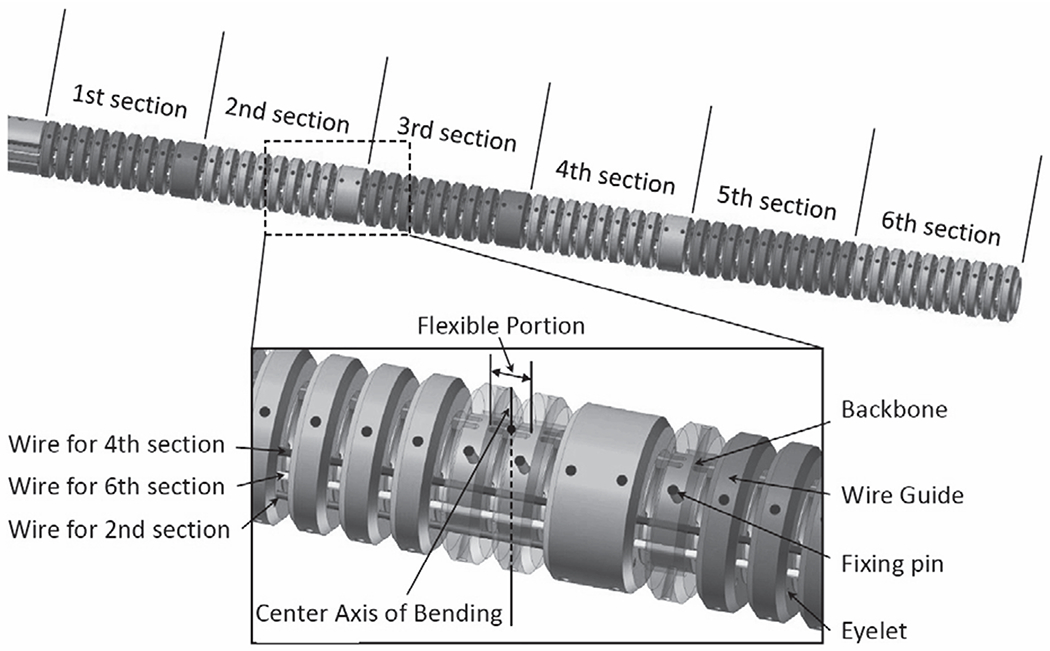
3D CAD model of the continuum robot
1). Backbone tube:
The backbone is a monolithic elastic tube made of Nitinol and includes flexible and rigid portions periodically spaced along its length by cutting out the tube wall with laser. The wall thickness of the tube is 0.2 mm with outer diameter of 2.2 mm. The cutting outs parts create antagonistic pair of leaf springs at remaining parts between the adjacent rigid portions. This antagonistic pair of the leaf spring has anisotropic bending stiffness in in-plane direction from out-of-plane direction to suppress undesired out-of-plane motion. These flexible portions cause the backbone to act as a set of tandem rotational springs. The push-pull wires (mentioned below) are fixed to the backbone by small pins and are glued to the push-pull wires at the distal end of each section.
2). Wire guides:
The wire guides to house the push-pull wire are made of polyether ether ketone (PEEK) by CNC machining. Total of Six wire guides through eyelets in the wire guides. The wire guides are spread apart, each at 1.4 mm from the centroid of the robot. Fig. 1 depicts the push-pull wires for the 2nd, 4th and 6th bending sections. The wire guides for the 6th section, which is on the bending plane, is fixed at the distal end of the robot. The other wire guides are fixed at the distal end of each section. The wire guides for the 1st, 3rd and 5th bending sections are aligned in the same way on the other side of the robot. The push-pull wires on the wire guides are terminated at the distal end of each section; the six bending sections can be manipulated independently. The wire guides are aligned with the rigid portions of the backbone by using the fixing pins. The fixing pins have the length of 0.8 mm with the diameter of 0.2 mm, and define both longitudinal and circumferential positions of the wire guides for the rigid portions so that bending moments are applied only at the rigid portions to in-plane direction.
3). Push-pull wires:
The push-pull wires are made of stainless steel and has a diameter of 0.15 mm. The push-pull wires are supported by the wire guides and travels through free space of 0.25 mm only between the gap of the adjacent wire guides. This short travel distance in free space renders the push-pull wires to prevent buckling in pushing operation.
4). Kinematic models:
To enable control of the robot, kinematic models that capture the relationship among the bending angles, the pushing/pulling displacement on the push-pull wires and the displacements of the section tip must be established. The notations used for this purpose are defined below.
ln : Length of nth section.
rn : Distance between the centroid of the robot and the push-pull wire of the nth section projected onto the xz plane.
e : Number of sections of the robot,
θn : Bending angle of nth section.
ρn : Radius of curvature of the nth section.
lpn : Pushing/pulling displacement on the push-pull wire for the nth section.
xtn, ztn : Displacement of the tip of the nth section.
c : Number of evaluation points used to calculate the FTL motion plan.
xrefi, zrefi : ith displacement when the robot is divided into c evaluation intervals.
zb : Displacement of the proximal end of the robot.
The frame of reference oxz-axis was attached to the trocar with oz-axis being the directional vector of the trocar. Then the lateral axis of the motion plane, or ox-axis, was set as positive direction of the x being the posterior side of subjects.
The following assumptions are adopted:
The robot deforms only in the xz plane.
Each section bends into a circular shape.
The torsional deformation of the robot is negligible.
The robot does not extend or contract in the longitudinal direction.
Frictional effects such as those between the wire guides and wires are negligible.
Fig. 2 shows the model of a single section of the robot. The relationship between the pushing/pulling displacement lp1 and the bending angle of the first section is
| (1) |
where l1 is
| (2) |
Fig. 2.
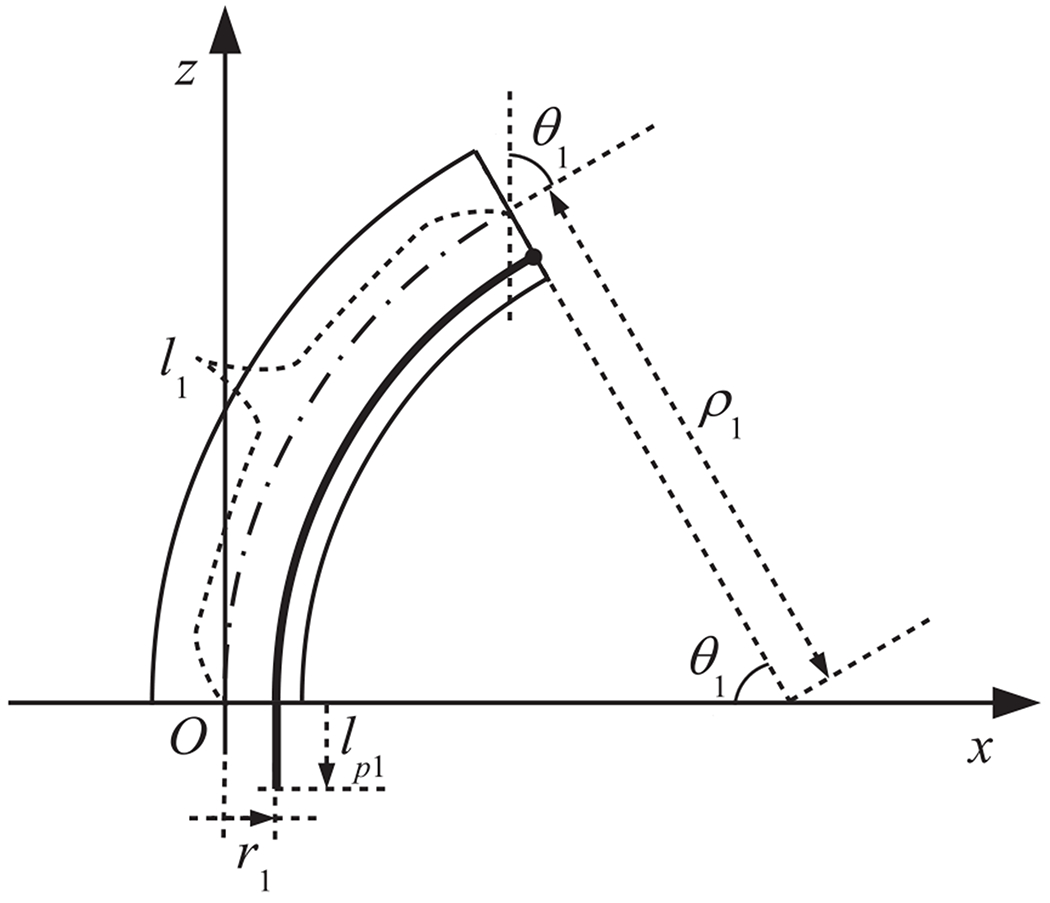
Model of a single section
Hence, when the bending angle of the 1st section is known, the pushing/pulling displacement can be derived as follows:
| (3) |
Now, we will derive the relationship between the pushing/pulling displacement lpn and the bending angle of the nth section (n ≤ 2). In this paper, we define the relative angle between the nth and n − 1th sections as follows:
| (4) |
We introduce the relative xnzn coordinate systems for the nth section as shown in Fig. 3, where the origin is (xtn−1, ztn−1), the zn axis is aligned with the direction tangential to the distal end point of the n − 1th section, and the xn axis is orthogonal to the zn axis. The pushing/pulling displacement in the relative xnzn coordinate system is
| (5) |
Fig. 3.
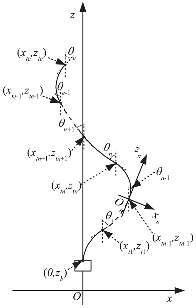
Model of multiple sections
Hence, the pushing/pulling displacement lpn can be computed as follows from the sum of the pushing/pulling displacement for the 1st to nth sections:
| (6) |
The bending angle of the nth section, θn is determined only by the pushing/pulling displacement lpn, without any dependence on the intervening shape of the robot.
Next, we derive the displacement of the tip of the nth section. The tip displacement () in the relative xnzn coordinate system is
| (7) |
| (8) |
The tip displacement (xtn, ztn) of the nth section in the absolute coordinate system is obtained as below using the corresponding rotation matrix:
| (9) |
where the rotation matrix Rm−1 is
| (10) |
Moreover, as described in the following section addressing the computational procedure for FTL motion planning, c evaluation points are used for the optimization algorithm. The interval of evaluation points is α times shorter than the length of each section. Thus, the total number of evaluation points is
| (11) |
The ith evaluation point (xrefi, zrefi) is given as follows:
If i < α,
| (12) |
where R is modulo for dividend i and divisor α calculated as R = i mod α.
If i = n α,
| (13) |
, where Q is quotient for dividend i and divisor α.
If i = i = nα + 1, …, nα + α − 1,
| (14) |
where pb is
| (15) |
5). Actuation system:
Fig. 4 and 5 show a schematic diagram and photographs of the robotic system. The actuator unit contains a tractor unit and motor drive circuits (maxon EPOS2 24/2 digital positioning controllers). In the tractor unit, the push-pull wires are connected to drive nuts, as shown in the upper-right photograph in 5. When the six motors (maxon EC-max 16 brushless motors) drive the screws, the drive nuts push or pull the push-pull wires by moving along the z-axis. The actuator unit is mounted on a linear stage (HIWIN PGHW20CC) that is integrated with a magnetic encoder for position measurement. The FTL control algorithm is implemented in a digital signal processor (DSP) (A&D AD7011-EVA). We transfer the FTL motion data, which are calculated as described in the following section, from the PC to be stored on the DSP. The DSP outputs reference signals for the pushing/pulling displacement lpn to be applied to the push-pull wires for the n section in accordance with the displacement zb of the proximal end of the robot. The DSP is connected to a joystick, whose signal is added to the pushing/pulling displacement for the 6th section. This joystick enables the operator to look around during FTL motion.
Fig. 4.
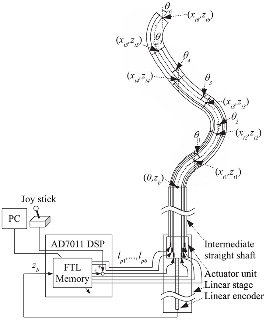
Schematic diagram of the robotic system
Fig. 5.
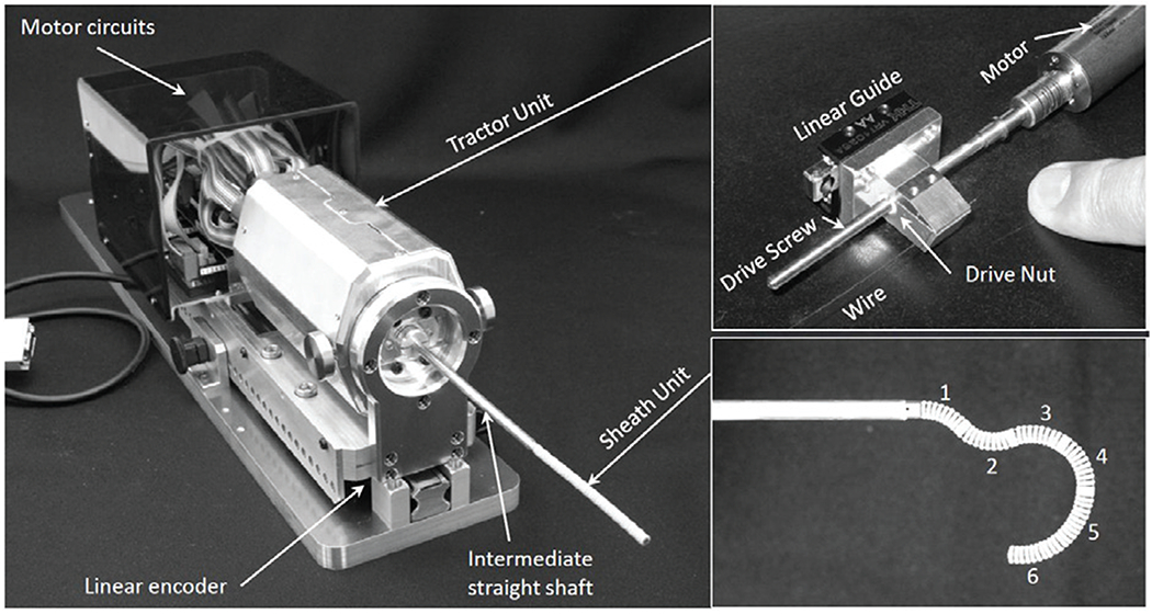
Photographs of the robotic system
B. FTL motion planning
1). Surgical path planning with 3D Slicer:
For a combined ETV/ETB procedure, a burr hole is created on the floor of the lateral cerebral ventricle using a trocar passing through the frontal bone of the skull. The position of the burr hole is chosen in accordance with the convention of using Kochers point (25 mm lateral to the sagittal suture, 10 mm anterior to the coronal suture) [18]. Through the trocar, an instrument is introduced into the ventricular space through the FM and toward the ETV/ETB targets, as shown in Fig. 6.
Fig. 6.
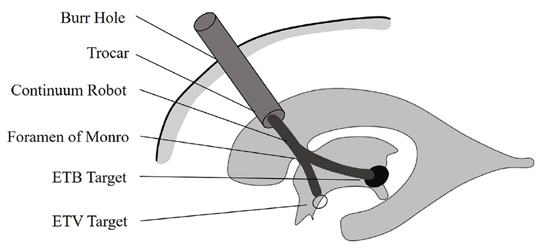
Continuum robot for a combined ETV/ETB procedure
Anatomical models of the skull, cerebral ventricles, and tumors are obtained using the 3D Slicer software package (http://www.slicer.org) by importing the patients MRI data. The ventricular system is filled with clear and watery CSF, which allows the boundary to be reliably visualized and segmented using T1- and T2- weighted sequences. After the acquired surface is smoothed using a Laplacian smoother, the patient’s MRI image is segmented by using the 3D Slicer software package to create a virtual 3D hydrocephalic ventricular system, including the lateral, third and fourth ventricles. All image manipulation and planning were performed in patient coordinate system derived from the T1 and T2 images.
In the segmented ventricular model, the anatomical landmarks include the surgical incision in the lateral cerebral ventricle, the surgical target, the FM region and the ETV site, as shown in Fig. 7. The surgical incision is modeled based on the position of the burr hole and the orientation of the trocar. The FM region, a narrow region in the cerebral ventricle, is represented as a cylindrical region with a specified center point and with the center point and tolerant radius. The surgical target represents the acceptable surgical target site for tumor biopsy. The ETV site is the region where an opening is created in the floor of the third ventricle to drain the CSF within the brain. Using the Measurements and Markups module of 3D Slicer, the clinician can represent these anatomical structures as planar circular regions that correspond to the FM, the floor of the third ventricle, and the target region for tumor biopsy to be used for surgical planning.
Fig. 7.
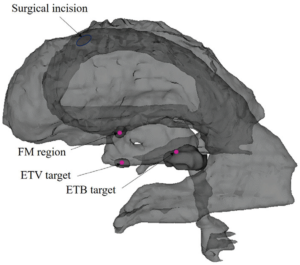
Anatomical landmarks in the ventricular model
Here, we assume that the continuum robot can be navigated along a 2D planar pathway from the surgical incision to each target within the ventricles. The motion plane is constructed based on the surgical incision, the FM region and the target site. In all paths, the position and direction of the surgical incision are selected to avoid damage to the motor areas in the brain. Using the 3D Slicer Measurements and Markups module, the fiducial markers of interest in the motion plane are selected to guide the robot safely through the FM region to the target (the last fiducial marker), as shown in Fig. 8. Board certified neurosurgeon (NS) supervised the engineering faculty (NH) to placement of the fiducial markers of interest in the motion plane. The tolerant radius of the FM region loosen the constraints on the selection of the motion plane and the optimal pathways by allowing for a larger acceptable space. The avoidance of anatomical collision is the most important criterion for the selection of fiducial markers.
Fig. 8.
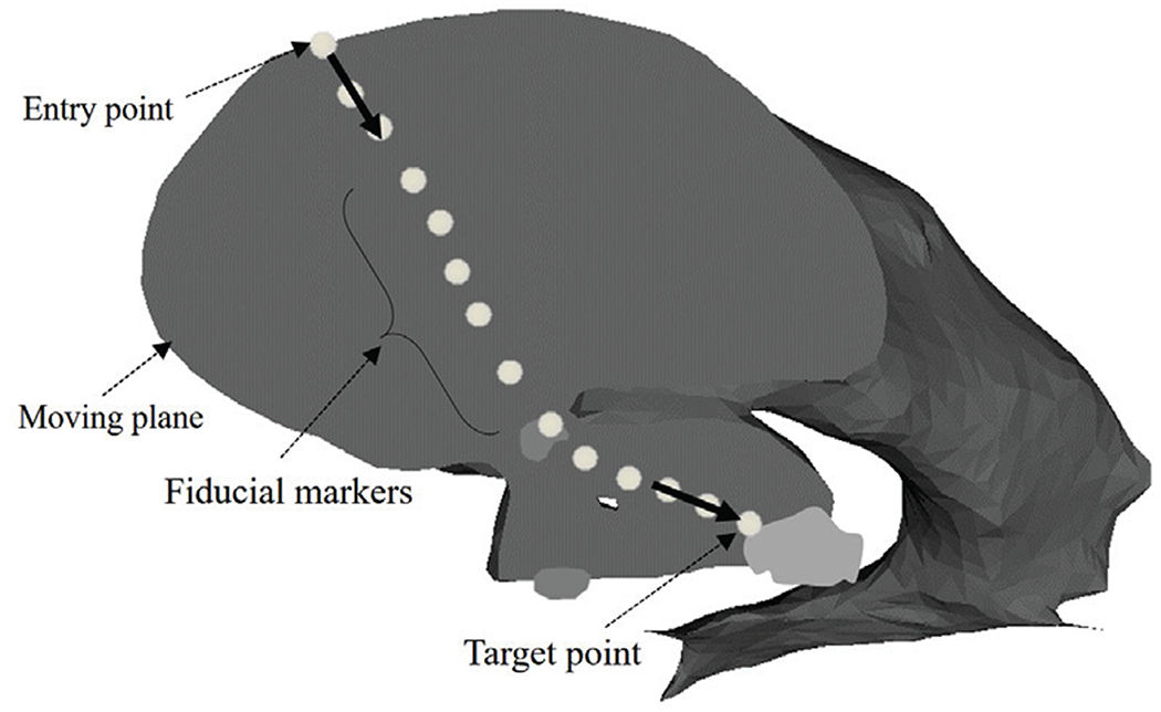
Selected fiducial markers specified on the anatomical model of a hydrocephalic ventricle
2). Computational procedure for FTL motion planning:
First, we convert the discrete fiducial markers into a constant-speed splined curve 9. Because the length of the robot is 60 mm, the length of the pathway along which the robot can move forward under FTL control is equal to the distance along the pathway toward the target that is indicated by the solid line in 9. Second, we interpolate from the discrete fiducial markers to calculate the constant-speed splined curve. We set the distance between interpolated points on the splined curve to 0.25 mm. Third, we perform the necessary calculations to conform the robot’s pose to the trajectory obtained as described in 9.
We set the total number of evaluation points to c = 240. We introduce trajectory points denoted by xtra1~240, ztra1~240, which form a path with a total length of 60 mm and are cropped from the constant-speed splined curve. The bending range of bending angle was ±90 degrees. The displacement was set to 60 mm. The variable used in the simulation were illustrated in Figure 10. The solid line represents the robot’s pose, and the dashed line represents the interpolated trajectory. The black dots indicate the evaluation points defined in section II-A and the white dots indicate the cropped trajectory. The calculation algorithm is summarized as follows:
The displacement of the proximal end of the robot, zb, is set to zero.
240 trajectory points (xtra1~240, ztra1~240) are cropped from the constant-speed splined trajectory corresponding to the base position zb of the robot.
The robot angles θ1~6 are temporarily set to zero. 240 robot evaluation points (xref1~240, zref1~240) are calculated according to (12) to (14).
- The robot angles θ1~6 are calculated by using the method of steepest descent to fit the trajectory points. The criterion for evaluation is as follows:
(16) The displacement of the proximal end, zb, is incremented by 0.25 mm, and the algorithm returns to step 2.
Fig. 10.
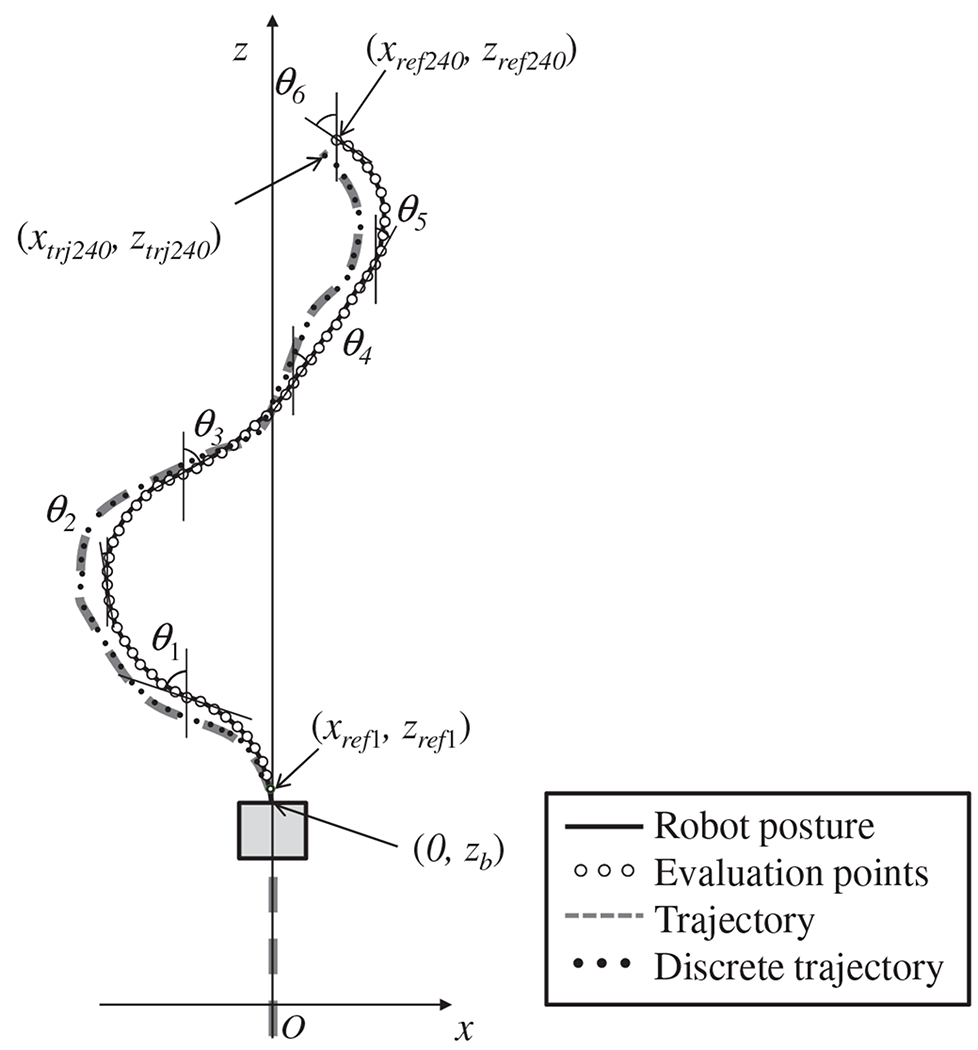
Variable definitions for fitting the robot’s pose
III. Experiments and Results
To validate the performance of our proposed FTL motion planning method and our prototype software and hardware, three experiments were conducted. The first test is entitled “Accuracy test in elementary-shaped paths” validating the accuracy of FTL motion planning along elementary curved paths, namely ‘S’ and ‘C’ bends; the purpose of test was to investigate the core mechanical performance of the robot. In this first experiment and in the subsequent ones, the accuracy was evaluated based on the deviation of the actual path achieved by the actuated robot against the FTL-path. second, we also measured the accuracy of FTL motion plans for reaching critical anatomical targets in simulated simultaneous ETV/ETB procedures using data from a real clinical subject who had previously undergone ETV/ETB operation. This second study is entitled ‘FTL motion accuracy test on ETV/ETB paths’.
The data analysis scheme was performed as follows. The actual paths of the actuated robot and the corresponding FTL paths were recorded in all three experiments. The robot was positioned with its bending plane aligned horizontally and was actuated three times for each path. The averaged locations of the midpoints of the sixty cells along the robot’s body across all three trials, which were observed from a measurement camera using a grid paper, were used to represent the shape of the robot. By comparing these actual locations against the planned locations, the accuracy of the FTL motion plans was evaluated, as discussed in the following three experiments.
A. Accuracy test on elementary-shaped paths
The purpose of the first study was to validate how well the FTL motion plans were achieved in elementary curved paths. This was done by maneuvering the robot along the elementary paths using the corresponding FTL motion plans and measuring the deviation of the robot’s actual path against the desired path. The elementary curved paths tested in our study were C-bends and S-bends. For C-bends, paths requiring continuous bending of the robot’s bending sections with constant angles between 0° and 180° at 30° intervals were tested. For S-bends, three patterns were prepared to represent curves with varying degrees of acuteness in curves. The first bending pattern consisted of two acute curves in opposite directions, requiring the bending of two of the six bending sections of the robot. The second pattern represented milder acute curving, with gradual bending of four of the six bending sections. Similarly, in the third pattern, all six sections were bent to mimic the most gradual and least acute bending scenario. In all patterns, the distal end of the robot was aimed straight ahead.
Choset et al. defined the FTL as ”the shaft exactly follows the path through space traced by the tip of the device” [19]. We recognize, therefore, the error of FTL operation can be measured as deviation of the sections following the tip of the robot from the planned FTL-path. In [20], this deviation is defined as was the averaged of the distances d between each of the measured midpoints along the robot and the corresponding desired points on the planned path. Thus d can be computed as,
| (17) |
where nt is the number of measured points. Student’s t-test was used to compare the robot’s shape deviations d among the measurements for each pattern. The criterion for a significant difference was set to p < 0.05. All data were analyzed using MATLAB R2014a.
Fig. 11(a) shows the results for the deviations on C-bend paths. The robot’s shape deviation d gradually increased from 0.47 mm at 30° to 1.78 mm at 180°. The deviation of the actual path against the planned FTL path increased with the bending angle of the path, especially for bending angles greater than 90°. A statistical comparison of the robot’s shape deviations d indicated statistically significant differences among the deviations on these C-bend paths, with p < 0.0001.
Fig. 11.
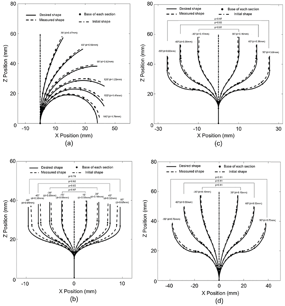
Path deviations for (a) C-bends, (b) 2-section S-bends, (c) 4-section S-bends, and (d) 6-section S-bends
Fig. 11(b) shows the deviation results for 2-section S-bend paths. The number of measured points, nt, along the two bending sections was 20. The robot’s shape deviation d gradually increased from 0.08 mm at 15°, to 0.67 mm at 60°. A statistical comparison of the robot’s shape deviation d indicated statistically significant differences among the deviations for the 2-section S-bends with angles of 60°, 45°, 30° and 15°, with p < 0.0001. The values of p shown in Fig. 11(b) represent the differences between symmetrical bending curves.
Fig. 11(c) shows the deviation results for 4-section S-bend paths. The number of the measured points, nt, along four bending sections was 40. The robot’s shape deviation d gradually increased from 0.16 mm at 30° to 0.69 mm at 90°. A statistical comparison of the robot’s shape deviations d indicated statistically significant differences among the deviations for the 4-section S-bends with angles of 90°, 60° and 30°, with p < 0.0001.
Fig. 11(d) shows the deviation results for 6-section S-bend paths. The number of measured points, nt, along six bending sections was 60. The robot’s shape deviation d gradually increased from 0.16 mm at 30° to 0.75 mm at 90°. A statistical comparison of the robot’s shape deviation d indicated statistically significant differences among the deviations for the 6-section S-bends with angles of 90°, 60° and 30°, with p < 0.0001.
In a comparison of the 2-section, 4-section and 6-section S-bends with 60° bending angles, the deviation is seen to be significantly larger for the 2-section S-bends (d=0.67 mm) than for the 4-section (d=0.38 mm) and 6-section (d=0.52 mm) S-bends, with p < 0.0001. There is no significant difference among the deviations of the robot’s shape for 2-section (d=0.18 mm), 4-section (d=0.16 mm) and 6-section (d=0.16 mm) S-bends with 30° bending angles, for which p=0.54.
B. FTL motion accuracy test on a representative ETV/ETB procedure
The motivation for this second study was to validate whether the robot could reach the critical anatomical targets that a physician might wish to observe or treat by using FTL motion.
In this and the subsequent clinically relevant tests, a hydrocephalic ventricle segmented from the MRI data of a subject (male, 53 years old, a mass in the third ventricle, ETV/ETB, high-grade astroscytoma) was used. We selected surgical targets that are liable to cause obstructive hydrocephalus, including an ETV site and four typical ETB sites, as listed in Table I. From these ETV/ETB sites, Slicer Path were generated in the hydrocephalic ventricle by Slicer.
TABLE I.
Target locations in the five considered cases
| ETV/ETB Paths | Target location |
|---|---|
| Path 1 | ETV site |
| Path 2 | Floor of the third ventricle |
| Path 3 | Cerebral aqueduct of the fourth ventricle |
| Path 4 | Pineal region |
| Path 5 | Posterior region of the third ventricle |
Then these Anatomical Path were provided to the actuated system to create five sets of FTL-path described in Section II(A), as shown in Fig. 12 for the five paths created. In laboratory experiments, the distal end of the robot was then advanced from the start point to the end point on each FTL-path, and the proximal end of the robot was moved along the linear guideway. We measured the shape of the entire robot at every 5 mm of advancement of the robot (collectively called Measured Path).
Fig. 12.
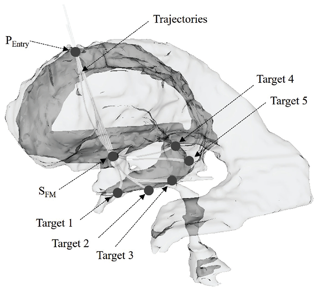
The hydrocephalic ventricle with surgical targets
In the analysis, the tip deviation was validated by measuring distance between the measured position of the tip of the actuated robot in Measured Path, and the corresponding tip position in the Anatomical Path. To analyze the source of the tip deviation, two other types of tip deviation were defined, as follow. First, the theoretical tip deviation is defined as the distance between the tip position on the Anatomical Path and the corresponding tip position on the FTL-path. Second, the actuated tip deviation is defined as the distance between the actual position of the tip in Measured Path and the corresponding tip position on the FTL-path. Three types of deviations of the robot’s shape were also defined for deviation analysis. The robot’s shape deviation is calculated as shown in (17), and the calculated shape deviation and the actuated shape deviation are similarly calculated from the Anatomical Path, the FTL-path and Measured Path.
Fig. 13 shows the deviation results for case 1. The calculated tip deviation and the calculated shape deviation tend to be steady along the advancement. The maximal tip deviation is 0.88 mm when the advance distance is 50 mm, and the maximal robot’s shape deviation is 0.87 mm when the advance distance is 60 mm. The deviations tend to accumulate as the robot advances. Fig. 14 shows the deviation results for Path 2. The actuated tip deviation increases obviously to 0.65 mm when the advance distance is 40 mm where a sharp bend occurs. The robot’s shape deviation shows a slight increase as the robot advances.
Fig. 13.
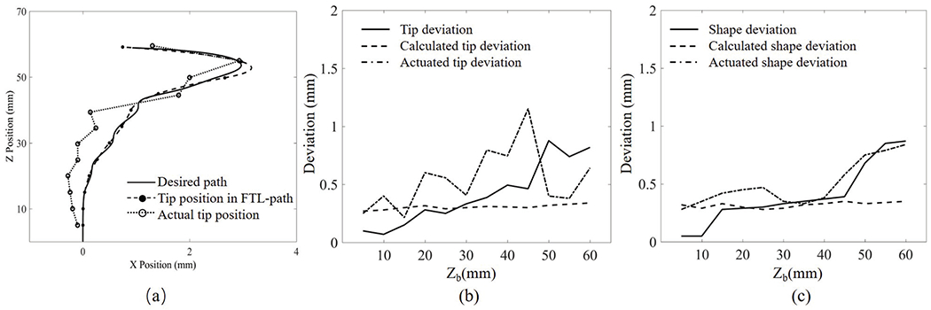
Robot path in Path 1: (a) tracked position of the robot’s tip, (b) tip deviation, and (c) shape deviation. X position and Z position are the displacement of the robot in the moving plane; Zb is the displacement of the proximal end of the robot
Fig. 14.

Robot path in Path 2: (a) tracked position of the robot’s tip, (b) tip deviation, and (c) shape deviation. X position and Z position are the displacement of the robot in the moving plane; Zb is the displacement of the proximal end of the robot
C. Potential collision test on ETV/ETB paths
Third, using the same subject and hypothetical clinical scenario as in the second study, we tested the surgical safety of the robot by measuring the extent to which the actual path might deviate beyond ventrical wall, indicating trauma to the ventricle. This third test is entitled “Potential collision test on ETV/ETB paths”.
To examine the potential for collision as the continuum robot is navigated along a torturous pathway, the contact displacement between the ventricular wall and the robot’s path was measured for each of the five ETV/ETB paths. The robot’s pose was recorded after every 5 mm advance from the origin toward the target. The outer diameter of the robot was considered when representing the outline of the robot’s pose. By overlaying these poses, an envelope was created to represent the robot’s measured path. The boundary of the hydrocephalic ventricular system was extracted in MATLAB, and the origin of the robot path and the position of the surgical incision are registered.
Fig. 15 shows the actual robot paths and ventricular boundaries for the five paths, providing a visualization of the relative positions and locations where the collisions or narrow paths could potentially occur during the FTL motion. There is no collision between the ventricular wall and the actual path of the actuated robot in any cases except Path 3. The shortest distances between the actual path and the ventricular boundary are 2.47 mm in Path 1, occurring near the FM region; 0.23 mm in Path 2, also occurring near the FM region; 1.02 mm in Path 4, again occurring near the FM region; and 0.31 mm in Path 5, occurring near the third ventricular region. In Path 3, there is a collision between the ventricular wall and the actual path that results in a 0.62 mm displacement near the third ventricular region.
Fig. 15.
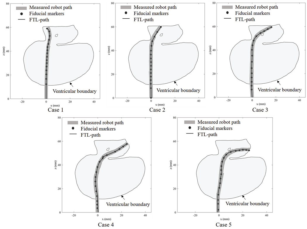
Robot paths through the ventricular system in the five investigated paths
IV. Discussion
In this study, we have presented a continuum robot controlled using an FTL motion planning for an endoscopic ETV/ETB procedure. The aim of this method is to reach the surgical target while avoiding collisions with the anatomy. The accuracy of such FTL motion plans along elementary curved paths and on simulated ETV and ETB paths were experimentally validated. In the accuracy test of elementary-shaped paths, the shape deviations of the robot were within 1.78 mm. In the FTL motion plan accuracy test on ETV/ETB paths, the deviations of the distal end of the robot were within 1.49 mm, and the shape deviations were within 1.32 mm. In the potential collision test on ETV/ETB paths, a collision of the robot with the anatomy was found to occur in one path, with a displacement of 0.62 mm, whereas no collisions were found in the other cases.
For C-bends in the accuracy test of elementary-shaped paths, the position deviation of the distal end of the robot increases as the bending angle increases. Moreover, among the six bending sections, the section located at the proximal base of the robot exhibits smaller deviations than that located at the distal end. For 2-section S-bends with bending angles of 60, the shape deviation of the robot is obviously larger than it is for other bending angles, possibly because this shape is close to the limiting bending angle of each section, resulting in a large deviation. The results are in concordance with that in reference [21], [22], [23]. Hysteresis operation may also contribute to explaining this result, as we have discussed in reference [21]. Another reason might be the friction effect of the driven tendons. Friction, which depends on the cable length and bending angles, changes the tension distribution along the longitudinal direction of the robot, which reported in reference[24], [25]. Therefore, this variation in the tension distribution may result in a systematic tip position discrepancy.
In the FTL motion plan accuracy test on ETV/ETB paths, a deviation between the measured trajectory and the FTL trajectory accumulates as the robot advances; this might be explained by an accumulation of the deviation over time. In Path 4 and 5, the shape deviations of the robot are obviously larger than those in Path 1, 2 and 3. This may be because the curves in these two paths are sharper than in others. These findings also reveal that the position deviation of the robot increases as the length of the moving part of the robot increases. The analysis indicates that the deviation between the FTL path and the desired curve predominantly depends on the FTL motion planning method and the limitations of the bending angle; by contrast, the deviation between the robot’s measured path and FTL path is probably related to the uncertainty in the control inputs and the kinematic model of the robot. According to [1], [2], [26], a target position from a tumoral area of 2 cm is resectable. For the five paths investigated here, the mean deviation of the distal end in the in-plane direction is 0.563 mm, and that in the direction normal to the plane is 0.321 mm; these results indicate the potential reliability of the FTL motion planning method for use in ETV/ETB operations.
The motion planning for FTL includes the process to incrementally advance the robot and find optimal combination of the bending angles θ1~6 to fit the shape of the robot to the clinically ideal trajectory. Although it is unlikely, there is a chance that the optimization process falls in to local minima causing the planned path to deviate further away from the clinical path. Further investigation is warranted to investigate the occurrence of the optimization process converging to local miminima and its impact on path planning.
A continuum robots with FTL motion have been presented by others. Simaan et al presented a robot for use in cochlear implant surgery and transurethral surveillance and intervention [27], [28], [29], [30]. However, despite these promising studies, it remains challenging for a multisection continuum robot to provide high dexterity while simultaneously follow the precise transventricular multicurved trajectory required for the ETV/ETB procedure.
ETV/ETB is performed using either rigid or flex (or both) endoscope(s) from one or two burr hole(s) placed on the calvarium [31], [2], [8].Since a rigid endoscope is operated in a single-dimensional fashion and a flex endoscope, two-dimensional. It is noteworthy that Eastwood et al. depicted the feasibility of planar motion in single-burr-hole ETV/ETB utilizing virtual reality environment [9]. Also, as pointed out in the literature by Zhu et al., some displacement in cerebral structures seems to be permissible [5].
The robot presented in the study can mount miniature camera parts used endoscope. The validation study presented in the article was conducted without mounted the endoscopic camera to investigate the performance of the follow-the-leader motion. The further study is suggested to validate the performance of follow-the-leader motion while mounting the endoscopic camera.
The approximated average time to complete the task from the burr hole entry to the target is 45 minutes in our experiment. This is slightly longer than the time an experience physicians would need to reach the targets. When the abnormal anatomy exists in the approaching path, which is often this technology is helpful, the time required to reach the tumor and bottom of ventricular wall is significantly higher. In other words, the robot will speed up or even enables the ETV/ETB procedure in the presence of abnormal anatomy.
In the potential collision test on ETV/ETB paths, the results also show that the shortest distance between the robot and the ventricular boundary often occurs near the FM region, which indicates that the FM region is a potential collision region. The geometry of the FM region limits the choice of ETV/ETB paths in the anterior position because of the need to avoid injury to the fornix and in the posterior position because of the need to avoid injury to the venous angle and genu of the internal capsule [4]. As reported in [5], the mean FM diameters of measured from the axial, coronal, and sagittal views were 5.7 mm, 7.8 mm, and 5.6 mm, respectively, and it was found that maximum FM displacements of 4.8 mm (anterior) for ETV and 5.5 mm (posterior) for ETB are likely to be safe. As seen from the results of the current study, in Path 3, the collision occurs with a displacement of 0.62 mm, which is much less than the maximal safe FM displacement. In this experiment, we considered five ETV/ETB paths for surgical targets located near the pineal region and the posterior third ventricular region; however, the applied method could also probably be extended to other surgical targets in the ETV/ETB procedure.
When moving along a tortuous pathway, the entire robot, not only the distal end, has the possibility to collide with the ventricle. Therefore, the objective of the FTL motion planning computation is to minimize the distance between the robot path and the desired trajectory, with no greater priority placed on minimizing the deviation of distal end. In this newly developed robotic system, once the robot has advanced close to the surgical target, the last section could be manipulated using the joystick to achieve a pitch rotation. This design compensates for the position discrepancy of the distal end with respect to the surgical target in the horizontal plane.
As seen from the experiments, the accuracy of an FTL-path depends on the length of the moving part of the robot and the curvature of the bending sections. The reason for this dependency might be that the flexibility of the robot increases as the length of the moving part and the bending angle increase. Another possibility is that the position deviation near the base of the robot accumulates over the length of the robot and is amplified at the distal end. Therefore, minimizing the length of the moving part of the robot and maximizing the radius of curvature could be beneficial for robot design and FTL motion planning. The variable-curvature multisection design of the robot minimizes the number of sharp bends in order to decrease the position deviation of the distal end. With the proposed FTL motion planning method, two tortuous pathways for a continuum robot can be generated for a combined ETV/ETB procedure through one surgical incision.
V. Conclusion
This paper presented the use of a continuum robot was proposed using an FTL motion planning to perform a combined ETV/ETB procedure with anatomical and surgical task constraints. The validatin study showed the proposed method can generate effective multicurved pathways to the surgical targets in a combined ETV/ETB procedure. We expect that the proposed FTL motion planning concept will lead to the widespread use of wire-driven continuum robots to navigate tortuous pathways with the flexibility necessary for neuroendoscopy in neurosurgery [2].
Fig. 9.
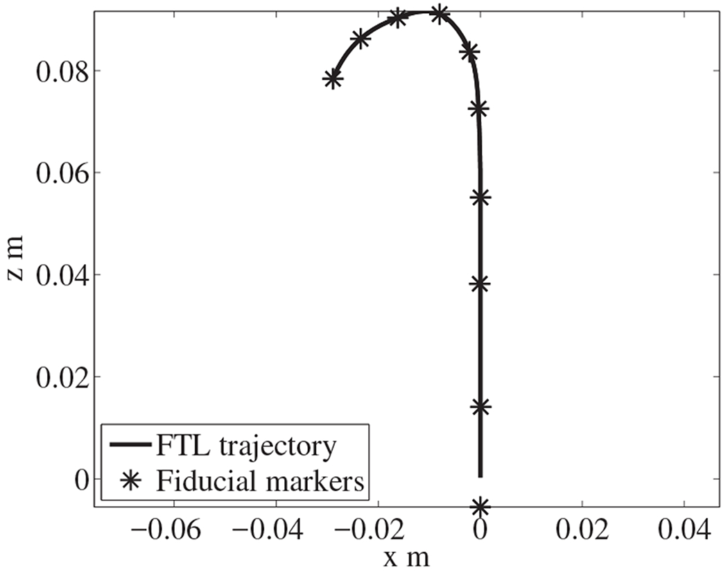
Converting discrete fiducial markers into a trajectory
Contributor Information
Yuanqian Gao, National Center for Image Guided Therapy, Brigham and Women’s Hospital and Harvard Medical School, Boston, MA, USA; Department of Mechanical Engineering, Tianjin University, Tianjin,300072 China.
Kiyoshi Takagi, Mechanical Development Department 31, Canon Inc., Japan.
Takahisa Kato, National Center for Image Guided Therapy, Brigham and Women’s Hospital and Harvard Medical School, MA, USA; Healthcare Optics Research Laboratory, Canon U.S.A., Inc., MA, USA.
Naoyuki Shono, National Center for Image Guided Therapy, Brigham and Women’s Hospital and Harvard Medical School, MA, USA.
Nobuhiko Hata, National Center for Image Guided Therapy, Brigham and Women’s Hospital and Harvard Medical School, MA, USA.
References
- [1].Feletti A, Marton E, Fiorindi A, and Longatti P, “Neuroendoscopic aspiration of tumors in the posterior third ventricle and aqueduct lumen: A technical update,” Acta Neurochirurgica, vol. 155, no. 8, pp. 1467–1473, 2013. [DOI] [PubMed] [Google Scholar]
- [2].Chibbaro S, Di Rocco F, Makiese O, Reiss A, Poczos P, Mirone G, Servadei F, George B, Crafa P, Polivka M, and Romano A, “Neuroendoscopic management of posterior third ventricle and pineal region tumors: technique, limitation, and possible complication avoidance,” Neurosurgical Review, vol. 35, no. 3, pp. 331–340, 7 2012. [DOI] [PubMed] [Google Scholar]
- [3].Ahmed AI, Zaben MJ, Mathad NV, and Sparrow OC, “Endoscopic biopsy and third ventriculostomy for the management of pineal region tumors,” World Neurosurgery, vol. 83, no. 4, pp. 543–547, 4 2015. [DOI] [PubMed] [Google Scholar]
- [4].Morgenstern PF, Osbun N, Schwartz TH, Greenfield JP, Tsiouris AJ, and Souweidane MM, “Pineal region tumors: an optimal approach for simultaneous endoscopic third ventriculostomy and biopsy,” Neurosurgical Focus, 2011. [DOI] [PubMed] [Google Scholar]
- [5].Zhu XL, Gao R, Wong GKC, Wong HT, Ng RYT, Yu Y, Wong RKM, and Poon WS, “Single burr hole rigid endoscopic third ventriculostomy and endoscopic tumor biopsy: What is the safe displacement range for the foramen of Monro?” Asian Journal of Surgery, vol. 36, no. 2, pp. 74–82, 4 2013. [DOI] [PubMed] [Google Scholar]
- [6].Pettorini BL, Al-Mahfoud R, Jenkinson MD, Avula S, Pizer B, and Mallucci C, “Surgical pathway and management of pineal region tumours in children,” Child’s Nervous System, vol. 29, no. 3, pp. 433–439, 3 2013. [DOI] [PubMed] [Google Scholar]
- [7].Knaus H, Matthias S, Koch A, and Thomale UW, “Single burr hole endoscopic biopsy with third ventriculostomy-measurements and computer-assisted planning,” Child’s Nervous System, vol. 27, no. 8, pp. 1233–1241, 8 2011. [DOI] [PubMed] [Google Scholar]
- [8].Roth J and Constantini S, “Combined rigid and flexible endoscopy for tumors in the posterior third ventricle,” Journal of Neurosurgery, vol. 122, no. 6, pp. 1341–6, 6 2015. [DOI] [PubMed] [Google Scholar]
- [9].Eastwood KW, Bodani VP, and Drake JM, “Three-dimensional simulation of collision-free paths for combined endoscopic third ventriculostomy and pineal region tumor biopsy: Implications for the design specifications of future flexible endoscopic instruments,” Operative Neurosurgery, vol. 12, no. 3, pp. 231–238, 9 2016. [DOI] [PubMed] [Google Scholar]
- [10].Barber SM, Rangel-Castilla L, and Baskin D, “Neuroendoscopic resection of intraventricular tumors: A systematic outcomes analysis,” 2013. [DOI] [PMC free article] [PubMed]
- [11].Webster III RJ and Rucker DC, “Statics and Dynamics of Continuum Robots With General Tendon Routing and External Loading,” Robotics, IEEE Transactions on, vol. 27, no. 6, pp. 1033–1044, 2011. [Google Scholar]
- [12].Swaney PJ, Gilbert HB, Webster RJ, Russell PT, and Weaver KD, “Endonasal skull base tumor removal using concentric tube continuum robots: A phantom study,” Journal of Neurological Surgery, Part B: Skull Base, vol. 76, no. 2, pp. 145–149, 2015. [DOI] [PMC free article] [PubMed] [Google Scholar]
- [13].Bergeles C, Gosline AH, Vasilyev NV, Codd PJ, Del Nido PJ, and Dupont PE, “Concentric tube robot design and optimization based on task and anatomical constraints,” IEEE Transactions on Robotics, vol. 31, no. 1, pp. 67–84, 2015. [DOI] [PMC free article] [PubMed] [Google Scholar]
- [14].Burgner-Kahrs J, Rucker DC, and Choset H, “Continuum Robots for Medical Applications: A Survey,” pp. 1261–1280, 2015.
- [15].Ha J, Park FC, and Dupont PE, “Optimizing Tube Precurvature to Enhance the Elastic Stability of Concentric Tube Robots,” IEEE Transactions on Robotics, vol. 33, no. 1, pp. 22–37, 2017. [DOI] [PMC free article] [PubMed] [Google Scholar]
- [16].Du Z, Yang W, and Dong W, “Kinematics modeling and performance optimization of a kinematic-mechanics coupled continuum manipulator,” Mechatronics, vol. 31, pp. 196–204, 2015. [Google Scholar]
- [17].Ho M, McMillan AB, Simard JM, Gullapalli R, and Desai JP, “Toward a meso-scale SMA-actuated MRI-compatible neurosurgical robot,” IEEE Transactions on Robotics, vol. 28, no. 1, pp. 213–222, 2012. [DOI] [PMC free article] [PubMed] [Google Scholar]
- [18].Esposito F, Di Rocco F, Zada G, Cinalli G, Schroeder HWS, Mallucci C, Cavallo LM, Decq P, Chiaramonte C, and Cappabianca P, “Intraventricular and skull base neuroendoscopy in 2012: A global survey of usage patterns and the role of intraoperative neuronavigation,” pp. 709–716, 2013. [DOI] [PubMed] [Google Scholar]
- [19].Choset H and Henning W, “A Follow-the-Leader Approach to Serpentine Robot Motion Planning,” Journal of Aerospace Engineering, 1999. [Google Scholar]
- [20].Hannan MW and Walker ID, “Kinematics and the implementation of an elephant’s trunk manipulator and other continuum style robots,” Journal of Robotic Systems, vol. 20, no. 2, pp. 45–63, 2003. [DOI] [PubMed] [Google Scholar]
- [21].Kato T, Okumura I, Kose H, Takagi K, and Hata N, “Tendon-driven continuum robot for neuroendoscopy: validation of extended kinematic mapping for hysteresis operation,” International Journal of Computer Assisted Radiology and Surgery, vol. 11, no. 4, pp. 589–602, 2016. [DOI] [PMC free article] [PubMed] [Google Scholar]
- [22].Li Z and Du R, “Design and analysis of a bio-inspired wire-driven multi-section flexible robot: Regular paper,” International Journal of Advanced Robotic Systems, vol. 10, 2013. [Google Scholar]
- [23].Palmer D, Cobos-Guzman S, and Axinte D, “Real-time method for tip following navigation of continuum snake arm robots,” Robotics and Autonomous Systems, vol. 62, no. 10, pp. 1478–1485, 2014. [Google Scholar]
- [24].Agrawal V, Peine WJ, and Yao B, “Modeling of transmission characteristics across a cable-conduit system,” IEEE Transactions on Robotics, vol. 26, no. 5, pp. 914–924, 2010. [Google Scholar]
- [25].Palli G, Borghesan G, and Melchiorri C, “Modeling, identification, and control of tendon-based actuation systems,” IEEE Transactions on Robotics, vol. 28, no. 2, pp. 277–290, 2012. [Google Scholar]
- [26].Souweidane MM and Luther N, “Endoscopic resection of solid intraventricular brain tumors,” J Neurosurg, vol. 105, no. 2, pp. 271–278, 2006. [DOI] [PubMed] [Google Scholar]
- [27].Zhang J and Simaan N, “Design of Underactuated Steerable Electrode Arrays for Optimal Insertions,” Journal of Mechanisms and Robotics, vol. 5, no. 1, p. 011008, 2013. [Google Scholar]
- [28].Degani A, Choset H, Wolf A, and Zenati MA, “Highly articulated robotic probe for minimally invasive surgery,” in Proceedings - IEEE International Conference on Robotics and Automation, vol. 2006, 2006, pp. 4167–4172. [DOI] [PMC free article] [PubMed] [Google Scholar]
- [29].Tully S, Kantor G, Zenati MA, and Choset H, “Shape estimation for image-guided surgery with a highly articulated snake robot,” in IEEE International Conference on Intelligent Robots and Systems, 2011, pp. 1353–1358. [Google Scholar]
- [30].Kutzer MDM, Segreti SM, Brown CY, Taylor RH, Mears SC, and Armand M, “Design of a new cable-driven manipulator with a large open lumen: Preliminary applications in the minimally-invasive removal of osteolysis,” in Proceedings - IEEE International Conference on Robotics and Automation, 2011, pp. 2913–2920. [Google Scholar]
- [31].Chernov MF, Kamikawa S, Yamane F, Ishihara S, Kubo O, and Hori T, “Neurofiberscopic biopsy of tumors of the pineal region and posterior third ventricle: Indications, technique, complications, and results,” Neurosurgery, 2006. [DOI] [PubMed] [Google Scholar]


