Chemical boundary engineering expands the dimensionality of alloy design.
Abstract
For decades, grain boundary engineering has proven to be one of the most effective approaches for tailoring the mechanical properties of metallic materials, although there are limits to the fineness and types of microstructures achievable, due to the rapid increase in grain size once being exposed to thermal loads (low thermal stability of crystallographic boundaries). Here, we deploy a unique chemical boundary engineering (CBE) approach, augmenting the variety in available alloy design strategies, which enables us to create a material with an ultrafine hierarchically heterogeneous microstructure even after heating to high temperatures. When applied to plain steels with carbon content of only up to 0.2 weight %, this approach yields ultimate strength levels beyond 2.0 GPa in combination with good ductility (>20%). Although demonstrated here for plain carbon steels, the CBE design approach is, in principle, applicable also to other alloys.
INTRODUCTION
Stronger steels with high ductility are crucial for solving key challenges in lightweight transportation and safe infrastructures, as evidenced by the incredible amount of 1.8 billion tons produced every year. High-strength steels, especially those with an ultimate tensile strength beyond 2.0 GPa, generally require a high level of carbon [>0.4 weight % (wt %)] and/or expensive doping elements such as cobalt, nickel, and chromium (1–4). Yet, using a high carbon and doping content is not pertinent in construction steels due to weldability and cost constraints. Microstructures with high lattice defect densities serve instead as a better route toward lean, affordable, and strong steels (4–7). Among these defect types, grain boundaries (GBs) and phase boundaries (PBs), which are planar discontinuities in metallic crystals, are particularly efficient in tuning the mechanical response of polycrystalline materials (Fig. 1, A and B). Grain boundary engineering (GBE), e.g., modulating the quantity or arrangement of GBs/PBs, has been widely used to tailor the mechanical properties of advanced engineering materials (5–7). Yet, further enhancement of GB-related properties is limited by the instability (low thermal stability/high mobility) of these crystallographic planar interfaces when alloys are exposed to mechanical or thermal loads, causing, for instance, grain coarsening (7).
Fig. 1. Schematic illustration of a PB, a GB, and a CB.
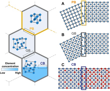
(A) PB, a boundary between two grains of different lattice type. (B) GB, a boundary between two grains of the same lattice type but with different crystallographic orientations. (C) CB, defined by a sharp discontinuity of at least one elemental concentration inside a lattice-continuous region, e.g., a very sharp chemical gradient. Note that our CBs do not involve any change in crystal structure or lattice orientation. The different colors represent atoms of different element type.
To expand the dimensionality of materials design, a not-yet fully explored type of planar defect, so-called chemical boundaries (CBs) is used here to architect novel microstructures that can act on the local phase transformation response of the material. CBs represent a very sharp chemical discontinuity inside a continuous lattice region, as shown in Fig. 1C. In our study, each CB is the residue of a former PB with its element partitioning retained upon removing the local change in crystal structure. Once formed, CBs act as strong barriers restricting subsequent phase transformations within ultrafine (submicron) domains. This methodology can result in a novel hierarchically heterogeneous microstructure consisting of martensite and austenite with nanoscaled laths and nanotwins, respectively, which can make it possible to achieve ultimate tensile strengths in excess of 2.0 GPa in combination with high ductility (>20%) in steels without high carbon content and/or doping expensive elements.
RESULTS
Initial microstructure with Mn heterogeneity
Among all metallic materials, steels are the most widely used ones, and their phase transformation behavior is well explored (8). Thus, they are well suited as model materials to demonstrate the CBE strategy. We select a low carbon steel with a lean composition of 0.18C-8Mn (wt %; details in table S1). The material was first subjected to cold rolling and a standard austenite reversion treatment (ART) (9) at the intercritical region (600°C for 2 hours; details in Materials and Methods). Figure 2A shows an electron backscattered diffraction (EBSD) image of the ART processed steel, revealing an ultrafine duplex microstructure consisting of equiaxed ferrite and metastable austenite, with mean grain diameters of 340 and 290 nm, respectively. ASTM E8/E8M compatible mechanical testing shows a good combination of strength and ductility, with an ultimate tensile strength of 1060 MPa and a total elongation of 30.5%. Investigation of the Mn distribution at the nanoscale to near-atomic level by transmission electron microscopy using energy-dispersive spectroscopy (TEM-EDS) and by three-dimensional atom probe tomography (3D-APT) (Fig. 2, F and G) reveals significant Mn partitioning from ferrite to austenite (9, 10), which results in a significant amount of retained austenite. This partitioning causes a nanoscale discontinuity in the Mn concentration at the planar austenite/ferrite PBs. One should note that this is not yet a CB due to its coexistence with the crystallographic lattice discontinuity.
Fig. 2. Microstructural evolution of the steel processed via the CBE strategy confirming the strong effect of CBs on martensitic transformation.
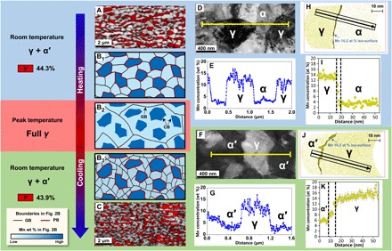
(A) EBSD image quality map with superposed phase color map of the face-centered cubic (FCC) phase (red region) of the ART-processed steel, showing the equiaxed microstructure of austenite (γ) with ferrite (α), and (C) the ultrafine dual phase microstructure of γ and martensite (α′) of the CBE-processed steel. (B) Sketch of the microstructural evolution of the steels during ultrafast heating and quenching via the CBE strategy to illustrate the role of GBs, PBs, and CBs. (D and E) TEM images with EDS analysis showing the microstructure and Mn concentration profile between γ and α of the ART-processed steel, while (F and G) is that between γ and α′ of the CBE-processed steel. Near-atomic level Mn distribution is revealed by 3D-APT, (H and I) between γ and α, and (J and K) between γ and α′.
Creating CBs by fast heating
To convert these sharp Mn discontinuities at austenite/ferrite PBs into CBs, the ART-processed steels are rapidly heated (>100°C/s) to the single-phase austenite region (800°C), followed by immediate quenching to ambient temperature. As shown in Fig. 2B, the fast heating results in the rapid elimination of all austenite/ferrite PBs and many GBs, i.e., there is a detachment between each PB and its associated chemical discontinuity (fig. S1). As a result of its sluggish diffusion, the spatial distribution of Mn is preserved, resulting in the formation of a high density of nonequilibrium CBs, as sketched in Fig. 2B2. These CBs divide the extensively coarsened austenite grains into a large number of ultrafine domains alternately enriched or depleted in Mn. Thus, in addition to GBs, the high density of CBs existing inside the austenite grains can act as a new feature to realize microstructural architecturing.
CBs acting as barriers to martensitic transformation
As a typical example of GBE, reducing the austenite grain size, e.g., by enhancing the density of austenite GBs, to block various transformations upon cooling (e.g., martensite, bainite, etc.), has proven to be an effective route to address the long-standing strength-ductility trade-off dilemma in steels (8, 11). However, because of the limited thermal stability of GBs at elevated temperatures, the austenite grain size cannot be readily reduced below 2 to 3 μm by conventional thermomechanical processing (11). Using the CBE approach described in this study, however, each austenite grain can be further divided into submicron domains by CBs, which are found to act during quenching in the same manner as GBs, providing strong barriers to block the propagation of martensitic laths, as sketched in Fig. 2B3. Yet, the underlying mechanism is different: GBs stop martensite growth because of a crystallographic discontinuity (10, 11), whereas CBs stop the martensitic growth by a local reduction in driving force due to the chemical discontinuity. As a result, the ferrite-austenite duplex microstructure in ART-processed steels is transformed into a dual-phase microstructure consisting of ultrafine equiaxed metastable austenite, distributed in a strong, ultrafine 3D martensitic network (Fig. 2C). The austenite fractions and Mn distributions of the ART- and CBE-processed samples are nearly identical (Fig. 2, D to K), indicating no pronounced Mn redistribution during the ultrafast heating and quenching.
These CBs are not preserved at room temperature, but their existence can be demonstrated by its effect on the martensite formation during cooling. To illustrate the effect of CBs on martensitic formation, correlative nano-Auger and high-resolution EBSD have been used to map the local crystallographic orientations and the Mn distribution in the same volume of the CBE-processed sample. Figure 3A shows an EBSD image quality map superimposed on an inverse pole figure map for the austenite. Several martensitic blocks are seen, separated by high angle boundaries, together with regions of metastable austenite. By a parent-grain orientation reconstruction (see Materials and Methods), it is found that martensite blocks are formed from austenite with the same orientation as the surrounding metastable austenite (Fig. 3B), i.e., they are formed from the same prior austenite grain. The corresponding nano-Auger maps of the Mn concentration (Fig. 3C) confirm the presence of a sharp CB between the martensite and austenite regions, proving that the martensite growth is effectively stopped by the CBs.
Fig. 3. Nano-Auger–EBSD and TEM analysis of the CBE-processed steel.
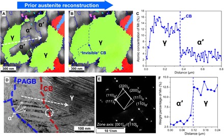
(A) Inverse pole figure map of austenite combined with image quality map of martensite. (B) Prior austenite reconstruction of (A) showing that the martensite blocks in the center share the same parent austenite orientation with the surrounding austenite. Blue and green lines in the EBSD maps correspond to high- and low-angle GBs, respectively (misorientation of ≥15° and between 5° and 15°, respectively). (C) Mn concentration profile obtained by nano-Auger line scan along the white line in (A), further confirming that the CB hinders martensitic transformation. (D) TEM bright field micrograph showing nanocrystalline martensitic laths stop at the CB. Prior austenite grain boundary (PAGB) represents prior austenite GB. (E) Corresponding selected area diffraction pattern in the marked area in (D) showing the near Nishiyama-Wassermann relationship between α′ and γ on both sides of the CBs due to having the same parent austenite. (F) Mn concentration profile obtained by TEM-EDS line scan along the white line in (D).
Figure 3 (D and E) shows TEM images of the CBE-processed steel, with a corresponding selected area diffraction image. It is directly revealed that the growth of the extremely fine martensite laths (thickness of ~15 nm) is stopped at the CBs and that they show a Nishiyama-Wassermann orientation relationship with the original austenite. The typical length of the martensite laths in the CBE-processed steel is around 130 nm, at least 10 times shorter than those in conventionally GBE-processed steels (11). In addition, the planar defect density (mainly twining) in the austenite is significantly enhanced due to plastic deformation caused by the martensitic transformation (Fig. 3D) (10).
Resulting mechanical properties
Using the CBE concept, we managed to create a unique microstructure in a low carbon, medium Mn steel. The engineering stress-strain curves in Fig. 4A show that the yield and ultimate tensile strength are substantially enhanced, with nearly no loss in both uniform and total elongation as compared with the conventional ART-processed steel. A reference sample not containing CBs (i.e., cold rolling and without ART), processed similarly to the CBE-processed sample, is very brittle and fails just after yielding (fully martensitic microstructure).
Fig. 4. Mechanical properties of the investigated steels.
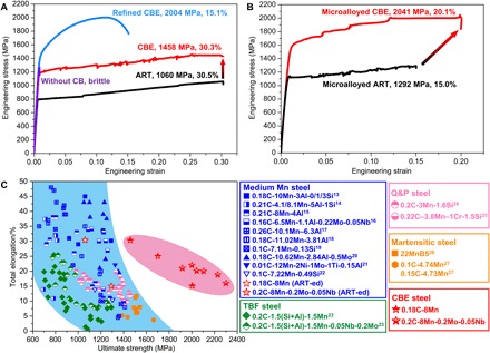
(A) Mechanical properties of the 0.18C-8Mn steel and (B) 0.2C-8Mn-0.2Mo-0.05Nb steel subjected to various thermomechanical treatments. (C) Comparison of mechanical properties of the CBE-processed steels with other low carbon advanced high-strength steels (more details in fig. S4) (13, 23–25). To allow a fair comparison, all data are from tensile tests with a gauge geometry obeying the ASTM E8/E8M standard. The stress jumps and serrations in the tensile curves are due to the Portevin-Le Chatelier (PLC) effect, which is frequently observed in medium Mn steels (36).
The yield strength of the CBE-processed sample (containing ~45 volume % γ) is comparable to that of the reference sample with a fully martensitic structure (1170 MPa versus 1250 MPa). The substantially refined martensite and the prevalence of nanotwinning inside the austenite (Fig. 3D) are direct results from the current CBE process. They constitute two important contributions to the yield strength improvement. Furthermore, the ultrafine 3D martensitic network isolates austenite in submicron domains, which strongly restrict dislocation pileups at the austenite-martensite interfaces (Fig. 5, A to D). This hinders slip propagation from austenite to martensite grains, thus a higher stress is required to initiate macroscopic yielding of the material. Therefore, we propose that the yielding of the CBE-processed steel is similar to that of a network-structured composite (12), governed more by the hard martensite frame rather than by the austenite. This micromechanical behavior serves as another contribution to the yield strength increase. The martensite will gradually start to yield at the initial stage of the percolative plastic deformation, thereby providing the high initial work hardening rate (Fig. 6A). The deformation behavior of such a submicron scaled network-reinforcement microstructure has barely received any attention in the steel community, primarily as until now, no routes to create such a structure had been identified. Our new concept provides a nearly ideal solution of maximizing the strength contribution from martensite while still retaining suitable ductility.
Fig. 5. Microstructural change of the CBE sample during deformation.
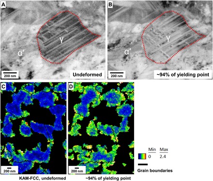
Electron channeling contrast imaging (ECCI) of the sample (A) before deformation and (B) after being stressed to ~94% of the yield point. The contrast in the lower region of the austenite grain changes after deformation, indicating that dislocations are generated in this grain and pile up at the α′-γ interface. EBSD kernel average misorientation (KAM) mappings of austenite in the sample (C) before deformation and (D) after being stressed to ~94% of the yield point. The EBSD data show an increase in local misorientation near interface regions after deformation, suggesting a higher number of geometric necessary dislocations in these areas. These results support that when the CBE sample is stressed to near-macroscopic yield point, microyielding takes place inside the nanotwined austenite. The ultrafine martensitic network isolates austenite in submicron domains, which limits dislocation pileups at austenite-martensite interfaces.
Fig. 6. Strain-induced martensitic transformation of metastable austenite and work hardening behavior in ART and CBE steels.
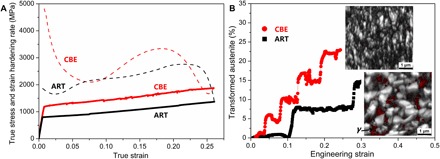
(A) Strain hardening behaviors of ART and CBE steels. (B) Kinetics of strain-induced martensitic transformation in ART and CBE steels measured by in situ magnetic induction, along with the microstructure as observed by EBSD near the fracture site, where austenite is marked in red in the EBSD maps. The step-like transformation is due to PLC bands passing through the measured volume. The transient increase and decrease in the transformed austenite fraction at the beginning of each step are artifacts caused by the PLC bands entering and leaving the finite magnetic probing area.
The other notable phenomenon is the absence of a strength-ductility trade-off (i.e., no loss of ductility). Martensite is expected to have a lower ductility compared with ferrite with regard to storage of forest dislocations during straining. However, the CBE-processed sample shows a higher overall work hardening rate as compared with ART-processed sample (Fig. 6A), which strongly suggests that there are other work hardening sources. We demonstrate that this additional work hardening derives from a higher extent of the transformation-induced plasticity (TRIP) effect. In situ magnetic induction measurements (Fig. 6B) show that the kinetics of deformation-induced martensite transformation (DIMT) in the ART-processed steel is rather slow, due to the relatively low strain partitioning ratio between ferrite and austenite (13). Hence, a significant amount of metastable austenite remains untransformed even after fracture so that the TRIP potential of the austenite is not fully used (Fig. 6B). In contrast, for the CBE-processed steel, the large hardness difference between austenite and martensite (fig. S2) enhances the strain partitioning and thus promotes DIMT. Moreover, extensive nanotwinning intersections in the austenite of the CBE-processed steel can act as preferential nucleation site for deformation-induced martensite (14), which further enhances DIMT kinetics and promotes work hardening via TRIP effects (Fig. 6, A and B).
As in the case of GBE, we can also further manipulate the “strength contribution” of the CBs in CBE. To demonstrate this, we imposed a conventional cold reduction of 70% to the ART-processed steel before the fast heating-quenching step, leading to a refined CBE steel. Cold deformation increases the density of CBs by fragmentation of the Mn-enriched/depleted domains, restricting martensite formation to even smaller domain sizes. As indicated in Fig. 4A, the ultimate tensile strength of the refined CBE steel is significantly increased to 2004 MPa, e.g., around 940 MPa higher than the reference ART-processed material. Despite an exceptional increase in strength, the refined CBE steel is still very ductile with a total elongation of 15%. In addition, it is interesting to observe that there is no apparent Portevin-Le Chatelier (PLC; serrations in the tensile curve) effect during the deformation of the refined CBE steel as compared with the CBE-processed steel. The actual formation mechanism of PLC bands in duplex medium Mn steels still remains an unsolved issue. However, from a phenomenological point of view, the grain size of retained austenite is reduced, and the overall dislocation density is significantly increased in the refined CBE sample (fig. S3, A to C). These factors can affect the strain-induced transformation of retained austenite and TRIP-related deformation responses, which may lead to the different PLC behavior of the refined CBE steel (14, 15).
To further explore the potential of CBE, we consider how the CBE approach can be applied to microalloyed medium Mn steels, where additional strengthening is provided by precipitation hardening. For this, a new medium Mn steel with a composition of 0.2C-8Mn-0.05Nb-0.2Mo (wt %) was designed, allowing both precipitation hardening and exploitation of the CBE microstructure design strategy. An excellent combination of an ultimate tensile strength of 2041 MPa and a total elongation of 20% is achieved after using the CBE approach (Fig. 4B). The micro-additions of Nb and Mo lead to the formation of nanosized carbides (fig. S3D) during ART, which further enhances the strength of the CBE steel by ~600 MPa.
The mechanical properties of medium Mn steels processed using various parameters following the CBE strategy (see details in fig. S4) are summarized in Fig. 4C. They are compared to those of existing advanced high-strength steels with similar low carbon contents. To allow a fair comparison, all reported data are from tensile tests with a gauge geometry obeying the ASTM E8/E8M standard. It is seen that the CBE-processed steels have exceptional mechanical properties and occupy a separate area in the high-strength part of the mechanical property map.
DISCUSSION
The fast detachment of chemical discontinuities from PBs creates chemical heterogeneities inside each austenite grain with sharp interfaces, i.e., CBs. Note that chemical heterogeneity has traditionally been regarded as a detrimental manufacturing effect which should be avoided or rectified, e.g., segregation during steel production requiring homogenization at very high temperatures for prolonged times to guarantee properties, which is expensive and time consuming. Some attention has been paid previously to the use of chemical heterogeneity as an effective route to improve the mechanical behavior of steels (17–19). However, in these previous studies, the importance of the sharpness of the chemical gradients between chemically heterogeneous domains was not realized and exploited. In the CBE concept, we can not only create chemical heterogeneity in the absence of a PB but can also precisely control the sharpness of the chemical gradients (i.e., CBs) by fast heating and a well-designed kinetic mismatch between the sluggish diffusion of Mn in austenite on the one hand and the rapid interface migration of preexisting austenite/ferrite PBs on the other hand. The width of the sharp chemical transition region is only slightly increased from ~4 nm (Fig. 2I), when it coexists with PBs, to ~7 nm (Fig. 2K) upon being converted to CBs. As the diffusivity of the interstitial C is several orders of magnitude faster than that of Mn, the distribution of C becomes homogenized within a very short time period as compared with Mn. Therefore, only CBs of Mn are formed in the current case.
The sharpness of the CBs plays a dominant role in determining the mechanical properties: The thickness of the CBs is experimentally found to increase to ~100 nm by use of a short isothermal holding for 1 min after fast heating to 800°C, which is in good agreement with DICTRA simulations of the spatial stability of CBs (fig. S4). As a consequence, the mechanical properties are found to be significantly deteriorated due to the tendency to form brittle ε-martensite inside thick transition regions (fig. S5). Therefore, as shown in Fig. 4C, the excellent mechanical properties of the CBE-processed steels indicate that the extension of the uncontrolled chemical heterogeneity concept to controlled CBE provides a significant advance in further enhancing the performance of steels. We envisage that CBE could allow further optimization of properties by additionally tuning both composition and processing parameters. In addition, the CBE methodology, in principle, can be applied to other alloy systems such as duplex titanium alloys, in which significant alloy elemental partitioning among the phases takes place. Also, the CBE approach seems to be a suitable microstructural design routine for application as a surface treatment method on thicker cross-sectional products, where sufficiently rapid heating and cooling throughout the bulk cannot be achieved. We believe that as technical development of fast heating methods continues, the CBE concept can have a broad application prospect.
CONCLUSION
In summary, the current study demonstrates that CBE opens up alternative routes to achieve unique microstructures other than via conventional GBE approaches, leading to ductile and strong steels without high carbon content and expensive doping elements. The CBs in this study are created at high temperatures by the mismatch between the sluggish Mn diffusion in austenite and fast migration of austenite/ferrite PBs. The extensive CBs can then restrain the martensitic transformation to submicron regions during subsequent quenching, resulting in an extremely fine martensite + austenite microstructure. The hard martensite network delays yielding, and the enhanced TRIP effect guaranties good ductility. The CBE method can be extended to other metallic systems and possibly be used as a surface treatment.
MATERIALS AND METHODS
Materials preparation
The chemical composition (table S1) of the two medium Mn steels presented in this work was measured by high-frequency infrared absorption spectrometer and wet-chemical analysis. The ingot was cast in a vacuum induction melting furnace and forged into several rectangular billets (length, 200 mm; width, 200 mm; thickness, 60 mm). After homogenization treatment at 1200°C for 48 hours under Ar atmosphere protection, the billet was hot-rolled above 1000°C and then cold-rolled into sheets with a thickness of 1.6 mm.
Heat treatment
For the ART and microalloyed ART steel samples, the cold-rolled sheets were intercritically annealed at 600°C for 2 hours, followed by water-quenching. To fabricate the CBE and microalloyed CBE steel samples, the ART and microalloyed ART samples were heated to 800°C at a rate of ~100°C/s and immediately water-quenched, followed by tempering at 400°C for 1 min. For the refined CBE steel sample, the ART steel was additionally cold-rolled to a total reduction of 70%, followed by the same fast heating, quenching, and tempering process as that of the CBE and microalloyed CBE steel samples. Detailed heat treatment parameters of other efforts to tweak the mechanical properties of steels using the CBE methodology are shown in the caption of fig. S4.
Microstructure characterization
Multiple methods were used to analyze the microstructure characteristics of the investigated steels. Nano-Auger–EBSD measurements were performed using a PHI-710 scanning auger nanoprobe. The detailed procedure for the nano-Auger–EBSD measurements can be found elsewhere (20). The spatial resolution of nano-Auger scanning under the operative voltage of 20 kV and a current of 10 nA is 18 nm. The prior austenite reconstruction was carried out with help of the APRGE software, using the theoretical crystallographic structure formed by martensite variants (21, 22). TEM observations were performed in a JEOL JEM-2100F instrument at 200 kV. The atom probe experiments were carried out in a Cameca LEAP 5000 XR instrument. Needle-shaped APT specimens were prepared by means of a site-specific lift-out procedure using a FEI Helios G4 CX focused ion beam (FIB)/scanning electron microscope (SEM). The atom probe analyses were carried out in the voltage pulsing mode at a specimen temperature of 75 K with a target evaporation rate of 5 ions per 1000 pulses, a pulse fraction of 20%, and a pulse rate of 200 kHz. The APT data were reconstructed and analyzed using the commercial IVAS 3.6.14 software.
Mechanical property tests
Flat dog-bone–shaped tensile specimens according to the ASTM E8/E8M standard were machined along the rolling direction from the heat-treated sheets with a gauge length of 25 mm and a gauge width of 6 mm. The samples were tested at an initial strain rate of 10−3/s in an Instron machine at ambient temperature. Three samples for each material were tested to confirm reproducibility. The DIMT during tensile testing was analyzed by an in situ magnetic induction method implemented by a Feritscope (Fischer, FMP 30). It was calibrated in advance using standard samples which have different combinations of retained austenite (0 to 60%), ferrite, and deformation-induced α′-martensite. A linear relationship with a Pearson correlation coefficient of 0.994 exists between the magnetic induction results and the standard values. The probe of the Feritscope was attached to the center of each tensile sample during testing, covering a circular surface area of 2 mm in diameter for the analysis. Nanoindentation hardness values were measured on electropolished surfaces by the Keysight Nano indenter G200 with a Berkovich indenter of a half angle of 65.3°. A maximum load of 0.5 mN was applied, and the load was maintained for 30 s before the final unloading to allow the surface relaxation. An ex situ tensile testing combined with electron channeling contrast imaging (ECCI) and EBSD (a JEOL JSM-6500F SEM instrument for EBSD and a Zeiss-Merlin SEM instrument for ECCI) was carried out to investigate the microstructural evolution of the CBE sample during the yielding stage.
Supplementary Material
Acknowledgments
We thank C. Cayron at École Polytechnique Fédérale de Lausanne for providing the ARPGE software to reconstruct prior austenite; H.K. Dong, J. Zhang, W.Q. Gao, and B.N. Zhang at Tsinghua University for help with sample characterizations. T.L. would like to acknowledge Zentrum für Grenzflächendominierte Höchstleistungswerkstoffe (ZGH) at Ruhr University Bochum for the access of infrastructure (FEI Helios G4 CX FIB/SEM and Cameca LEAP 5000 XR). B.S. gratefully acknowledges the research fellowship provided by the Alexander von Humboldt Foundation. Funding: H.C. acknowledges financial support from the National Natural Science Foundation of China (grants 51922054, U1860109, U1808208, and 51501099), Beijing Natural Science Foundation (grant 2182024), National Key R&D program of China (grant 2016YFB0300104), and National Young 1000-Talents Program (grant D1101073). R.D. acknowledges financial support from China Postdoctoral Science Foundation (grants 2017M610082 and 2018T110096). C.Z. and Z.Y. acknowledge financial support from the National Natural Science Foundation of China (grants 51771097 and U1764252). A.G. acknowledges financial support from the National Natural Science Foundation of China (grant 51671113). Author contributions: H.C. conceived the project. H.C. and R.D. designed the research. R.D., Y.Y., J.H., G.L., and X.W. carried out the alloy preparation and microstructural characterization experiments. B.S. performed the in situ magnetic induction tests and the ex situ ECCI+EBSD experiments. T.L., G.M., and T.F. conducted the 3D-APT experiments. H.C., R.D., D.P., D.R., C.Z., S.v.d.Z., A.G., G.M., T.F., Z.D., and Z.Y. analyzed the data. All authors discussed the results and contributed the manuscript. Competing interests: The authors declare that they have no competing interests. Data and materials availability: All data needed to evaluate the conclusions in the paper are present in the paper and/or the Supplementary Materials. Additional data related to this paper may be requested from the authors.
SUPPLEMENTARY MATERIALS
Supplementary material for this article is available at http://advances.sciencemag.org/cgi/content/full/6/13/eaay1430/DC1
Fig. S1. Dilatometry study and inverse pole figure maps of austenite.
Fig. S2. Nanohardness of each phase in ART and CBE steels.
Fig. S3. Microstructures of refined CBE steel and microalloyed CBE steel.
Fig. S4. DICTRA simulation of the spatial stability of a CB inside austenite at 800°C.
Fig. S5. Extended mechanical properties.
Table S1. Chemical composition of the studied alloys in weight %.
Reference (37)
REFERENCES AND NOTES
- 1.Decker R. F., Eash J. T., Goldman A. J., 18% Nickel maraging steel. Trans. ASM 55, 58–76 (1962). [Google Scholar]
- 2.Morris J. W., Jr., Maraging steels: Making steel strong and cheap. Nat. Mater. 16, 787–789 (2017). [DOI] [PubMed] [Google Scholar]
- 3.Jiang S., Wang H., Wu Y., Liu X., Chen H., Yao M., Gault B., Ponge D., Raabe D., Hirata A., Chen M., Wang Y., Lu Z., Ultrastrong steel via minimal lattice misfit and high-density nanoprecipitation. Nature 544, 460–464 (2017). [DOI] [PubMed] [Google Scholar]
- 4.He B. B., Hu B., Yen H. W., Cheng G. J., Wang Z. K., Luo H. W., Huang M. X., High dislocation density–induced large ductility in deformed and partitioned steels. Science 357, 1029–1032 (2017). [DOI] [PubMed] [Google Scholar]
- 5.Watanabe T., Grain boundary engineering: Historical perspective and future prospects. J. Mater. Sci. 46, 4095–4115 (2011). [Google Scholar]
- 6.Randle V., Owen G., Mechanisms of grain boundary engineering. Acta Mater. 54, 1777–1783 (2006). [Google Scholar]
- 7.Lu K., Stabilizing nanostructures in metals using grain and twin boundary architectures. Nat. Rev. Mater. 1, 16019 (2016). [Google Scholar]
- 8.Offerman S. E., van Dijk N. H., Sietsma J., Grigull S., Lauridsen E. M., Margulies L., Poulsen H. F., Rekveldt M. T., van der Zwaag S., Grain nucleation and growth during phase transformations. Science 298, 1003–1005 (2002). [DOI] [PubMed] [Google Scholar]
- 9.Lee Y.-K., Han J., Current opinion in medium manganese steel. Mater. Sci. Technol. 31, 843–856 (2014). [Google Scholar]
- 10.Miyamoto G., Shibata A., Maki T., Furuhara T., Precise measurement of strain accommodation in austenite matrix surrounding martensite in ferrous alloys by electron backscatter diffraction analysis. Acta Mater. 57, 1120–1131 (2009). [Google Scholar]
- 11.Morito S., Saito H., Ogawa T., Furuhara T., Maki T., Effect of austenite grain size on the morphology and crystallography of lath martensite in low carbon steels. ISIJ Int. 45, 91–94 (2005). [Google Scholar]
- 12.Huang L. J., Geng L., Peng H.-X., Microstructurally inhomogeneous composites: Is a homogeneous reinforcement distribution optimal? Prog. Mater. Sci. 71, 93–168 (2015). [Google Scholar]
- 13.Sun B., Fazeli F., Scott C., Brodusch N., Gauvin R., Yue S., The influence of silicon additions on the deformation behavior of austenite-ferrite duplex medium manganese steels. Acta Mater. 148, 249–262 (2018). [Google Scholar]
- 14.Nakada N., Ito H., Matsuoka Y., Tsuchiyama T., Takaki S., Deformation-induced martensitic transformation behavior in cold-rolled and cold-drawn type 316 stainless steels. Acta Mater. 58, 895–903 (2010). [Google Scholar]
- 15.Sun B., Fazeli F., Scott C., Guo B., Aranas C. Jr., Chu X., Jahazi M., Yue S., Microstructural characteristics and tensile behavior of medium manganese steels with different manganese additions. Mater. Sci. Eng. A 729, 496–507 (2018). [Google Scholar]
- 16.Sun B., Vanderesse N., Fazeli F., Scott C., Chen J., Bocher P., Jahazi M., Yue S., Discontinuous strain-induced martensite transformation related to the Portevin-Le Chatelier effect in a medium manganese steel. Scr. Mater. 133, 9–13 (2017). [Google Scholar]
- 17.Heo Y.-U., Suh D.-W., Lee H.-C., Fabrication of an ultrafine-grained structure by a compositional pinning technique. Acta Mater. 77, 236–247 (2014). [Google Scholar]
- 18.Sun W. W., Wu Y. X., Yang S. C., Hutchinson C. R., Advanced high strength steel (AHSS) development through chemical patterning of austenite. Scr. Mater. 146, 60–63 (2018). [Google Scholar]
- 19.Belde M., Springer H., Inden G., Raabe D., Multiphase microstructures via confined precipitation and dissolution of vessel phases: Example of austenite in martensitic steel. Acta Mater. 86, 1–14 (2015). [Google Scholar]
- 20.Ding R., Dai Z. B., Huang M. X., Yang Z. G., Zhang C., Chen H., Effect of pre-existed austenite on austenite reversion and mechanical behavior of an Fe-0.2C-8Mn-2Al medium Mn steel. Acta Mater. 147, 59–69 (2018). [Google Scholar]
- 21.Miyamoto G., Iwata N., Takayama N., Furuhara T., Mapping the parent austenite orientation reconstructed from the orientation of martensite by EBSD and its application to ausformed martensite. Acta Mater. 58, 6393–6403 (2010). [Google Scholar]
- 22.Cayron C., ARPGE: A computer program to automatically reconstruct the parent grains from electron backscatter diffraction data. J. Appl. Cryst. 40, 1183–1188 (2007). [DOI] [PMC free article] [PubMed] [Google Scholar]
- 23.Park S.-J., Heo Y.-U., Choi Y. H., Lee K., Han H. N., Suh D.-W., Effect of second phase on the deformation and fracture behavior of multiphase low-density steels. JOM 66, 1837–1844 (2014). [Google Scholar]
- 24.Cai Z., Ding H., Ying Z., Misra R. D. K., Microstructural evolution and deformation behavior of a hot-rolled and heat treated Fe-8Mn-4Al-0.2C steel. J. Mater. Eng. Perform. 23, 1131–1137 (2014). [Google Scholar]
- 25.Cai M.-H., Huang H.-S., Pan H.-J., Sun S.-H., Ding H., Hodgson P., Microstructure and tensile properties of a Nb–Mo microalloyed 6.5Mn alloy processed by intercritical annealing and quenching and partitioning. Acta Metall. Sin. 30, 665–674 (2017). [Google Scholar]
- 26.Lee C.-Y., Jeong J., Han J., Lee S.-J., Lee S., Lee Y.-K., Coupled strengthening in a medium manganese lightweight steel with an inhomogeneously grained structure of austenite. Acta Mater. 84, 1–8 (2015). [Google Scholar]
- 27.Cai Z. H., Ding H., Xue X., Xin Q. B., Microstructural evolution and mechanical properties of hot-rolled 11% manganese TRIP steel. Mater. Sci. Eng. A 560, 388–395 (2013). [Google Scholar]
- 28.Gibbs P. J., De Moor E., Merwin M. J., Clausen B., Speer J. G., Matlock D. K., Austenite stability effects on tensile behavior of manganese-enriched-austenite transformation-induced plasticity steel. Metall. Mater. Trans. A 42, 3691–3702 (2011). [Google Scholar]
- 29.Marquis E. A., Choi P. P., Danoix F., Kruska K., Lozano-Perez S., Ponge D., Raabe D., Williams C. A., New insights into the atomic-scale structures and behavior of steels. Micros. Today 20, 44–48 (2012). [Google Scholar]
- 30.Kwiatkowski da Silva A., Inden G., Kumar A., Ponge D., Gault B., Raabe D., Competition between formation of carbides and reversed austenite during tempering of a medium-manganese steel studied by thermodynamic-kinetic simulations and atom probe tomography. Acta Mater. 147, 165–175 (2018). [Google Scholar]
- 31.Sugimoto K.-i., Murata M., Muramats T., Mukai Y., Formability of C–Si–Mn–Al–Nb–Mo ultra high-strength TRIP-aided sheet steels. ISIJ Int. 47, 1357–1362 (2007). [Google Scholar]
- 32.De Moor E., Speer J. G., Matlock D. K., Kwak J. H., Lee S. B., Effect of carbon and manganese on the quenching and partitioning response of CMnSi steels. ISIJ Int. 51, 137–144 (2011). [Google Scholar]
- 33.Kim J. H., Seo E. J., Kwon M.-H., Kang S., De Cooman B. C., Effect of quenching temperature on stretch flangeability of a medium Mn steel processed by quenching and partitioning. Mater. Sci. Eng. A 729, 276–284 (2018). [Google Scholar]
- 34.Hanlon D. N., van Bohemen S. M. C., Celotto S., Critical Assessment 10: Tensile elongation of strong automotive steels as function of testpiece geometry. Mater. Sci. Technol. 31, 385–388 (2015). [Google Scholar]
- 35.Arlazarov A., Bouaziz O., Hazotte A., Gouné M., Allain S., Characterization and modeling of manganese effect on strength and strain hardening of martensitic carbon steels. ISIJ Int. 53, 1076–1080 (2013). [Google Scholar]
- 36.Wang X. G., Wang L., Huang M. X., Kinematic and thermal characteristics of Luders and Portevin-Le Châtelier bands in a medium Mn transformation-induced plasticity steel. Acta Mater. 124, 17–29 (2017). [Google Scholar]
- 37.Zhu J., Ding R., He J., Yang Z., Zhang C., Chen H., A cyclic austenite reversion treatment for stabilizing austenite in the medium manganese steels. Scr. Mater. 136, 6–10 (2017). [Google Scholar]
Associated Data
This section collects any data citations, data availability statements, or supplementary materials included in this article.
Supplementary Materials
Supplementary material for this article is available at http://advances.sciencemag.org/cgi/content/full/6/13/eaay1430/DC1
Fig. S1. Dilatometry study and inverse pole figure maps of austenite.
Fig. S2. Nanohardness of each phase in ART and CBE steels.
Fig. S3. Microstructures of refined CBE steel and microalloyed CBE steel.
Fig. S4. DICTRA simulation of the spatial stability of a CB inside austenite at 800°C.
Fig. S5. Extended mechanical properties.
Table S1. Chemical composition of the studied alloys in weight %.
Reference (37)


