Abstract
Pelvic organ prolapse (POP) meshes are exposed to predominately tensile loading conditions in vivo that can lead to pore collapse by 70–90%, decreasing overall porosity and providing a plausible mechanism for the contraction/shrinkage of mesh observed following implantation. To prevent pore collapse, we proposed to design synthetic meshes with a macrostructure that results in auxetic behavior, the pores expand laterally, instead of contracting when loaded. Such behavior can be achieved with a range of auxetic structures/geometries. This study utilized finite element analysis (FEA) to assess the behavior of mesh models with eight auxetic pore geometries subjected to uniaxial loading to evaluate their potential to allow for pore expansion while simultaneously providing resistance to tensile loading. Overall, substituting auxetic geometries for standard pore geometries yielded more pore expansion, but often at the expense of increased model elongation, with two of the eight auxetics not able to maintain pore expansion at higher levels of tension. Meshes with stable pore geometries that remain open with loading will afford the ingrowth of host tissue into the pores and improved integration of the mesh. Given the demonstrated ability of auxetic geometries to allow for pore size maintenance (and pore expansion), auxetically designed meshes have the potential to significantly impact surgical outcomes and decrease the likelihood of major mesh-related complications.
Keywords: bowtie mesh, pelvic organ prolapse, Poisson's ratio, polypropylene, uniaxial/tensile loading
1. Introduction
Synthetic meshes are commonly used in the repair of pelvic organ prolapse (POP), one of the most prevalent pelvic floor disorders characterized by the descent of the pelvic organs into the vaginal canal. Of the 300,000 surgeries performed to repair POP in 2010, one-third involved the use of mesh. In spite of a good anatomic success rate of approximately 82%, mesh usage has been hampered by complications with mesh exposure through the vaginal epithelium and pain being the two most commonly reported [1,2]. Recent research suggests that collapse of the mesh pores may be contributing to the pathogenesis of POP mesh complications [3,4].
The majority of current POP meshes are simply hernia meshes remarketed for POP repair. Additionally, these devices are manufactured from polypropylene and typically have large pores (i.e., >1 mm) with a porosity (defined as the amount of void space in a mesh relative to the mesh area) that is greater than 55%. However, these characteristics describe the mesh in the unloaded state and prior to implantation. In vivo, the dominating forces applied to POP meshes are tensile [3]. Unlike hernia meshes, in which tension is applied circumferentially, tension in POP mesh applications primarily occurs unidirectionally either along the longitudinal axis of the mesh (sacrocolpopexy) or along mesh arms (transvaginal mesh procedures). Meshes that are not constrained or tensioned uniformly around their perimeter change shape, and this change largely results from a reorientation and modification in the structural geometry of the mesh pores [5,6]. In many cases, the application of tension well within the physiologic range causes the pores of most POP meshes to collapse, resulting in pore diameters that are less than 1 mm—a critical size for tissue ingrowth [3,7].
Meshes with small pores and low porosity are associated with increased inflammation and fibrosis and yield poor tissue integration with decreased collagen deposition relative to meshes with large pores and high porosity [8–11]. Additionally, smaller pores increase the risk of bridging fibrosis (overlapping of the foreign body response to neighboring fibers), a process that can lead to encapsulation and pain [10,11]. Clinically, mesh contraction (i.e., pores collapsing) is associated with vaginal pain, and interestingly, problematic areas for patients experiencing mesh complications are often located in areas where the pores of a mesh have collapsed after tensioning and/or loading [4]. Collectively, these findings strongly suggest that controlling the response of pores to loading is a critical design consideration in the development of POP meshes that has the potential to lead to better host integration and fewer complications.
With a long-term goal of overcoming the problem of pore collapse and mesh contraction, we proposed to design synthetic meshes with auxetic pore geometries. The term auxetic refers to materials that have a negative Poisson's ratio and structures that demonstrate behaviors such as lateral expansion when placed in tension. This type of behavior is counterintuitive given that most materials contract or narrow in the transverse direction when stretched longitudinally, i.e., they have a positive Poisson's ratio. To date, auxetic geometries have been utilized to manufacture annuloplasty prostheses for cardiac valve repair surgery, artificial intervertebral disks, cushion pads, and knee prosthetics [12,13]. However, beyond these applications, there has been limited use of auxetic geometries within the biomedical field. The development of a mesh with pores designed to open in response to tension as opposed to contracting has the potential to be highly beneficial in regards to the development of meshes for POP repair.
The objective of this study was to assess the behavior of auxetic pore geometries with tensile loading and to evaluate their potential to provide resistance to tensile loads while simultaneously undergoing pore expansion. To minimize cost, time, and the introduction of additional variables resulting from manufacturing and mechanical testing of each design, this investigation utilized a standard engineering workflow whereby finite element analysis (FEA) was used to provide an objective first investigation to identify auxetic geometries that should be explored further as potential pore designs for POP meshes intended for sacrocolpopexy. Tension is primarily applied along the longitudinal axis of the mesh when implanted via a sacrocolpopexy (Fig. 1). The purpose of the mesh in a sacrocolpopexy is to reinforce the vaginal walls, stabilize the apex (superior) of the vagina, and to resist the motion of the distal vagina resulting from an increase in abdominal pressure. From a gross mechanical perspective, mesh function for a sacrocolpopexy is in many ways analogous to a tether. Thus, eight computational models of meshes with auxetic pore geometries (referred to as auxetic models) were constructed and subjected to simulated uniaxial tensile tests via three-dimensional quasi-static, large deformation finite element analysis. For comparison, computational models of meshes with standard pore geometries (i.e., pore shapes that are commonly used for commercial synthetic meshes) were also created and exposed to the same simulated boundary conditions as the computational models with auxetic pores. These models are referred to as standard models. Quantitative measurements of the minimal pore diameter, porosity, effective porosity, effective pore area, and overall expansion (or contraction) of the models' width, via calculation of the relative lateral contraction, were used to characterize the deformation of the pore geometries and models overall.
Fig. 1.
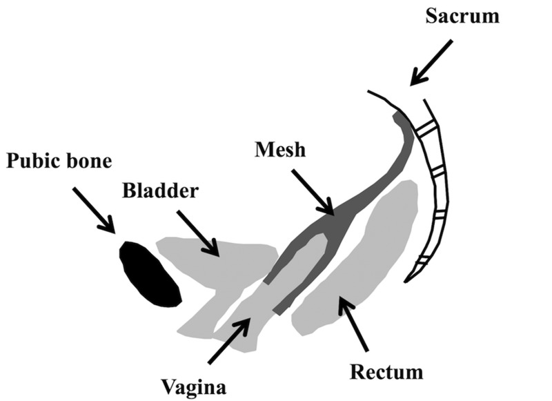
Schematic of a sacrocolpopexy in which the mesh is attached to the anterior and posterior walls of the vagina and fixed to the sacrum. In vivo intra-abdominal pressure exerts a downward force on the pelvic organs. This results in a tensile force along the longitudinal axis of the mesh.
2. Materials and Methods
2.1. Design of Models Using Computer-Aided Design.
Eight models with auxetic pore geometries and three models with standard pore geometries were generated using the computer-aided design (CAD) software, solidworks 2013 ×64 Edition (Dassault Systèmes SOLIDWORKS Corporation, Waltham, MA). The pore geometries for the auxetic models included (1) bowtie (B), (2) spiral (S), (3) triangle (T), (4) square chiral(a) (SCa), (5) chiral hexagon (CH), (6) square chiral(b) (SCb), (7) hexagon(b) (Hb), and (8) square grid (SG) (Fig. 2). These geometries were chosen as they were deemed to be without obvious limitations that would negatively impact performance or manufacturability by authors of this paper with significant mesh expertise (Pamela Moalli and Steven Abramowitch).
Fig. 2.
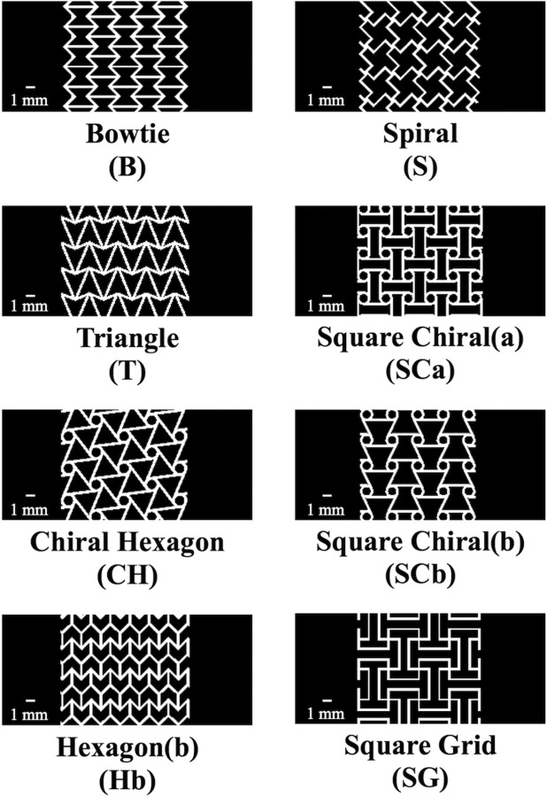
Orthographic frontal plain views of three-dimensional auxetic CAD models with eight different auxetic pore geometries. Note the models pictured represent only a portion of the total length of the CAD models utilized in the FEA.
Currently, the majority of commercially available POP meshes have pores that are either square, diamond, or hexagon shaped; therefore, these three shapes were used to construct the standard CAD models in this study. Specifically, the standard CAD models with square- and diamond-shaped pores were simplified geometries modeled after Restorelle (Coloplast, Minneapolis, MN) POP mesh, and the CAD model with hexagon-shaped pores was a simplified geometry modeled after Gynemesh PS (Ethicon, Somerville, NJ) POP mesh. Calipers were used to measure the fiber width (distance between two fibers), thickness, and the pore size of the commercial products. These dimensions were ultimately used to guide the development of the standard models which included (1) square (SQ), (2) diamond (D), and (3) hexagon(a) (Ha) (Fig. 3).
Fig. 3.
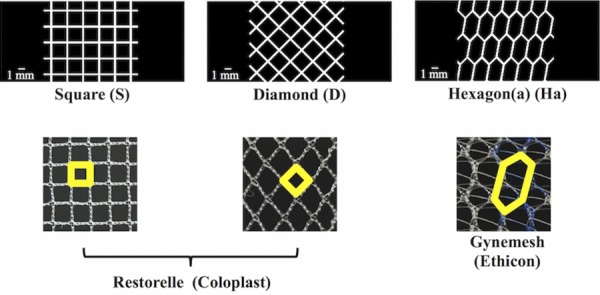
Standard CAD models (top images) were created with square, diamond, and hexagon shaped pores, which are commonly used pore shapes for commercial synthetic meshes (bottom images). Note, the outlined shapes (in bold) in the commercial images represent the geometry that was used to create the respective CAD model. Actual images of mesh (bottom images) are 10 mm × 10 mm.
Additionally, to create a realistic model with auxetic pore geometries, the dimensions (i.e., fiber width, thickness, and pore size) of the auxetic model pores were also modeled after Restorelle. The latter was chosen as the “model mesh” given the relative simplicity of the pore geometry (square pore geometry) and the ease of measuring the dimensions of these pores. However, it is important to note that the pore size of the auxetic pore geometries did not exactly match those of Restorelle due to the design/complexity of these geometries.
The pores of each model were designed with specific considerations. First, the width of the fibers equaled 0.30 mm, and the minimal pore diameter was at least 1 mm. The latter was the maximum pore size that could be achieved given the fiber width, geometry of the pore, and the requirement that the volume of material was consistent from model to model. Indeed, the majority of the models had pore dimensions that were greater than 1 mm. It should also be noted that models containing angles less than 90 deg would have small regions of the pore where two fibers would be closer than 1 mm (i.e., intersections of model fibers forming corners). To balance our interest in maximizing these spaces without compromising the auxetic behavior of any specific geometry, the smallest allowable angle within a pore was restricted to 45 deg. For designs containing circles, the diameter of the circles was equal to 1 mm.
All models had an overall length of 84.75±4.80 mm and average width of 14.79±0.82 mm resulting in an aspect ratio of at least 5. Additionally, the average volume of all models was 91.54±0.66 mm3. There was a slight variation between designs on these values, because the shape of individual pores would create inconsistencies when boundary conditions were applied to the model that would result in numerical instabilities in the simulations and biased comparisons between models. Thus, we aimed to keep these values as close as possible between designs.
2.2. Computational Analysis.
Standard and auxetic CAD models were discretized and refined using Autodesk Simulation Mechanical (Autodesk, Inc., San Rafael, CA) and Gmsh (V2.11.0), respectively. Discretized finite element models consisted of a combination of tetrahedral, pentahedral, and hexahedral elements ranging from 178,944 to 705,088 total elements per model. The Neo-Hookean material was defined for all models. Although the actual magnitude of the elongations achieved for an applied force was not as relevant as the relative elongations between mesh designs in this study, we nevertheless wanted to choose material parameters that resulted in elongations that were consistent with current mesh products. Thus, the material parameters used for all models were obtained via an inverse optimization analysis in which the uniaxial load-elongation data of Restorelle was fit to a computational simulation of Restorelle, which had the same dimensions as the physical mesh tested. Based on this optimization, it was determined that the Neo-Hookean material with a Young's Modulus of 52.98 MPa and Poisson's ratio of 0.41 could accurately describe the nonlinear load-elongation behavior of Restorelle (Fig. 4). Thus, these material parameters were utilized for all models.
Fig. 4.
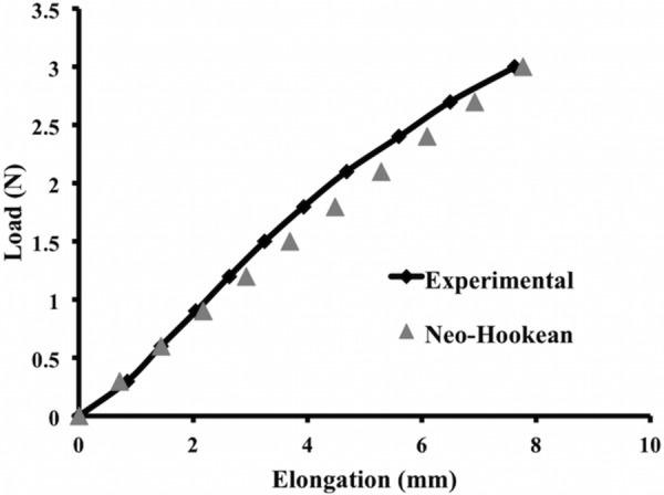
Finite element simulation of the square pore model with a Neo-Hookean material (Neo-Hookean, triangle) was able to accurately capture the ex vivo, nonlinear load-elongation behavior of Restorelle uniaxially loaded to 3 N (experimental, diamond)
Simulated uniaxial tensile tests were performed using FEBio Software Suite (University of Utah, MRL). Specifically, a rigid body was fixed to the top edge of each model allowing the rigid body to drive the displacement (Fig. 5). The rigid body was only allowed to move vertically. This allowed for the top edge of each model to be limited to only vertical displacement resulting from the application of a 3 N vertical load to the rigid body. The bottom edge of each model was fixed in translation and rotation. All deformation was constrained to be in the frontal plane of the model. The resulting deformed solution for all discretized models was obtained and postprocessed to quantify the following parameters: relative elongation, minimal pore diameter, effective pore area (area of the pores with diameters that are greater than 1 mm) [14], porosity, effective porosity (percent of void space from pores with minimal diameters that are greater than 1 mm) [14], and relative lateral contraction (analogous to the Poisson's ratio for a continuous material). Three Newtons represents the minimal amount of force that a mesh must be able to withstand based on our estimates of the surface area of the anterior vagina using magnetic resonance imaging measurements and estimates of the intra-abdominal pressure reported with sitting and standing [15–19].
Fig. 5.
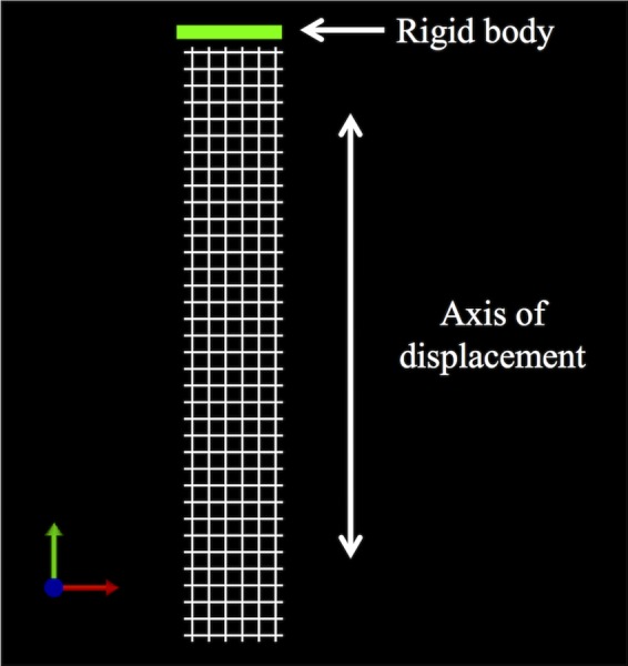
To simulate a uniaxial tensile test, the bottom edge of the models was fixed in translation and rotation, while the top edge was fixed to a rigid body
2.3. Quantification of Parameters.
Relative elongation was calculated by dividing the amount that the model elongated in response to 3 N by the initial length of the model. To quantify the minimal pore width, effective pore area, porosity, and effective porosity, a custom Mathematica V10 (Wolfram, Champaign, IL) script was utilized. These parameters were calculated for the pores within a 30 mm × 12 mm section of the mid-region of the models. The previously mentioned dimensions were chosen as they captured the repeating geometry of the pores. Additionally, focusing on those pores within the midregion of the model minimized the influence of edge effects on pore deformation. A similar method was used by Barone et al. [3]. Briefly, screenshots of the midregion of the models in the undeformed (0 N) and deformed (3 N) states were taken and imported into Mathematica. Images were then binarized and an edge detection algorithm was used to identify the fibers of the model (black pixels) and the pores (white pixels). Unlike the previous parameters, the relative lateral contraction was calculated for the models using images of the entire model (i.e., lateral edge to lateral edge). The undeformed (0 N) and deformed model images (assessed at loads of 0.6 N, 1.5 N, 2.4 N, and 3 N) were imported into a custom mathematica V10 (Wolfram, Champaign, IL) script, and the pores were identified using algorithms as described previously. Next, the center of mass (i.e., the centroid) was located for each pore, and the coordinate position of these centroids, in the un-deformed and deformed states, was exported. These positions were then used to calculate the relative lateral contraction as follows: relative lateral contraction = −(relative elongationtransverse/relative elongationlongitudinal). This parameter is representative of the degree of contraction with a positive value indicating contraction (i.e., pore collapse—typical of most materials and structures) and a negative value indicating expansion (i.e., pores remaining open/enlarging), consistent with the definition of Poisson's ratio for continuous materials.
2.4. Model Assessment Criteria.
The following four criteria were used to define what would be clinically considered to be a positive mesh response to uniaxial loading in vivo.
-
(1)
The pores can expand but the overall geometry of the pore should not be dramatically reoriented (e.g., a significant degree of rotation) in response to loading. It is believed that significant motion between the mesh and the host can negatively impact the host response to an implant, and this phenomenon has been demonstrated for percutaneous implants at the skin–device interface and for dental implants at the implant–bone interface [20,21].
-
(2)
The minimal pore diameter should be at least 1 mm, and the effective pore area as well as the porosity and effective porosity should be maintained following the application of load. In both the abdominal hernia and urogynecology literature, large pore, high porosity meshes yield better tissue integration with increased collagen deposition between the pores and decreased inflammation and fibrosis relative to meshes with small pores and low porosity [8–11]. For polypropylene meshes, 1 mm is identified as the optimal minimal pore diameter needed to allow for tissue ingrowth and to prevent bridging fibrosis [10].
-
(3)
A negative relative lateral contraction will signify mesh expansion, which is considered to be a beneficial response to loading for POP meshes. Contraction of POP meshes is associated clinically with vaginal pain, dyspareunia (pain with sexual intercourse), and tenderness upon palpation of the contracted portion of the mesh [4]. Additionally, when pores contract, the chances of bridging fibrosis increases [11]. It is therefore important that the mesh width overall, and hence the pores, are maintained or expand with loading.
-
(4)
Overall the amount of mesh elongation should be minimal to provide maximal stiffness of the mesh (i.e., reduce the risk of recurrence) with a minimal amount of material. In other words, the mesh should be as stiff as possible using the least amount of material. This is complicated by the fact that the structural stiffness of the overall mesh results from the interconnections and orientations of fibers that provide specific pore geometries, the stiffness of the material that composes those fibers (e.g., polypropylene), and the amount of that material (heavy versus light weight). Clinically, lightweight meshes have been shown to be more favorable relative to heavyweight meshes [10,22–25]. Thus, if a mesh design undergoes greater elongation relative to another design, more material (heavier weight) would be required to make them equal. Alternatively, a stiffer material could also be substituted, potentially at the risk of causing a significant stiffness mismatch between the mesh and the vagina. In this study, both the amount of material and stiffness of the material were held consistent between models so that the impact of pore geometry on relative elongation of the mesh could be assessed. This was accomplished by assigning the same constitutive model and same model parameters for each simulation and ensuring that the dimensions and volume of material used for each model was consistent across all model designs.
3. Results
3.1. Convergence Testing.
Using the boundary conditions described previously, model convergence (specifically convergence of model elongation, minimal pore diameter, and pore length) was performed for all 11 model designs using the h-refinement method. Models were considered to achieve convergence when an increase in the number of elements resulted in a less than 5% difference in the three parameters. In this study, three to four levels of refinement were utilized using a combination of tetrahedral, pentahedral, and hexahedral elements ranging from a total of 178,944 to 705,088 elements across model designs (Table 1). The results reported are for simulations in which the model elongation, minimal pore diameter, and pore length all converged within 5%. See Supplemental Figs. 1–3 for graphs of the convergence results, which are available under “Supplemental Data” tab for this paper on the ASME Digital Collection.
Table 1.
Composition of finite element models in terms of element. Numbers represent the amount of elements in each category listed in the heading.
| Tetrahedral elements | Pentahedral elements | Hexahedral elements | Total number of elements | |
|---|---|---|---|---|
| Square | 0 | 0 | 178,944 | 178,944 |
| Diamond | 0 | 0 | 228,480 | 228,480 |
| Hexagon(a) | 21,056 | 39,744 | 199,616 | 260,416 |
| Bowtie | 258,432 | 181,184 | 265,472 | 705,088 |
| Spiral | 0 | 0 | 224,768 | 224,768 |
| Triangle | 218,240 | 105,152 | 300,224 | 623,616 |
| Square chiral(a) | 212,800 | 177024 | 286,656 | 676,480 |
| Chiral hexagon | 167,296 | 204,352 | 242,944 | 614,592 |
| Square chiral(b) | 63,680 | 74,752 | 206,656 | 345,088 |
| Hexagon(b) | 162,432 | 167,872 | 314,880 | 645,184 |
| Square grid | 20,800 | 17,472 | 325,376 | 363,648 |
3.2. Computational Results.
The pore and overall model deformation of the CAD models with three standard and eight auxetic pores in response to 3 N of force was assessed via simulated uniaxial tensile tests. For the standard models, only the pores of the square model remained opened, whereas the pores of the diamond and hexagon(a) models contracted (Fig. 6). For the auxetic models, pore expansion was visibly apparent for four of the eight models: the bowtie, spiral, hexagon(b), and square grid models (Fig. 7). The triangles and the circles within the remaining four auxetic models (triangle, chiral hexagon, square chiral(a), and square chiral(b)), all contracted (Fig. 8). Overall, the pores of the square grid model experienced the most dramatic change in pore shape, changing from an initial collection of rectangles to large squares (Fig. 7). Upon qualitative assessment of the models, expansion of the bowtie, square chiral(a), and square grid models was visibly apparent unlike the diamond and hexagon(a) models, which contracted. The subtle changes in the deformation of all other models made it difficult to qualitatively determine whether these models expanded or contracted in response to 3 N. However, assessing the overall elongation of each model, it was clear that the pore geometry impacted how much the model elongated. Specifically, the square and hexagon(a) models deformed the least with relative elongations of 9.3% and 16.2%, respectively, while the square grid model deformed the most, elongating 112.1% more than its initial length.
Fig. 6.
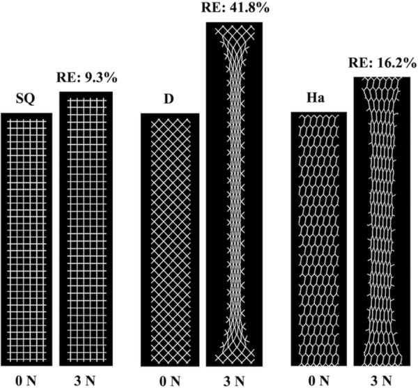
FEA results at 0 N and 3 N for the standard models. The pores of the square model (SQ) remained relatively open, whereas the pores of the diamond (D) and hexagon(a) (Ha) models collapsed resulting in model contraction. RE = relative elongation.
Fig. 7.
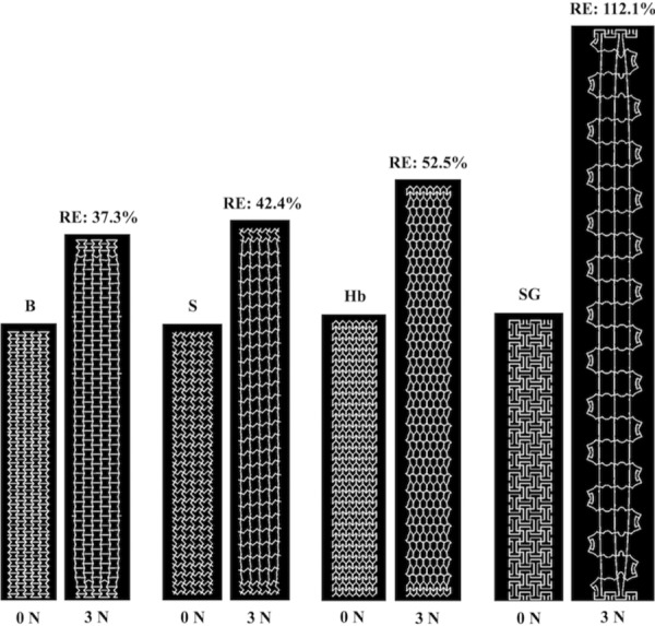
FEA results at 0 N and 3 N for the bowtie (B), spiral (S), hexagon(b) (Hb), and square grid (SG) auxetic models. Pore expansion is apparent for all models pictured. RE = relative elongation.
Fig. 8.
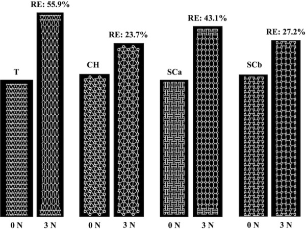
FEA results at 0 N and 3 N for the triangle (T), chiral hexagon (CH), square chiral(a) (SCa), and square chiral(b) (SCb) auxetic models. The triangles and circles within these models all contracted. RE = relative elongation.
Quantitatively assessing the deformation of the pores at 3 N, the minimal pore diameter of the diamond, square chiral(a), chiral hexagon, and square chiral(b) models decreased below 1 mm (see Supplemental Fig. 4, which is available under “Supplemental Data” tab for this paper on the ASME Digital Collection). The observed decrease in the minimal pore diameter also translated to a complete loss or decrease in the effective pore area for the previously mentioned models. The effective pore area was maintained at 100% for all other models (square, hexagon(a), bowtie, spiral, triangle, hexagon(b), and square grid). In addition to the effective pore area, the deformation of the pores was characterized via quantification of the porosity and effective porosity. In response to 3 N of force, the porosity decreased for the diamond and hexagon(a) models, while the porosity of the square model and all auxetic models increased. A decrease in the effective porosity was observed for the diamond, hexagon(a), and chiral hexagon models, whereas the effective porosity remained the same or increased for all other models in response to 3 N. See Table 2 for a summary of these results.
Table 2.
Characterization of pore deformation via quantification of the percent change in minimal pore diameter, effective pore area, porosity, and effective porosity
| CAD model | Minimal pore diameter % change | Effective pore area % change | Porosity % change | Effective porosity % change |
|---|---|---|---|---|
| Square | −3.9% | No changea | +2.7% | +2.7% |
| Diamond | −81.6% | −100% | −33.3% | −100.0% |
| Hexagon(a) | −43.5% | No changea | −12.5% | −12.5% |
| Bowtie | +113.0% | No changea | +25.9% | +25.9% |
| Spiral | −2.0% | No changea | +12.9% | +12.9% |
| Triangle | −30.2% | No changea | +14.5% | +14.5% |
| Square chiral(a) | −32.0% | −13.0% | +15.0% | No changeb |
| Chiral hexagon | −18.9% | −10.7% | +6.9% | −5.2% |
| Square chiral(b) | −32.7% | −12.3% | +15.3% | No changeb |
| Hexagon(b) | +125.0% | No changea | +21.4% | +21.4% |
| Square grid | +443.0% | No changea | +40.3% | +40.3% |
Initially, the effective pore area for all CAD models was 100%; thus, no change means that the effective pore area at 3 N was maintained at 100%.
No change—the effective porosity before (0 N) and after loading (3 N) are the same.
Interesting results were observed when assessing the expansion of the models via quantification of the relative lateral contraction (Fig. 9). The relative lateral contraction for the standard pore models was positive, signifying lateral contraction of these models, and this result was expected given that the pores of these models were nonauxetic. Consistent with auxetic behavior, the relative lateral contraction for all models with auxetic pores was negative at lower loads indicating lateral expansion. However, at 1.5 N and 2.4 N, the relative lateral contraction was positive and remained positive with additional loading for the triangle and chiral hexagon models, respectively. For all other models (the bowtie, spiral, square chiral(a), square chiral(b), hexagon(b), and square grid) the relative lateral contraction remained negative throughout loading signifying lateral expansion with the bowtie expanding the most.
Fig. 9.
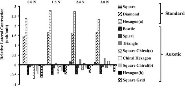
Relative lateral contraction results with increasing tension for both the standard and auxetic models. As anticipated, the relative lateral contraction was positive for the nonauxetic models for all levels of tension. Initially, the relative lateral contraction was negative for all auxetic models. However, at 1.5 N and 2.4 N, the relative lateral contraction was positive (and remained positive) for the triangle and chiral hexagon models, respectively. A positive value indicates model contraction, and a negative value indicates expansion.
4. Discussion
In this study, the behavior (i.e., pore deformation and the overall expansion or contraction) of synthetic mesh models with auxetic pore geometries in response to 3 N of uniaxial tension was assessed using computational modeling. For comparison, the behavior of models with standard pore geometries was also analyzed. Congruent with our hypothesis, models with auxetic pore geometries designed to expand in response to uniaxial loading did not experience pore collapse with loading. However, one important caveat to note is that using auxetic shapes as pore geometries does not guarantee that the pores will remain open and that the model as a whole will expand indefinitely. For example, the triangle and chiral hexagon models both displayed contraction at 3 N despite initially expanding at lower tensions. This suggests that the auxetic behavior is not maintained for all auxetic geometries with increasing tension. As anticipated, the models with standard pore geometries contracted and/or their pores collapsed with loading, and this result is consistent with ex vivo testing of commercial synthetic mesh products with similar pore geometries [3].
Given that the pores remained open for all models with auxetic pore geometries, the question of which auxetic geometry is best for POP repair arises. This study only investigated mesh geometries and loading conditions that are relevant to abdominal sacrocolpopexy. Based on the model assessment criteria outlined in Sec. 2.4, the square grid geometry is not appropriate for abdominal sacrocolpopexy given that the square grid pores rotated which resulted in significant pore deformation. This pore rotation allowed the square grid model to elongate more than any other model (more than doubling in length), which would necessitate the use of more material or a stiffer material to achieve the smaller deformed lengths observed in the other models. The auxetic geometries with circles (chiral hexagon, square chiral(a), and square chiral(b)) demonstrated contraction of the circles with loading which resulted in a minimal pore diameter that was less than 1 mm, ultimately decreasing the effective porosity. Meshes with pores less than 1 mm can become encapsulated due to bridging fibrosis—a phenomenon that has been associated with pain [26]. One way to overcome this limitation is to increase the diameter of the circles. However, this change would likely negatively impact the elongation of these designs, because there would be less material to resist the same amount of tension; thus, the chiral hexagon, square chiral(a), and square chiral(b) were determined to be inferior by our criteria.
Of the remaining four auxetic geometries (bowtie, spiral, triangle, and hexagon(b)), the relative lateral contraction of the triangle model was positive at 3 N, and therefore, the triangle auxetic geometry was excluded. The bowtie stood out as the most favorable geometry due to its increasing porosity and greater effective porosity with loading. The bowtie model also deformed the least and had the greatest increase in porosity and effective porosity compared to the spiral and hexagon(b) models. Additionally, relative to all other models, the relative lateral contraction was the most negative for the bowtie model. Given these promising results, the bowtie geometry shows significant potential and likely warrants focus of additional investigations. However, it is important to note that these qualities arise at the expense of increased elongation relative to the square pore standard geometry. Additionally, the uniaxial response to 3 N of tension for the bowtie model, and all other models simulated in this study, is specific to the direction in which it was loaded and to the amount of tension applied. Although not explored in this study, a rotation of the bowtie geometry by 45 deg with respect to the loading axis would likely result in destabilization of the pore with pore collapse and a decrease in the effective porosity. Similarly, increasing the amount of tension applied to the bowtie model (and all other auxetic models that experienced pore expansion) would likely alter the pore deformation and could possibly result in pores contracting and/or collapsing. Thus, the bowtie geometry may only be suited for sacrocolpopexy repairs within a certain range of tension.
Comparison of the behavior of the standard pore models, particularly the square pore model, to the auxetic models demonstrated the strengths of the auxetic pore geometry. Arguably, the square pore geometry performed just as well as the bowtie. In response to the applied load of 3 N, the pores of the square model remained open and the minimal pore diameter was greater than 1 mm. Additionally, the square model deformed the least overall, the effective pore area was maintained at 100%, and the porosity and effective porosity both increased for this model. However, the relative lateral contraction of the square model was positive, implying that the model contracted. In addition to the model contracting, the individual pores also contracted (from an average minimal diameter of 2.04 mm to 1.96 mm). Although minimal, it is important to note that this small amount of contraction is in response to a very low load (3 N), and we are utilizing an idealized geometry that does not account for the influence of the mesh knit pattern. In vivo, intra-abdominal forces are higher than 3 N with activities such as jumping, coughing, and sneezing. Additionally, the knit pattern can also contribute to changes in pore geometry with increasing tension that were not predicted in this study. With those caveats, it is nevertheless interesting that in vivo implantation studies by Feola et al. and Liang et al. showed that a square pore mesh performs better in terms of its impact on vaginal smooth muscle function and morphology as well as collagen and elastin content compared to other POP meshes with pore geometries that are more likely to collapse in response to tension [27,28]. These findings are congruent with what would be predicted based on the results of this study. However, it is also important to understand that other factors including the structural stiffness and weight of each mesh may have also contributed to those in vivo findings [10,22–25,27–31].
The way in which the auxetic and standard models were designed and evaluated is a major strength of this study. The aspect ratio (length to width), fiber width, and the amount of material (the volume) were consistent for all models. Other constraints on angulation and pore diameters allowed us to focus on specific designs based on clinical relevance. Additionally, this allowed for a reduction of the possible solution space for auxetic designs and a comparison between designs that minimized bias. By designing this study in this way, the impact of the pore geometry on the overall behavior of the model could be evaluated and compared as the dependent variable. Changing these parameters (e.g., increasing and decreasing angles, thickness, stiffness, etc.) will likely produce numerical values that are different from the ones reported in this study.
In addition, the utilization of FEA allowed for us to establish reasonable first approximations of mesh behavior with auxetic pores without the cost, time, and introduction of variables related to manufacturing and experimental testing if these tests were to have been performed on physical samples. However, FEA is also limiting in that the results obtained are theoretical predictions and must be validated. Thus, future studies will aim to manufacture and mechanically test the most promising model designs identified in this study.
As a final note, the term “mesh” is typically used to describe a textile that is knitted or woven. The models evaluated in this study are more appropriately described as mesh analogues since behaviors of knots and other factors (knit/weave patterns, etc.) were not simulated.
Overall, this work provides an initial proof of concept that constructing meshes with auxetic pore geometries can prevent pore collapse and mesh contraction. Based on the previous research highlighting the importance of pore size, this novel mesh design is likely to afford better ingrowth of host tissue into the pores, host integration of the mesh, and also decrease the likelihood of bridging fibrosis. Successfully designing an auxetic mesh, as described, may significantly reduce the occurrence of major mesh-related complications.
Supplementary Material
Supplementary Figure
Contributor Information
Katrina M. Knight, Department of Bioengineering, Musculoskeletal Research Center, University of Pittsburgh, 405 Center for Bioengineering 300 Technology Drive, Pittsburgh, PA 15219 e-mail: kmk144@pitt.edu
Pamela A. Moalli, Department of Obstetrics and Gynecology and Reproductive Sciences, Magee-Womens Research Institute, Magee Womens Hospital, University of Pittsburgh, 204 Craft Avenue, Pittsburgh, PA 15213 e-mail: moalpa@mail.magee.edu
Steven D. Abramowitch, Department of Bioengineering, Musculoskeletal Research Center, University of Pittsburgh, Magee-Womens Research Institute, Magee-Womens Hospital, University of Pittsburgh, 309 Center for Bioengineering 300 Technology Drive, Pittsburgh, PA 15219 e-mail: sdast9@pitt.edu.
Funding Data
National Science Foundation Graduate Research Fellowship Program (Grant No. DGE-1247842).
Office of the Assistance Secretary of Defense for Health Affairs, through Peer Reviewed Medical Research Program, U.S. Department of Defense (Grant No. W81XWH-16-1-0133).
References
- [1].U.S. Food and Drug Administration, 2011, “Surgical Mesh for Treatment of Women With Pelvic Organ Prolapse and Stress Urinary Incontinence—FDA Executive Summary,” U.S. Food and Drug Administration, Silver Spring, MD, accessed Jan. 29, 2018, http://www.thesenatorsfirm.com/documents/OBS.pdf
- [2]. Altman, D. , Väyrynen, T. , Engh, M. E. , Axelsen, S. , and Falconer, C. , 2011, “ Anterior Colporrhaphy Versus Transvaginal Mesh for Pelvic-Organ Prolapse,” New Engl. J. Med., 364(19), pp. 1826–1836. 10.1056/NEJMoa1009521 [DOI] [PubMed] [Google Scholar]
- [3]. Barone, W. R. , Moalli, P. A. , and Abramowitch, S. D. , 2016, “ Textile Properties of Synthetic Prolapse Mesh in Response to Uniaxial Loading,” Am. J. Obstet. Gynecol., 215(3), p. 326. 10.1016/j.ajog.2016.03.023 [DOI] [PMC free article] [PubMed] [Google Scholar]
- [4]. Feiner, B. , and Maher, C. , 2010, “ Vaginal Mesh Contraction: Definition, Clinical Presentation, and Management,” Obstet. Gynecol., 115(2), pp. 325–330. 10.1097/AOG.0b013e3181cbca4d [DOI] [PubMed] [Google Scholar]
- [5]. Feola, A. , Pal, S. , Moalli, P. , Maiti, S. , and Abramowitch, S. , 2014, “ Varying Degrees of Nonlinear Mechanical Behavior Arising From Geometric Differences of Urogynecological Meshes,” J. Biomech., 47(11), pp. 2584–2589. 10.1016/j.jbiomech.2014.05.027 [DOI] [PMC free article] [PubMed] [Google Scholar]
- [6]. Barone, W. R. , Amini, R. , Maiti, S. , Moalli, P. A. , and Abramowitch, S. D. , 2015, “ The Impact of Boundary Conditions on Surface Curvature of Polypropylene Mesh in Response to Uniaxial Loading,” J. Biomech., 48(9), pp. 1566–1574. 10.1016/j.jbiomech.2015.02.061 [DOI] [PMC free article] [PubMed] [Google Scholar]
- [7]. Otto, J. , Kaldenhoff, E. , Kirschner-Hermanns, R. , Mühl, T. , and Klinge, U. , 2014, “ Elongation of Textile Pelvic Floor Implants Under Load Is Related to Complete Loss of Effective Porosity, Thereby Favoring Incorporation in Scar Plates,” J. Biomed. Mater. Res. Part A, 102(4), pp. 1079–1084. 10.1002/jbm.a.34767 [DOI] [PubMed] [Google Scholar]
- [8]. Greca, F. H. , De Paula, J. B. , Biondo-Simões, M. L. P. , Da Costa, F. D. , Da Silva, A. P. G. , Time, S. , and Mansur, A. , 2001, “ The Influence of Differing Pore Sizes on the Biocompatibility of Two Polypropylene Meshes in the Repair of Abdominal Defects: Experimental Study in Dogs,” Hernia, 5(2), pp. 59–64. 10.1007/s100290100001 [DOI] [PubMed] [Google Scholar]
- [9]. Greca, F. H. , Souza-Filho, Z. A. , Giovanini, A. , Rubin, M. R. , Kuenzer, R. F. , Reese, F. B. , and Araujo, L. M. , 2008, “ The Influence of Porosity on the Integration Histology of Two Polypropylene Meshes for the Treatment of Abdominal Wall Defects in Dogs,” Hernia, 12(1), pp. 45–49. 10.1007/s10029-007-0276-6 [DOI] [PubMed] [Google Scholar]
- [10]. Klinge, U. , Klosterhalfen, B. , Birkenhauer, V. , Junge, K. , Conze, J. , and Schumpelick, V. , 2002, “ Impact of Polymer Pore Size on the Interface Scar Formation in a Rat Model,” J. Surg. Res., 103(2), pp. 208–214. 10.1006/jsre.2002.6358 [DOI] [PubMed] [Google Scholar]
- [11]. Orenstein, S. B. , Saberski, E. R. , Kreutzer, D. L. , and Novitsky, Y. W. , 2012, “ Comparative Analysis of Histopathologic Effects of Synthetic Meshes Based on Material, Weight, and Pore Size in Mice,” J. Surg. Res., 176(2), pp. 423–429. 10.1016/j.jss.2011.09.031 [DOI] [PubMed] [Google Scholar]
- [12]. Burriesci, G. , and Bergamasco, G. , 2007, “Annuloplasty Prosthesis With an Auxetic Structure,” U.S. Patent No. US8034103 B2.https://www.google.com/patents/US8034103
- [13]. Scarpa, F. , 2008, “ Auxetic Materials for Bioprostheses,” IEEE Signal Process. Mag., 25(5), pp. 126–128. 10.1109/MSP.2008.926663 [DOI] [Google Scholar]
- [14]. Mühl, T. , Binnebösel, M. , Klinge, U. , and Goedderz, T. , 2008, “ New Objective Measurement to Characterize the Porosity of Textile Implants,” J. Biomed. Mater. Res. Part B Appl. Biomater., 84(1), pp. 176–183. 10.1002/jbm.b.30859 [DOI] [PubMed] [Google Scholar]
- [15]. Cobb, W. S. , Burns, J. M. , Kercher, K. W. , Matthews, B. D. , James Norton, H. , and Todd Heniford, B. , 2005, “ Normal Intraabdominal Pressure in Healthy Adults,” J. Surg. Res., 129(2), pp. 231–235. 10.1016/j.jss.2005.06.015 [DOI] [PubMed] [Google Scholar]
- [16]. Howard, D. , Miller, J. M. , Delancey, J. O. , and Ashton-Miller, J. A. , 2000, “ Differential Effects of Cough, Valsalva, and Continence Status on Vesical Neck Movement,” Obstet. Gynecol., 95(4), pp. 535–540. 10.1016/S0029-7844(99)00618-3 [DOI] [PMC free article] [PubMed] [Google Scholar]
- [17]. Hsu, Y. , Chen, L. , Tumbarello, J. , Ashton-Miller, J. A. , and DeLancey, J. O. , 2010, “ In Vivo Assessment of Anterior Compartment Compliance and Its Relation to Prolapse,” Int. Urogynecol. J., 21(9), pp. 1111–1115. 10.1007/s00192-010-1154-9 [DOI] [PMC free article] [PubMed] [Google Scholar]
- [18]. Junginger, B. , Baessler, K. , Sapsford, R. , and Hodges, P. W. , 2010, “ Effect of Abdominal and Pelvic Floor Tasks on Muscle Activity, Abdominal Pressure and Bladder Neck,” Int. Urogynecol. J., 21(1), pp. 69–77. 10.1007/s00192-009-0981-z [DOI] [PubMed] [Google Scholar]
- [19]. Noakes, K. F. , Pullan, A. J. , Bissett, I. P. , and Cheng, L. K. , 2008, “ Subject Specific Finite Elasticity Simulations of the Pelvic Floor,” J. Biomech., 41(14), pp. 3060–3065. 10.1016/j.jbiomech.2008.06.037 [DOI] [PMC free article] [PubMed] [Google Scholar]
- [20]. Gao, S.-S. , Zhang, Y.-R. , Zhu, Z.-L. , and Yu, H.-Y. , 2012, “ Micromotions and Combined Damages at the Dental Implant/Bone Interface,” Int. J. Oral Sci., 4(4), pp. 182–188. 10.1038/ijos.2012.68 [DOI] [PMC free article] [PubMed] [Google Scholar]
- [21]. Holt, B. , Tripathi, A. , and Morgan, J. , 2008, “ Viscoelastic Response of Human Skin to Low Magnitude Physiologically Relevant Shear,” J. Biomech., 41(12), pp. 2689–2695. 10.1016/j.jbiomech.2008.06.008 [DOI] [PMC free article] [PubMed] [Google Scholar]
- [22]. Klinge, U. , Junge, K. , Stumpf, M. , Öttinger, A. P. , and Klosterhalfen, B. , 2002, “ Functional and Morphological Evaluation of a Low-Weight, Monofilament Polypropylene Mesh for Hernia Repair,” J. Biomed. Mater. Res., 63(2), pp. 129–136. 10.1002/jbm.10119 [DOI] [PubMed] [Google Scholar]
- [23]. Klinge, U. , Klosterhalfen, B. , Conze, J. , Limberg, W. , Obolenski, B. , Öttinger, A. P. , and Schumpelick, V. , 1998, “ Modified Mesh for Hernia Repair That Is Adapted to the Physiology of the Abdominal Wall,” Eur. J. Surg., 164(12), pp. 951–960. 10.1080/110241598750005138 [DOI] [PubMed] [Google Scholar]
- [24]. Klinge, U. , Klosterhalfen, B. , Muller, M. , Ottinger, A. P. , and Schumpelick, V. , 1998, “ Shrinking of Polypropylene Mesh In Vivo: An Experimental Study in Dogs,” Eur. J. Surg., 164(12), pp. 965–969. 10.1080/110241598750005156 [DOI] [PubMed] [Google Scholar]
- [25]. O'Dwyer, P. J. , Kingsnorth, A. N. , Molloy, R. G. , Small, P. K. , Lammers, B. , and Horeyseck, G. , 2005, “ Randomized Clinical Trial Assessing Impact of a Lightweight or Heavyweight Mesh on Chronic Pain After Inguinal Hernia Repair,” Br. J. Surg., 92(2), pp. 166–170. 10.1002/bjs.4833 [DOI] [PubMed] [Google Scholar]
- [26]. Nolfi, A. L. , Brown, B. N. , Liang, R. , Palcsey, S. L. , Bonidie, M. J. , Abramowitch, S. D. , and Moalli, P. A. , 2016, “ Host Response to Synthetic Mesh in Women With Mesh Complications,” Am. J. Obstet. Gynecol., 215(2), pp. 206.e1–206.e8. 10.1016/j.ajog.2016.04.008 [DOI] [PMC free article] [PubMed] [Google Scholar]
- [27]. Feola, A. , Abramowitch, S. , Jallah, Z. , Stein, S. , Barone, W. , Palcsey, S. , and Moalli, P. , 2013, “ Deterioration in Biomechanical Properties of the Vagina Following Implantation of a High-Stiffness Prolapse Mesh,” BJOG: Int. J. Obstet. Gynaecol., 120(2), pp. 224–232. 10.1111/1471-0528.12077 [DOI] [PMC free article] [PubMed] [Google Scholar]
- [28]. Liang, R. , Abramowitch, S. , Knight, K. , Palcsey, S. , Nolfi, A. , Feola, A. , Stein, S. , and Moalli, P. A. , 2013, “ Vaginal Degeneration Following Implantation of Synthetic Mesh With Increased Stiffness,” BJOG: Int. J. Obstet. Gynaecol., 120(2), pp. 233–243. 10.1111/1471-0528.12085 [DOI] [PMC free article] [PubMed] [Google Scholar]
- [29]. Goel, V. K. , Lim, T. H. , Gwon, J. , Chen, J. Y. , Winterbottom, J. M. , Park, J. B. , Weinstein, J. N. , and Ahn, J. Y. , 1991, “ Effects of Rigidity of an Internal Fixation Device. A Comprehensive Biomechanical Investigation,” Spine, 16(3), pp. S155–S161. 10.1097/00007632-199103001-00023 [DOI] [PubMed] [Google Scholar]
- [30]. Jallah, Z. , Liang, R. , Feola, A. , Barone, W. , Palcsey, S. , Abramowitch, S. , Yoshimura, N. , and Moalli, P. , 2015, “ The Impact of Prolapse Mesh on Vaginal Smooth Muscle Structure and Function,” BJOG: Int. J. Obstet. Gynaecol., 123(7), pp. 1076–1085. 10.1111/1471-0528.13514 [DOI] [PMC free article] [PubMed] [Google Scholar]
- [31]. Rumian, A. P. , Draper, E. R. , Wallace, A. L. , and Goodship, A. E. , 2009, “ The Influence of the Mechanical Environment on Remodelling of the Patellar Tendon,” J. Bone Joint Surg. Br., 91(4), pp. 557–564.https://www.ncbi.nlm.nih.gov/pubmed/19336822 [DOI] [PubMed] [Google Scholar]
Associated Data
This section collects any data citations, data availability statements, or supplementary materials included in this article.
Supplementary Materials
Supplementary Figure


