Abstract
Endovascular and endoscopic surgical procedures require micro-scale and meso-scale continuum robotic tools to navigate complex anatomical structures. In numerous studies, fiber Bragg grating (FBG) based shape sensing has been used for measuring the deflection of continuum robots on larger scales, but has proved to be a challenge for micro-scale and meso-scale robots with large deflections. In this paper, we have developed a sensor by mounting an FBG fiber within a micromachined nitinol tube whose neutral axis is shifted to one side due to the machining. This shifting of the neutral axis allows the FBG core to experience compressive strain when the tube bends. The fabrication method of the sensor has been explicitly detailed and the sensor has been tested with two tendon-driven micro-scale and meso-scale continuum robots with outer diameters of 0.41 mm and 1.93 mm respectively. The compact sensor allows repeatable and reliable estimates of the shape of both scales of robots with minimal hysteresis. We propose an analytical model to derive the curvature of the robot joints from FBG fiber strain and a static model that relates joint curvature to the tendon force. Finally, as proof-of-concept, we demonstrate the feasibility of our sensor assembly by combining tendon force feedback and the FBG strain feedback to generate reliable estimates of joint angles for the meso-scale robot.
Index Terms—: Medical Robots and Systems, Surgical Robotics: Steerable Catheters/Needles, Mechanism Design
I. Introduction
PERIPHERAL artery disease (PAD) is a commonly occurring condition affecting approximately 155 million people worldwide in 2015 and increasing in number by about 34.4% from 2005 to 2015 [1]. Minimally invasive surgery (MIS) required to treat this condition involves the manual navigation of a thin metallic wire (with outer diameters ranging from 0.36 mm to 0.89 mm [2]), known as a ‘guidewire’ through tortuous vascular anatomy to reach an obstructed or diseased artery. This manual navigation of the guidewire is effortful and requires significant experience [3]. Following the insertion and navigation of the guidewire to the diseased artery, a variety of catheters may be introduced over this guidewire to perform various tasks at the diseased artery location. Steerability in these guidewires would therefore greatly reduce overall clinician time and effort in a PAD procedure. Steerable micro-catheters and guidewires employ a variety of actuation strategies to manipulate their distal ends [4]. The shape memory effect demonstrated by Nitinol [5], [6] as well as its superelasticity [7], [8] and machinability make this material a very desirable candidate for steerable guidewires. The design of reliable, actively steerable guidewires is an active field of research. In the past, we have proposed the design, analysis and control of a micro-scale 2 degree-of-freedom robotic guidewire with an outer diameter (OD) of 0.78 mm [9]. In this work, we use a miniaturized version of this design with OD = 0.41 mm. The guidewire has a set of four tendon-driven joints that allow it to achieve high bending angles while navigating through tortuous vasculature (see Fig. 1(a)).
Fig. 1:
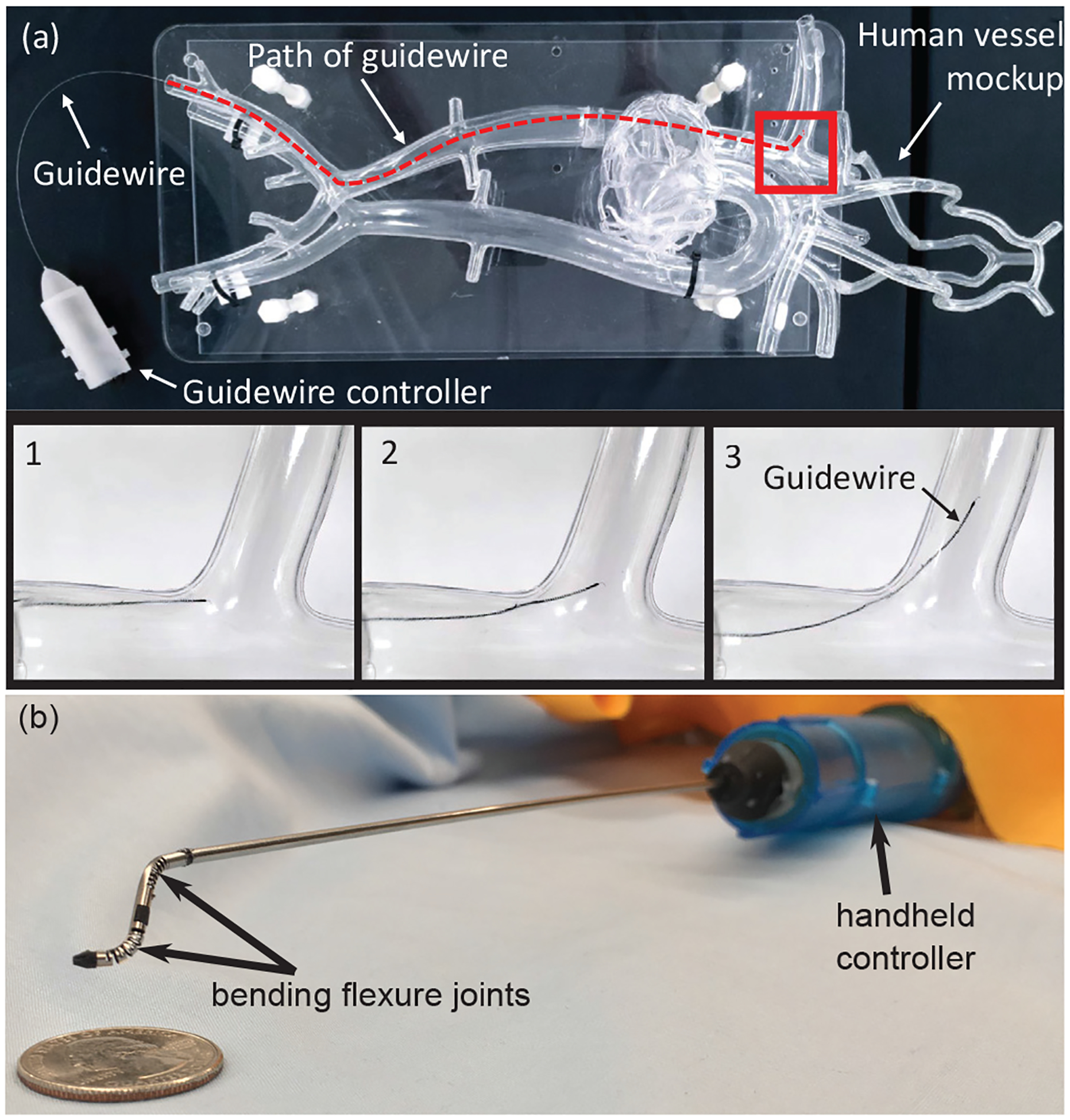
(a) Micro-scale robotic guidewire (OD: 0.41 mm) with four bending flexure joints traversing vascular phantom model, (b) Meso-scale neuroendoscopic robotic tool tip (OD: 1.93 mm) with two degrees-of-freedom forming S-shaped curve using tendon driven bending flexure joints.
Micro-scale and meso-scale robotic tools are required in both pediatric and adult endoscopic procedures. For example, in a pediatric MIS neuroendoscopic procedure known as the endoscopic third ventriculostomy (ETV), a variety of rigid tools with diameters in the range of 1 mm - 2 mm are used to reach several target regions in the third ventricle of the patient’s brain [10]. However, an inability to manipulate the curvature of the tools inside the ventricles drastically reduces the workspace of the clinician, causing the clinician to reach sub-optimal target locations. Several solutions have been suggested for the use of steerable robotic tools formed using pre-curved concentric tubes [11] as well as tendon driven actuation [12]. In our previous work, we proposed a two degree-of-freedom (2-DoF) meso-scale robotic neuroendoscopic tool with a diameter of approximately 2 mm with a handheld controller [13]. We use a modified version of the same tool with a diameter of 1.93 mm in this work (see Fig. 1(b)).
In each of the above cases (micro-scale and meso-scale robots), shape sensing is necessary to improve the control-performance and to enable the surgeon to be aware of the robotic tool’s position relative to patient anatomy as well as guide the imaging modality. Electromagnetic (EM) tracking and image-based sensing have both been used for shape sensing in robotics [14]. However, in the operating room (OR), EM tracking may suffer from the interference of other magnetic or conductive objects within the generated field [14]. Image-based tracking methods in the OR often require the use of radiation, which should be minimized when possible, according to the current radiation safety practices [14]. Ultrasound suffers from low resolution, low signal-to-noise ratio, and imaging artifacts which makes it ill-suited to track a guidewire tip as it traverses through different areas of the body [14]. Another viable option for tendon-driven continuum robots is to use tendon data (tendon stroke and tendon tension) to estimate the shape of the robot via kinematic and static models of the robot [9]. However, this modality is susceptible to errors arising from variable tendon-sheath friction and the resulting tendon axial strain variability. Furthermore, external robot tip forces arising from interactions with vascular or ventricular walls may cause error in control and shape reconstruction based solely upon tendon data (see Section IV). Therefore, this modality cannot be solely used to reconstruct robot shape.
Fiber Bragg grating (FBG) sensing is a promising technology where gratings etched into a fiber reflect light at a wavelength that correlates with the space between gratings and thus, the strain of the fiber. FBG fibers have been previously studied for shape sensing in various applications. Liu et al. have developed an FBG bending sensor by attaching a fiber to two nitinol wires and routing the assembly through the walls of their continuum robot [15]. This design was later improved to insert the fiber and wires through the lumen of a polycarbonate tube, bonding them at the ends, and has been tested up to a curvature of 66.7 m−1 [16]. Furthermore, it was implemented in the optimization-based control of a 6 mm diameter continuum manipulator [17]. However, this method requires a channel to guide it along the length of the robot which is not always available in the micro-scale and meso-scale robots under consideration in this paper. We have previously developed large deflection FBG sensors that can measure similar curvatures for larger robots [18], [19]. Other groups have also worked with FBG bending sensors, but their maximum reported curvatures are less than 14 m−1 [20]–[22]. Therefore, shape-sensing is still an open problem in small scale continuum robots with large deflections. This paper presents an FBG-based bending sensor design to provide accurate large deflection sensing for micro-scale and meso-scale continuum robotic tools with a maximum measured curvature of 145 m−1.
This paper is organized as follows: Section II describes the assembly of the FBG fiber within the joints of each of the robots in Fig. 1. Section III introduces two models for this sensor assembly: A model to estimate joint curvature from FBG fiber strain (Section III-A) and a relationship between tendon tension and joint curvature for the meso-scale joint (Section III-B). Finally, in Section IV we demonstrate the feasibility of this sensing technique by implementing a Kalman filter based observer that takes into account the FBG strain and tendon tension to estimate the meso-scale robot’s joint angles.
II. Shape Sensor and Joint Assembly
The tendon-driven joints of the micro-scale and meso-scale robots considered in this work are called bending flexure joints [23], [24] (see Fig. 1(b)). These joints are created by micromachining a set of notches in a tube of superelastic nitinol material using a femtosecond laser (Optec Laser S.A., Frameries, Belgium), allowing 1-DoF compliance in the tube at the location of the notches. The pattern of notches machined in the tube determines the bending properties of the notch joint. The joints employed in the micro-scale robotic guidewire are termed unidirectional asymmetric notch (UAN) joints [25], [26] (see Fig. 2(a)) while the meso-scale neuroendoscopic robotic tool consists of bidirectional asymmetric notch (BAN) joints [9], [27], [28] (see Fig. 2(b)).
Fig. 2:
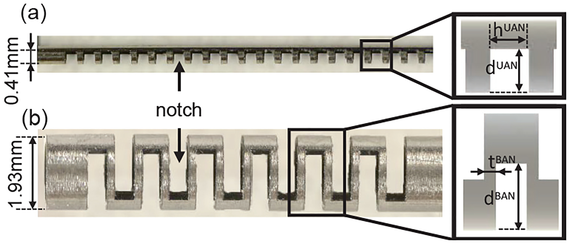
Tendon-driven bending flexure joints: (a) Micro-scale UAN joint and the notch parameters defining its bending properties (inset), (b) Meso-scale BAN joint and the notch parameters defining its bending properties (inset).
Bending flexure joints allow for high joint curvatures at small joint lengths (each joint length in our case is 12 mm). However, due to the low wall thickness of the nitinol tubes used for machining these joints, explicit tendon routing channels cannot be machined into the walls of the tube. This lack of space in the robot also limits the options for the placement of FBG fibers in each joint to measure joint deflection. Unlike the authors in [16], the tendons and FBG fibers cannot be routed in dedicated channels within the walls of the tube. The fibers are therefore routed along the central lumen of the bending flexure joints. Furthermore, since FBG fibers cannot measure pure bending strain and can only measure axial strain, the neutral axis of the sensor assembly must be shifted away from the central axis of the joint. Authors in [15], [16], solve this problem by attaching two nitinol wires to a single FBG fiber, thereby adding an offset to the neutral axis of this sensor-wire assembly. However, this design is too large to fit in the central lumen of our micro-scale robot and tendons for tool control must be routed with the sensor through the central lumen of our meso-scale robot, which may affect an unprotected fiber. Hence, this is not a feasible solution.
In this section, we will first address each of these problems for the meso-scale robot joint and then proceed to modify the solution for the joint of the micro-scale guidewire.
A. Meso-scale joint assembly
Fig. 3 shows the steps to assemble an FBG fiber inside the meso-scale BAN joint. A central ‘spine’ for the entire robot is created (shown in blue in Fig. 3) by micromachining a passive UAN joint from a nitinol tube of OD 0.57 mm and ID 0.44 mm. This ‘spine’ can run along the central axis of the entire joint. To assemble the fiber within the spine, the spine is first placed in a jig, held in place at both ends with a set of supports with sliding dovetail joints (see Step 1 in Fig. 3). Each of these spine supports has a metallic routing plate embedded in it. The routing plate is also micromachined using a femtosecond laser from a sheet of nitinol approximately 0.08 mm in thickness. This plate has slots to ensure the correct orientation of the spine, as well as holes to hold the FBG fiber in place. Once the spine is held in place by the supports and oriented correctly using the plate, the fiber is inserted via the hole inside the metal routing plates of the supports at both ends of the spine. The fiber used is a Draw Tower Grating (DTG) based fiber (FBGS International NV, Geel, Belgium) of diameter 195 μm with a single grating of length 8 mm. Glue (ClearWeld Quick Setting Epoxy, J-B Weld, Atlanta, United States) is then applied through the two slots micromachined on either side of the notches to attach the fiber to the ends of the spine (see Step 2 in Fig. 3) such that the grating is located in the middle of the spine. The glue is allowed to cure overnight with the assembly held in place by the jig. Next, the spine is extracted from the jig and inserted into the meso-scale BAN joint of the robot (see Step 3 in Fig. 3). The spine, along with the joint, is held in place by two 3D printed connectors at each end of the joint (see Step 4 in Fig. 3). A single tendon is routed to the distal end of the meso-scale joint during this assembly, allowing the control of the active robot joint. The passive UAN spine is oriented such that it bends in the same direction as the meso-scale BAN joint (see Step 5 (inset) in Fig. 3) Therefore, when the tendon is actuated, the robot and the spine-fiber assembly are assumed to have similar curvatures (see Section III-A). It is important to note that the fiber will always run along the back wall (the side of the joint without the notches) of the spine due to the specific placement of the neutral axis of the UAN joint regardless of where the two ends of the fiber are glued around the inner circumference of the spine (see Section III-A for more details).
Fig. 3:
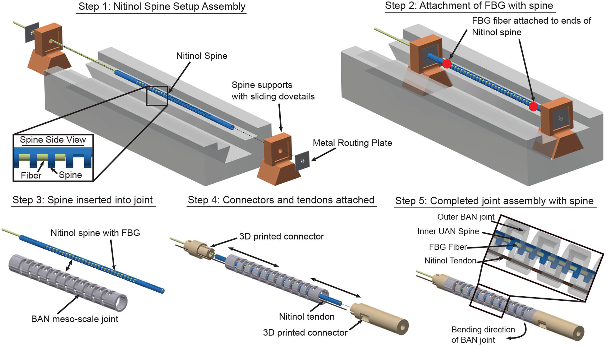
Steps to affix the FBG fiber within a spine for the meso-scale BAN joint.
B. Micro-scale joint assembly
Fig. 4 shows the steps to assemble an FBG fiber inside the micro-scale UAN joint. The process is similar to the assembly of the spine for the meso-scale BAN joint described above. The guidewire is manufactured by using a femtosecond laser to micromachine a 12 mm long UAN joint from a nitinol tube of OD 0.41 mm and ID 0.24 mm. Two routing plates are also micromachined and placed on the sliding supports of the assembly jig (see Step 1 in Fig. 4). The guidewire is inserted in the supports and oriented so that when the FBG is placed, it will run along the un-notched side of the UAN joint of the guidewire (see Step 2 in Fig. 4). The FBG fiber used has a diameter of 160 μm with a single grating of length 8 mm (Technica Optical Components, Atlanta, United States). Due to the small difference between the ID of the guidewire and the OD of the FBG fiber, only a single hole for the fiber can be cut in the routing plate, requiring that the guidewire be visually aligned under a microscope. The FBG fiber is pushed through the routing plates and the guidewire joint such that the gratings on the fiber lie entirely inside the joint and at the middle of the joint (see Step 3 in Fig. 4). Once the alignment of the guidewire and fiber is confirmed, a light adhesive tape is gently placed over the ends of the fiber to ensure that they remain pressed against the un-notched wall of the guidewire and to prevent the fiber from shifting during the glueing process. Glue is applied through the two slots on either side of the notches to attach the fiber to the un-notched wall at the ends of the guidewire joint. The entire assembly rig is then flipped so that the notches face upward and the still liquid glue will not occlude the inside of the guidewire. Once the glue has cured overnight, the guidewire joint is removed from the assembly rig and two 50 μm nitinol tendons are routed from the proximal end to where they are pulled out of a slot on the notched side at the distal end of the guidewire. The distal ends of the two tendons are tied together, tension is applied and they are glued in place to the outer wall of the joint.
Fig. 4:
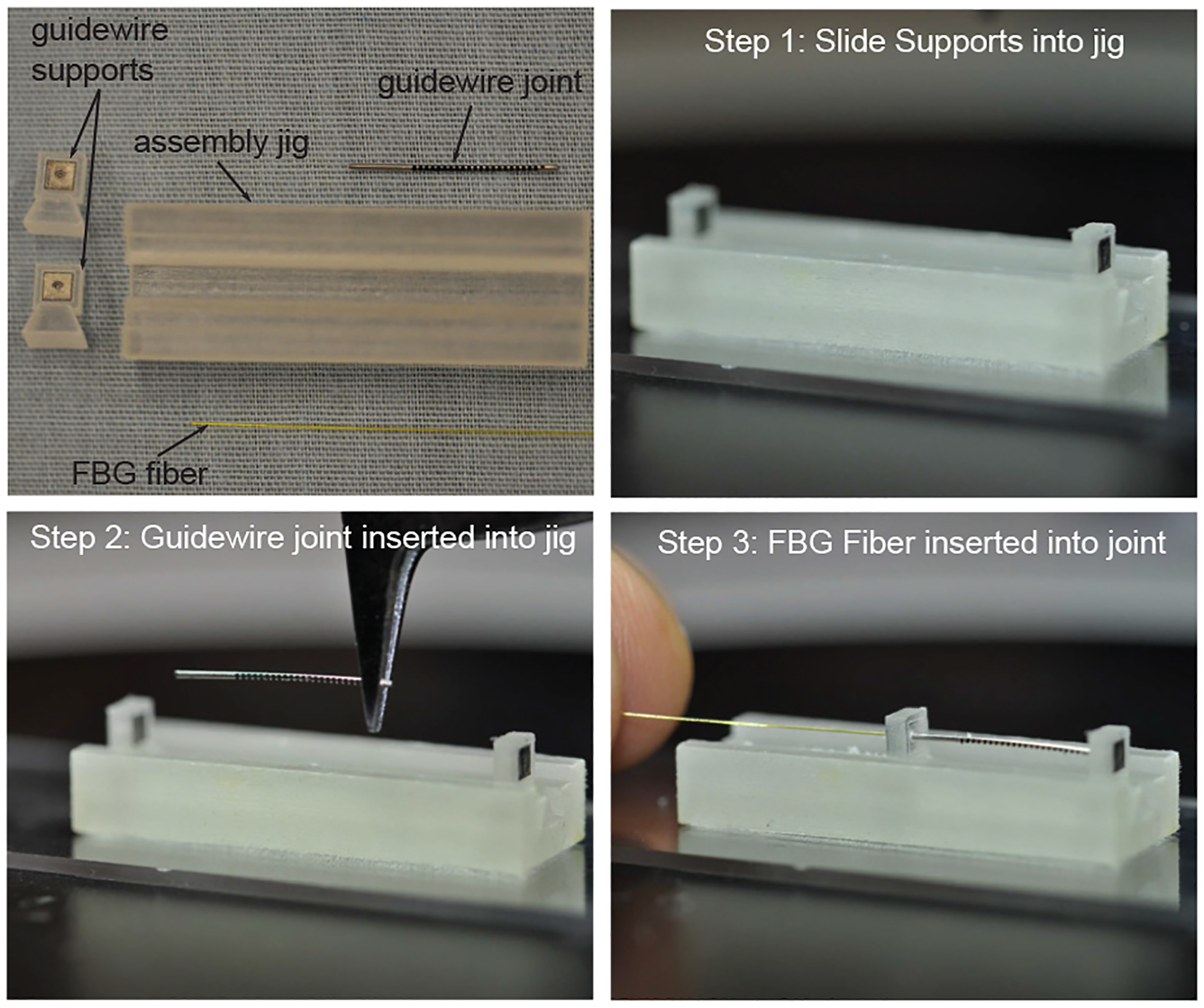
Assembly process for inserting the FBG fiber into the joint of a robotic guidewire with an outer diameter of 0.41 mm.
III. Joint and Fiber Models
In this section, we model the relationship between the deflection of the joint and the obtained strain in the FBG fiber for the meso-scale and micro-scale bending flexure joints. For the meso-scale robot, we used a BAN joint, where the FBG fiber is routed through the center of the joint via a central spine. In our previous work [9], we have demonstrated the feasibility of using tendon forces as feedback for shape-estimation for BAN joints. However, the addition of a central spine changes the static model of the BAN joint which must also be modeled.
A. Micro/Meso-scale Robot: Strain-Joint Angle Relationship
In FBG sensors, the axial strain (ϵ) in the fiber-core causes a change in the wavelength of light reflected back by the fiber (Δλ). Two different types of FBG sensors were used for the two scales of robots tested in this work. For the meso-scale joints of the neuroendoscope robot tool, Draw Tower Gratings (DTGs) with an outer diameter (DDTG) of 195 μm are used. For the micro-scale guidewire, FBG fibers manufactured with a smaller outer diameter (DFBG) of 160 μm were used. For DTG fibers, the relationship between the change in wavelength (Δλ) and the axial strain (ϵ) of the DTG fiber is given by the manufacturer (FBGS International NV, Geel, Belgium) as follows:
| (1) |
where ΔT is the change in temperature relative to the value upon initialization of the measurements. Also, λ1 = 1579 nm is the nominal wavelength of the DTG fiber, kϵ.1 = 0.772 is the strain sensitivity and ST.1 = 6.37 × 10⁻⁶ and ST.2 = 7.46 × 10⁻⁹ are the temperature sensitivities provided by the manufacturer. For standard FBG sensors, the governing equation for the Δλ-ϵ relationship is as follows [16]:
| (2) |
Here, the constants kϵ.2 = 1.2 pm/μϵ and ST.3 = 10 pm/°C are intrinsic characteristics of the fiber and λ2 = 1550 nm is the nominal wavelength of the FBG provided by the manufacturer (Technica Optical Components, Atlanta, United States). Temperature variation can be accounted for using the governing equation for the fiber or by introducing a second, reference grating below the joint that is unattached to the guidewire wall so that it is not strained by changes in curvature. Since this work is performed in a controlled laboratory environment, the temperature is assumed to be constant (ΔT = 0) and hence the change in wavelength is only related to strain. In the case of the meso-scale bending flexure joints considered in this work, the sensing fiber is contained within a spine which itself is a passive UAN joint. In the case of the robotic guidewire, the robot’s joint itself acts as the spine in which the fiber is fixed. We denote the outer and inner radii of these spines as and respectively (see Fig. 5(a)). Also, the depth of the unidirectional asymmetric notches in the spine is denoted as dspine. The distance between the neutral plane and central axis of the spine is given as and is a function of the cross-sectional area Aspine [25] (see Fig. 5(b) (inset)). Aspine is a function of , , and dspine. Furthermore, the location of the neutral axis of the FBG from the same central axis (see black dashed-dotted line in Fig. 5(a)) is given as follows:
| (3) |
As previously defined, Dfiber = {DDTG, DFBG} is the outer diameter of the fiber used in each case (DTG or FBG). In the case of each of the joints in this paper, we ensure that the Dfiber and dspine are selected such that . This ensures that the fiber is always undergoing compression when the spine is curved and will always rest along the back wall of the UAN joint (the side of the joint without the notches). The neutral axis of the composite structure composed of the fiber and spine is then given by:
| (4) |
Fig. 5:
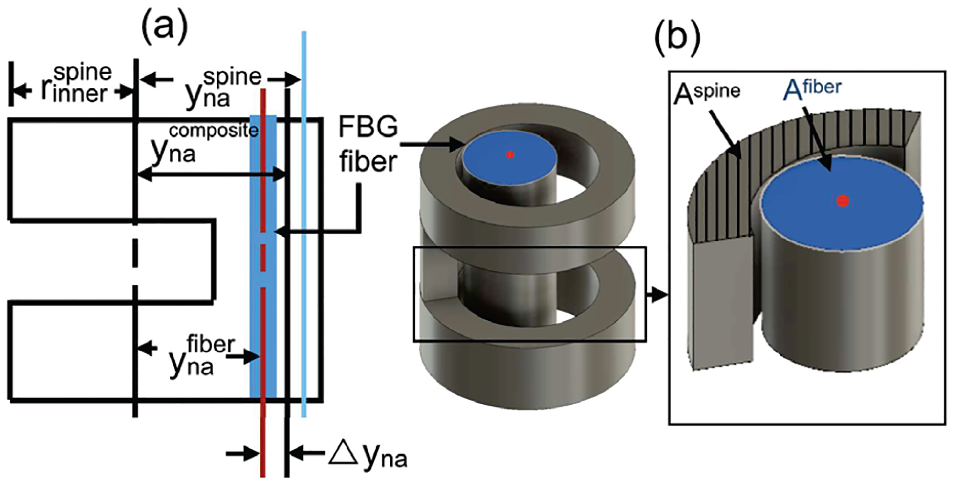
Micro/Meso-scale Robot Joints: (a) Schematic of the neutral axes of the spine, the FBG fiber, and the composite structure, (b) Schematic of the notch and integrated fiber.
Here, is the cross-sectional area of the fiber (see Fig. 5(b)), while Espine = 75 GPa and Efiber = 70 GPa are the Young’s modulus for the spine and fiber respectively [15]. Furthermore, the distance of the fiber from this composite neutral axis is given by . The strain along the fiber (ϵ) for spine angle θ (see Fig. 6) is then given as follows:
| (5) |
Here Lθ is the length of the FBG at the joint angle of θ, estimated as , where κ is the curvature. Substituting this value of strain, ϵ, in Eqs. (1) and (2), we can get the θ-Δλ relationship for the micro-scale (UAN) joint as follows:
| (6) |
For the meso-scale joint, this relationship is given as follows:
| (7) |
Fig. 6:
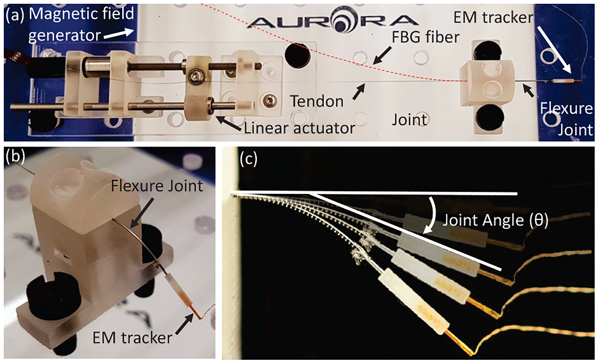
Experimental setup for sensor validation.
It is worth mentioning that and are the most critical factors that affect the axial strain of the fiber. Since is located inside the back-wall of the spine, the minimum distance between and depends on the wall thickness of the spine. In the current design, the fiber is always compressed when the tendon is been pulled. Any machining of the nitinol tube for attaching the FBG fiber on the spine changes the and hence the sensitivity of the sensor assembly. To evaluate the model derived in Eqs. (6)–(7), we conducted experiments on the guidewire (UAN) and neuroendoscope (BAN) joints. The experimental setup is shown in Fig. 6. For each test, a DC motor with a lead screw (Maxon Precision Motors, MA, United States) was attached to the tendon for the UAN/BAN joint with the FBG sensor assembled inside. The θ-Δλ relationship has been tested on one micro-scale UAN joint (see joint J1 in Table I) and one meso-scale joint (see joint J2 in Table I). An electromagnetic (EM) tracking system (Northern Digital Inc. Medical Ontario, Canada) was used to record the true bending angle of each sample. Figure 7(a)–(b) illustrates the comparison between the modeled θ-Δλ relationship and the experimental data. For the joint loading case, we find the model has an R2-value of 0.991 for the micro-scale (UAN) joint and 0.996 for the meso-scale (BAN) joint. Note that while the ϵ-Δλ relationship is nonlinear for the DTG fiber in the meso-scale joint (see Eq. (1)), it demonstrates a high degree of linearity over its operating range (ϵ ≤ 7%). As a result, the R2-value is reported for this case to maintain consistency. However, we observe hysteretic behavior in the experimental data during unloading of the joints (see Fig. 7(a)–(b)). As a result, for the joint unloading case, we have lower R2-values of 0.886 for the micro-scale (UAN) joint and 0.962 for the meso-scale (BAN) joint. This hysteresis effect is addressed for the meso-scale robot in Section IV.
TABLE I:
The set of samples tested to validate the spine-joint static model.
| Parameters | ||||||
|---|---|---|---|---|---|---|
| Sample | t (mm) |
d (mm) |
h (mm) |
Notches |
R2-valuec - |
RMSEd (N) |
| J1a | - | 0.27 | 0.3 | 28 | 0.991 | - |
| J2b | 0.2 | 1.09 | - | 20 | 0.996 | 0.071 |
| J3b | 0.2 | 1.20 | - | 20 | - | 0.077 |
J1 is unidirectional asymmetric notch joint in micro-scale robot (Guidewire).
J2 and J3 are bidirectional asymmetric notch joints in meso-scale robot (Neuroendoscope).
are the R2-values for the θ-Δλ model developed in Section III-A.
are the RMSE values for the θ-Ftotal model developed in Section III-B.
Fig. 7:
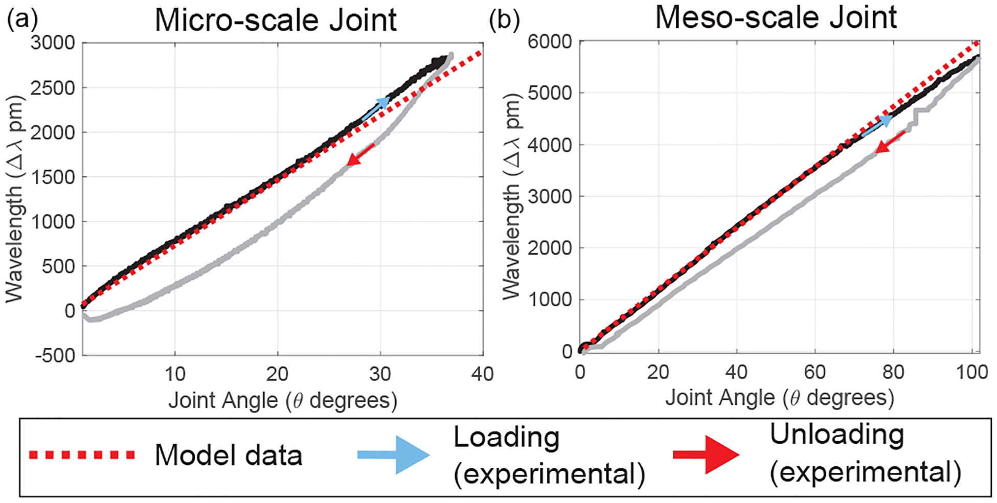
Comparison between the Joint Angle (θ)-Wavelength Shift (Δλ) model (during joint loading) and the experimental data demonstrating hysteresis in the (a) Micro-scale joint, (b) Meso-scale joint.
B. Meso-scale Robot: Spine-Joint Static Relationship
To arrive at a static relationship for the spine-joint assembly of the meso-scale joint, we made two assumptions: 1) The stiffness of the FBG fiber is negligible in comparison to that of the joint and the spine and therefore it is not considered in the development of the static model of the joint, 2) Joint statics are affected by bending moments, tendon friction, and pure compression forces. However, in these joints, pure compression is insignificant in comparison to the bending and friction forces and is not incorporated into our model. Fig. 8(a) shows an FEM simulation (Solidworks 2018, Dassault Systems) of a BAN joint, spine and nested joint including a spine inside of the lumen of the BAN joint. Because the neutral axes of the BAN joint and the spine are on the same plane but not statically connected as a single body, the total moment applied on the nested joint by the tendon (Mtotal) can be stated as a superposition of the moments applied to the joint (Mjoint) and spine (Mspine): Mtotal = Mjoint + Mspine. These moments are applied to the FEM model, and the model validates this moment superposition relationship (see dashed line in Fig. 8(b)). Here Mi = FiLarm is the moment applied on the joint, the spine or the joint-spine combination due to the tendon tension Fi, where i = {joint, spine, total}. Since the moment arm (Larm) is the same for all three cases, we can represent this equation as follows:
| (8) |
For the outer BAN joint, the outer radius of the tube , depth of the notches (dBAN), and the thickness of the segment between two consecutive notches (tBAN) are the parameters defining the statics (see Fig. 2(b)). From [13], a BAN joint is modeled as a serial chain of N bidirectionally asymmetric notches. Using Castigliano’s second theorem:
| (9) |
Fig. 8:
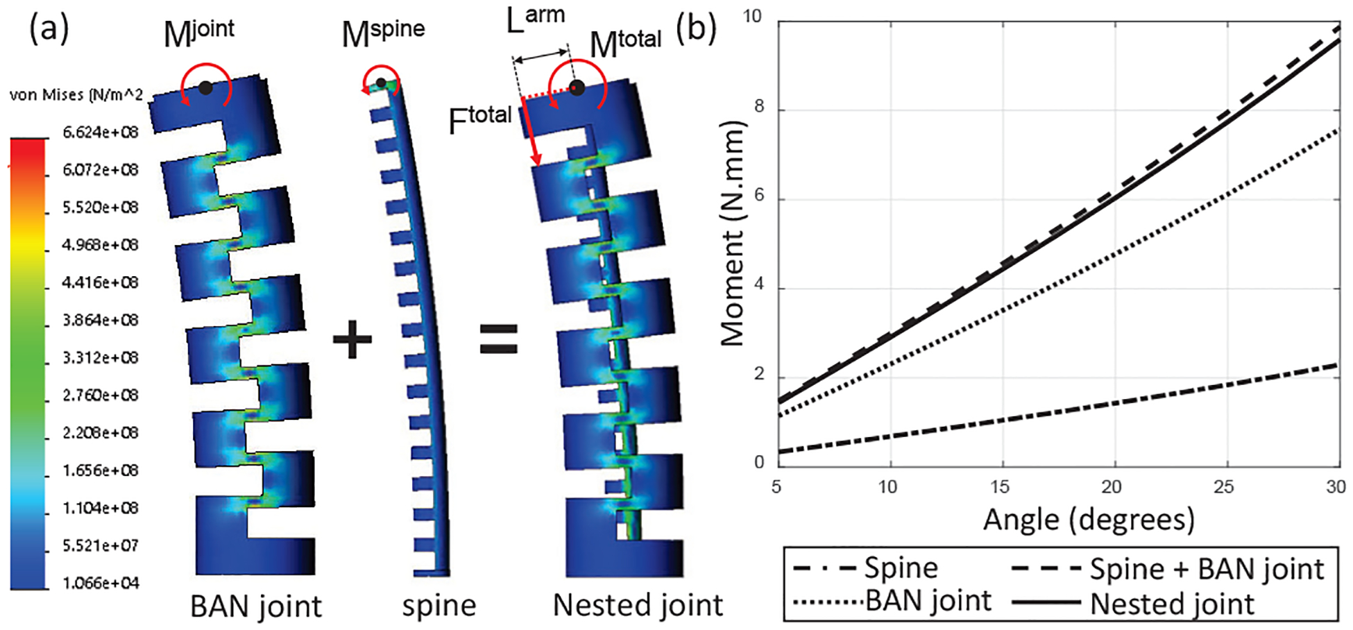
(a) The nested joint model in FEM simulation and (b) FEM result.
where N is the total number of notches in the joint, U(tBAN, dBAN) is the strain energy across the bending section for a single pair of notches, and is the moment applied on the single pair of notches due to the tendon tension F joint. Using Eq. (8), we can find the tendon tension required to achieve the bending angle (θ) for any BAN joint.
To find the θ-Fspine relationship, we make use of joint loading experimental data from joint ‘J3’ in Table I. The experimental setup of Fig. 6 is used, replacing the micro-scale guidewire joint with the larger meso-scale BAN joint ‘J3’ with and without the FBG sensor assembly. A second order polynomial fit is generated to approximate the θ-Ftotal and θ-Fjoint relationships (see Fig. 9(a)). Using Eq. (8) and these polynomial approximations of experimental data, we can arrive at the θ-Fspine relationship. This relationship can then be applied to a model of joint ‘J2’ (see dotted blue and green lines in Fig. 9(b) generated using Eq. (9)) to arrive at an accurate model for the joint behavior with the spine (see solid blue line in Fig. 9(b)). Therefore, the effect of the sensor assembly on the statics of the meso-scale robot joint can be effectively modeled (RMSE values for joints ‘J2’ and ‘J3’ are 0.071 N and 0.077 N respectively). However, as seen in Fig. 9(b), the model holds only for the case of joint loading. A significant amount of hysteresis is observed in the θ-Ftotal relationship during the unloading of the joint. This hysteresis results from the material properties of the nitinol material used to manufacture the BAN joint. Superelastic nitinol demonstrates hysteresis in its stress-strain relationship as it transitions between its austenite and martensite phases. We compensate for this hysteresis in the next section.
Fig. 9:
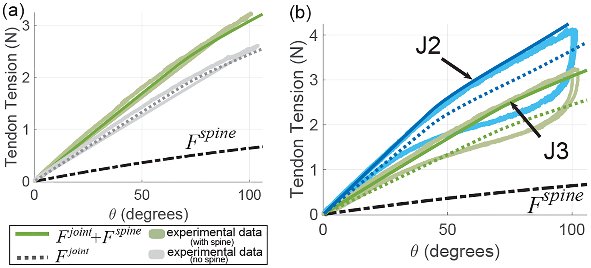
(a) For the joint ‘J3’ in Table I, the gray and green colored solid lines allow us to estimate Fspine, (b) Bidirectional asymmetric notch joints with spine containing a single FBG fiber (joints J2 and J3 in Table I).
IV. Meso-scale Robot: Joint State Estimation
In the case of the micro-scale guidewire joint, FBG sensing is the only feasible modality available to estimate the shape of the guidewire other than imaging. Tendon force or displacement proves to be unreliable in this case due to varying tendon-sheath friction forces as the guidewire traverses through the patient’s vasculature towards the target. However, for tools with a fixed sheath length (such as the meso-scale robotic neuroendoscope), tendon force too (Ftotal) can be an effective feedback mechanism to estimate robot joint state. However, since the forces required for controlling meso-scale BAN joints can be ≤ 4 N (see Fig. 9(a)–(b)), the noise in the force sensor can result in significant error in our estimation. We demonstrate in this section, that shape sensing using the FBG fiber assembly, combined with the tendon force information can significantly improve the performance of an observer estimating joint state (θ) for the meso-scale joint.
First the hysteresis observed in the θ-Δλ relationship (see Section III-A) and the θ-Ftotal relationship (see Section III-B) must be effectively modeled and compensated. In this work, we use a Preisach model to estimate the hysteresis in our sensor response [29]. This model was adopted due to its ability to estimate intermediate hysteretic loops and relatively low computational costs. In its continuous form, the Preisach model estimates any hysteretic system as a function of infinite hysteretic binary switches (usually switching between ‘0’ and ‘1’):
| (10) |
Here x(t) and are the input and output of the Preisach model at state t respectively. In our case, the input (x(t)) can either be FBG wavelength shift (Δλ) or tendon force (Ftotal), while the output is the estimated value of true joint angle (θ). The hysteretic switches mentioned earlier are denoted by the function γα,β, where α and β are the switching limits of each switch in the input (x(t)) space.
In this work, we use the method used by the authors in [30], to discretize and map the Preisach model into a linear framework and estimate ‘Preisach weights’ by using a linear regression. For each of our models, we begin by first discretizing the input space into Np equal sections and defining (Np)2 switches over the entire Preisach plane. The Preisach model may then be described as F = Γ · μ(α, β). Here, F = [f(1), f(2), …, f(m)]T is the output of·the discretized model for m samples and Γ is a matrix consisting of the (Np)2 columns of Preisach switches in each of its m rows. μ(α, β) is the ‘Preisach weight’ to be learned for each of our models. Following this, a number of sinusoidal inputs of varying amplitudes and constant frequency (0.05 Hz) are applied to the system. The tendon force (Ftotal), FBG wavelength shift (Δλ) and true joint angle (θ) values are collected for training our discrete Preisach model. Therefore, from each of our sensors that measure Δλ and Ftotal, hysteresis in the sensor response can be modeled to generate estimates of true joint angle (θ). We denote these estimates together as , where is generated by the Preisach model for the θ-Δλ relationship and is generated by the Preisach model for the θ-Ftotal relationship.
An Unscented Kalman Filter (UKF) uses to generate an estimate of joint angle, θest (see Fig. 10(a)). A joint angle prediction is generated by a robot-specific kinematic model [31] of the BAN joint that relates tendon stroke to the joint angle. This prediction is adjusted using the output of the Preisach model to generate an estimate of joint angle, θest. To demonstrate the effectiveness of the state estimate, we first use only tendon tension (Ftotal) to generate θest. A set of sinusoids with decreasing amplitudes and a frequency of 0.1 Hz were used as the input signal (denoted by u in Fig. 10(a)). There is significant noise in θest with a higher RMSE of 5.2339 deg when using only tendon tension (see dotted black line in Fig. 10(b)). When the Preisach model estimating is incorporated, the values of θest generated closely follow the true θ values (RMSE = 1.0833 deg) (see dotted-dashed red line in Fig. 10(b)). Using only FBG data to generate θest, we observe a higher RMSE of 1.0839 degrees. To demonstrate the effectiveness of the state estimate in the presence of external tip forces, a foam block was placed in the path of the joint, and a set of sinusoids with decreasing amplitudes and a frequency of 0.05 Hz were used as the input signal (see Fig. 10(c)). This shows that the addition of is robust to the presence of external forces (RMSE = 1.0866 deg), while tendon tension (Ftotal) by itself cannot reproduce θest correctly (RMSE = 18.2500 deg). This demonstrates the effectiveness of using the FBG sensor assembly introduced in this work in conjunction with force feedback to estimate the state of the joints of our meso-scale robot. The current implementation of the Preisach model using a linear fit is limited in its ability to adapt to changes in hysteresis such as those caused by the dynamic responses of the system and the sensors which will vary under largely different operating speeds. However, this proof-of-concept will be the basis for future development of a robust hysteresis model and its application in controllers for micro-scale and meso-scale robots.
Fig. 10:
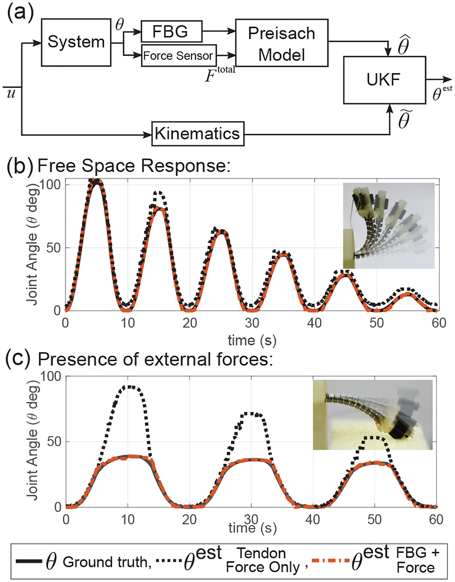
(a) UKF based observer for the meso-scale robot involves combining a kinematics model, tendon tension (f) and FBG fiber wavelength (Δλ) to generate joint angle estimate (θest), (b) Free space response of the observer, (c) Response of the observer in the presence of external tip forces.
V. Conclusions
In this work, we design and develop a sensor-framework using an FBG fiber to measure the shape of micro-scale and meso-scale continuum robots. To obtain strain in the core of the FBG while it bends, the neutral axis of the FBG fiber was shifted by attaching it within a UAN joint micromachined from a nitinol tube. One advantage of the sensor design is the ability to sense joint bending for small-scale joints, which we demonstrate using a micro-scale joint (OD = 0.41 mm) and a meso-scale joint (OD = 1.93 mm). The design and assembly process of this sensor are described for both scales of joints explicitly. Another advantage is a highly linear and repeatable response which can be explained by the analytical model proposed and validated in this work. One disadvantage of the sensor is a hysteresis pattern observed in the sensor response. However, this may be modeled effectively using a Preisach model. We demonstrate this using a Kalman Filter-based observer to estimate the deflection of the meso-scale joint. This sensor achieves, to the authors knowledge, the highest reported curvature of FBG bending sensors, 145 m−1. Future work will expand the unidirectional bending tested in this study to bidirectional bending applications, multi-joint sensing, and real-time control methods for the joints reported in this work in an MRI-safe environment.
Supplementary Material
Acknowledgments
This paper was recommended for publication by Editor Pietro Valdastri upon evaluation of the Associate Editor and Reviewers’ comments. Research reported in this publication was supported in part by the Children’s Healthcare of Atlanta and the GT/Emory Coulter Translational Research Partnership Program. Research reported in this publication was also supported in part by the National Heart, Lung, And Blood Institute of the National Institutes of Health under Award Number R01HL144714 and the National Science Foundation under Grant No. DGE-1650044. The content, opinions, findings, and conclusions or recommendations expressed in this material are solely the responsibility of the authors and does not necessarily represent the official views of the National Institutes of Health or the National Science Foundation.
Footnotes
Disclosure Statement: The development of the robotic guidewire and the robotic pediatric neuroendoscope are based on the steerable guidewire technology. Dr. Jaydev P. Desai and Mr. Yash Chitalia are co-inventors of the steerable guidewire technology and the intent is to commercialize it.
References
- [1].Vos T, Allen C, Arora M, Barber RM, Bhutta ZA, Brown A,Carter A, Casey DC, Charlson FJ, Chen AZ, et al. , “Global, regional, and national incidence, prevalence, and years lived with disability for 310 diseases and injuries, 1990–2015: a systematic analysis for the global burden of disease study 2015,” The Lancet, vol. 388, no. 10053, pp. 1545–1602, 2016. [DOI] [PMC free article] [PubMed] [Google Scholar]
- [2].Schneider P, Endovascular skills: guidewire and catheter skills for endovascular surgery, 3rd ed. CRC press, 2009. [Google Scholar]
- [3].Vatakencherry G, Gandhi R, and Molloy C, “Endovascular access for challenging anatomies in peripheral vascular interventions,” Techniques in vascular and interventional radiology, vol. 19, no. 2, pp. 113–122, 2016. [DOI] [PubMed] [Google Scholar]
- [4].Ali A, Plettenburg DH, and Breedveld P, “Steerable catheters in cardiology: Classifying steerability and assessing future challenges,” IEEE Transactions on Biomedical Engineering, vol. 63, no. 4, pp. 679–693, 2016. [DOI] [PubMed] [Google Scholar]
- [5].Haga Y, Mineta T, and Esashi M, “Active catheter, active guide wire and related sensor systems,” in Automation Congress, 2002 Proceedings of the 5th Biannual World, vol. 14 IEEE, 2002, pp. 291–296. [Google Scholar]
- [6].Mineta T, Mitsui T, Watanabe Y, Kobayashi S, Haga Y, and Esashi M, “An active guide wire with shape memory alloy bending actuator fabricated by room temperature process,” Sensors and Actuators A: Physical, vol. 97, pp. 632–637, 2002. [Google Scholar]
- [7].Clogenson H, Dankelman J, and van den Dobbelsteen J, “Steerable guidewire for magnetic resonance guided endovascular interventions,” Journal of Medical Devices, vol. 8, no. 2, p. 021002, 2014. [Google Scholar]
- [8].Clogenson H, Simonetto A, and van den Dobbelsteen J, “Design optimization of a deflectable guidewire,” Medical engineering & physics, vol. 37, no. 1, pp. 138–144, 2015. [DOI] [PubMed] [Google Scholar]
- [9].Chitalia Y, Wang X, and Desai JP, “Design, modeling and control of a 2-dof robotic guidewire,” in 2018 IEEE International Conference on Robotics and Automation (ICRA) IEEE, 2018, pp. 32–37. [Google Scholar]
- [10].Gaab MR, “Instrumentation: endoscopes and equipment,” World neurosurgery, vol. 79, no. 2, pp. S14–e11, 2013. [DOI] [PubMed] [Google Scholar]
- [11].Eastwood KW, Looi T, Naguib HE, and Drake JM, “Design optimization of neuroendoscopic continuum instruments for third ventriculostomy and tumor biopsy,” in Engineering in Medicine and Biology Society (EMBC), 2015 37th Annual International Conference of the IEEE IEEE, 2015, pp. 4853–4856. [DOI] [PubMed] [Google Scholar]
- [12].Gao Y, Takagi K, Kato T, Shono N, and Hata N, “Continuum robot with follow the leader motion for endoscopic third ventriculostomy and tumor biopsy,” IEEE Transactions on Biomedical Engineering, 2019. [DOI] [PMC free article] [PubMed] [Google Scholar]
- [13].Chitalia Y, Jeong S, Bok J, Nguyen V, Melkote S, Chern J, and Desai JP, “Towards the design and development of a pediatric neuroendoscope tool,” in Intelligent Robots and Systems (IROS), 2019 IEEE/RSJ International Conference on IEEE, 2019. (accepted). [Google Scholar]
- [14].Shi C, Luo X, Qi P, Li T, Song S, Najdovski Z, Fukuda T, and Ren H, “Shape sensing techniques for continuum robots in minimally invasive surgery: A survey,” IEEE Transactions on Biomedical Engineering, vol. 64, no. 8, pp. 1665–1678, 2017. [DOI] [PubMed] [Google Scholar]
- [15].Liu H, Farvardin A, Pedram SA, Iordachita I, Taylor RH, and Armand M, “Large deflection shape sensing of a continuum manipulator for minimally-invasive surgery,” in 2015 IEEE International Conference on Robotics and Automation (ICRA) IEEE, 2015, pp. 201–206. [DOI] [PMC free article] [PubMed] [Google Scholar]
- [16].Sefati S, Alambeigi F, Iordachita I, Armand M, and Murphy RJ, “Fbg-based large deflection shape sensing of a continuum manipulator: Manufacturing optimization,” in 2016 IEEE SENSORS. IEEE, 2016, pp. 1–3. [Google Scholar]
- [17].Sefati S, Murphy RJ, Alambeigi F, Pozin M, Iordachita I, Taylor RH, and Armand M, “Fbg-based control of a continuum manipulator interacting with obstacles,” in 2018 IEEE/RSJ International Conference on Intelligent Robots and Systems (IROS) IEEE, 2018, pp. 6477–6483. [Google Scholar]
- [18].Rahman N, Deaton NJ, Sheng J, Cheng SS, and Desai JP, “Modular fbg bending sensor for continuum neurosurgical robot,” IEEE Robotics and Automation Letters, vol. 4, no. 2, pp. 1424–1430, 2019. [DOI] [PMC free article] [PubMed] [Google Scholar]
- [19].Sheng J, Deaton NJ, and Desai JP, “A large-deflection fbg bending sensor for sma bending modules for steerable surgical robots,” in 2019 International Conference on Robotics and Automation (ICRA) IEEE, 2019, pp. 900–906. [Google Scholar]
- [20].Ryu SC and Dupont PE, “Fbg-based shape sensing tubes for continuum robots,” in 2014 IEEE International Conference on Robotics and Automation (ICRA) IEEE, 2014, pp. 3531–3537. [Google Scholar]
- [21].Roesthuis RJ, Kemp M, van den Dobbelsteen JJ, and Misra S, “Three-dimensional needle shape reconstruction using an array of fiber bragg grating sensors,” IEEE/ASME transactions on mechatronics, vol. 19, no. 4, pp. 1115–1126, 2013. [Google Scholar]
- [22].Araújo F, Ferreira L, Santos J, and Farahi F, “Temperature and strain insensitive bending measurements with d-type fibre bragg gratings,” Measurement Science and Technology, vol. 12, no. 7, p. 829, 2001. [Google Scholar]
- [23].Jelínek F, Arkenbout EA, Henselmans PW, Pessers R, and Breedveld P, “Classification of joints used in steerable instruments for minimally invasive surgery,” Journal of Medical Devices, vol. 8, no. 3, p. 030914, 2014. [Google Scholar]
- [24].Jelinek F, Arkenbout EA, Henselmans PW, Pessers R, and Breedveld P, “Classification of joints used in steerable instruments for minimally invasive surgerya review of the state of the art,” Journal of Medical Devices, vol. 9, no. 1, p. 010801, 2015. [Google Scholar]
- [25].York PA, Swaney PJ, Gilbert HB, and Webster RJ, “A wrist for needle-sized surgical robots,” in Robotics and Automation (ICRA), 2015 IEEE International Conference on IEEE, 2015, pp. 1776–1781. [DOI] [PMC free article] [PubMed] [Google Scholar]
- [26].Eastwood KW, Francis P, Azimian H, Swarup A, Looi T, Drake JM, and Naguib HE, “Design of a contact-aided compliant notched-tube joint for surgical manipulation in confined workspaces,” Journal of Mechanisms and Robotics, vol. 10, no. 1, p. 015001, 2018. [Google Scholar]
- [27].Gao A, Murphy RJ, Liu H, Iordachita II, and Armand M, “Mechanical model of dexterous continuum manipulators with compliant joints and tendon/external force interactions,” IEEE/ASME Transactions on Mechatronics, vol. 22, no. 1, pp. 465–475, 2017. [DOI] [PMC free article] [PubMed] [Google Scholar]
- [28].Jones JA, Lee Y-S, and Moore JZ, “Parametric study for asymmetric flexure hinge design for tissue cutting,” Proceedings of the Institution of Mechanical Engineers, Part B: Journal of Engineering Manufacture, p. 0954405418774587, 2018. [Google Scholar]
- [29].Mayergoyz ID, Mathematical models of hysteresis. Springer Science & Business Media, 2012. [Google Scholar]
- [30].Shirley ME and Venkataraman R, “On the identification of preisach measures,” in Smart Structures and Materials 2003: Modeling, Signal Processing, and Control, vol. 5049 International Society for Optics and Photonics, 2003, pp. 326–336. [Google Scholar]
- [31].Webster III RJ and Jones BA, “Design and kinematic modeling of constant curvature continuum robots: A review,” The International Journal of Robotics Research, vol. 29, no. 13, pp. 1661–1683, 2010. [Google Scholar]
Associated Data
This section collects any data citations, data availability statements, or supplementary materials included in this article.


