Highlights
-
•
CFD model validated for predicting pollutant dispersion around a HRR building.
-
•
Effects of distance and position angle of emission source studied.
-
•
Critical range of position angle of low risk found for pollutant source.
-
•
Pollutant concentration on building as a function of source location modelled.
-
•
Overall view of risk of pollutant emission from regions nearby building obtained.
Keywords: Pollutant dispersion, HRR building, CFD simulation, Pollutant source location
Abstract
This article investigates the dispersion of airborne pollutants emitted from different locations near a high-rise building. A Computational Fluid Dynamics (CFD) model for simulating the wind flow field and the pollutant dispersion was developed and validated by wind tunnel data. Then the spreading of the pollutant emitted from different locations to a rectangular-shaped high-rise residential (HRR) building was numerically studied. The pollutant source location was set in a wide range of the position angle and distance between the source and the building. It was found that the pollutant concentration on the building decreases with an increase in the emission distance whereas the effect of the position angle is more complicated. Interestingly, there is a critical range of the position angle from which the emitted pollutants will not spread to the building in a significant way. The effect of the source location was linked to the wind flow field around the building, particularly with several major flows. The vertical distributions of the pollutant concentration on different faces were also investigated, and it was found that these are more affected by the vertical flow near each face. Finally, a mathematical model was developed to evaluate the pollutant concentration as a function of the emission distance and position angle. These findings are helpful to the understanding of the dispersion of airborne pollutants around high-rise buildings and the related hazard management in urban design.
1. Introduction
Infectious bioaerosols, manifesting as airborne particles consisting of harmful biological materials, can be generated and emitted from different types of pollutant sources in urban areas. Once generated, they can spread to nearby buildings by the complicated wind flow in a not well-understood way. In the worst case, it can cause an outbreak of various respiratory and cardiovascular diseases, such as Severe Acute Respiratory Syndrome (SARS), bird flu, Legionella and Avian Influenza [1], [2], [3], [4], [5], [6]. Rising reports of such outbreaks have attracted scientific attention on understanding the spreading of airborne hazards in urban areas, which is helpful for the prediction and control of the outbreak of airborne diseases for public health [7], [8], [9], [10], [11].
The pollutant outbreaks are riskier near high-rise residential (HRR) buildings due to the high population density [12]. Additionally, the spreading of pollutants around and inside such buildings is more complex as a result of strong wind–structure interactions and diverse spreading scenarios. Pollutants may be emitted from an HRR building (e.g. from a kitchen exhaust) and spread to the same building at different positions [13,14], like the possible SARS spreading in typical HRR buildings in Hong Kong [15], [16], [17]. Pollutants may also be released from sources located around a HRR building at lower levels [18], [19], [20], [21], [22], such as the evaporative facilities (e.g. cooling tower or air scrubber) of public facilities, which have been responsible for reported disease outbreaks [23], [24], [25]. Accordingly, the position of the potential pollutant source is an important factor in evaluating the risk of the spreading of pollutants near an HRR building, but it has not been fully evaluated in terms of the distance and the position angle between the source and the building.
The spreading of pollutants in urban areas has been studied using various methods. Wind tunnel is a valuable tool in studying such pollutant dispersion under controllable wind flow and weather conditions [14,[26], [27], [28]. However, detailed information, such as the flow field, is difficult to obtain from wind tunnel experiments, even with the most advanced techniques such as Particle Image Velocimetry (PIV) [29]. Therefore, numerical models based on computational fluid dynamics (CFD) have been increasingly used to assist physical experimental studies. Such CFD models need to be carefully calibrated for specific problems, especially when considering the turbulence model and boundary conditions [30]. With the increasing of CFD studies in recent years, several efforts have been made to establish standard procedures for the accurate CFD simulation of the atmospheric boundary layer (ABL) in wind tunnels [31], [32], [33]. The choice of turbulence model in a CFD model normally needs to consider the balance between prediction accuracy and computational effort, which could be different for different problems investigated. It has been shown that Reynolds-Averaged Navier–Stokes (RANS) models are capable of predicting accurate pollutant dispersions in 2D and 3D urban models [34], [35], [36].
It has been shown that the combination of CFD and wind tunnel is effective in studying the detailed wind flow field and the spreading of pollutants, which is very helpful to the understanding of the micromechanisms of various controlling variables, such as the emission height, the re-entry of the building, the wind incident angle, the buoyancy effect, inter-unit dispersion, intake fraction and residential exposure [17,[37], [38], [39], [40], [41]. However, to the best of our knowledge, no comprehensive studies have been conducted on the effect of the pollutant source location on the spreading of pollutants to a nearby high-rise building. This paper contributes to filling this gap using a numerical model. The model was validated by good agreement with the measured data in a wind tunnel experiment on the pollutant dispersion around a high-rise building [28]. Then the model was used to investigate the spreading of pollutants from a wide range of emission locations around a building. From the numerical simulations, the pollutant concentrations on different faces and levels of the building were quantified and analyzed in connection with the wind flow field. The correlation between the pollutant concentration and the pollutant source location was studied. Based on that, a mathematical model was established, which can help assess the risk of pollutant dispersion from different regions around a building in an overall picture. These results are helpful in the planning and risk management of urban HRR buildings.
The rest of the paper is organized as follows. The studied building and environment and the corresponding CFD model are introduced in Sections 2.1 and Section 2.2, respectively, and the model validation is presented in Section 2.3. Then Section 3.1 analyses the simulated wind flow and pollutant dispersion to each building face in regards to pollutant source location, Section 3.2 further investigates the vertical distribution of the pollutant concentration on the building faces, and Section 3.3 proposes a mathematical model which facilitates an overview of the effect of pollutant location. Finally, Section 4 summarizes the findings and concludes the paper. The grid information and mesh independence analysis are described in the Appendix to avoid distracting the attention of the readers.
2. Model description
2.1. Geometry and simulation conditions
The physical model used in the model validation was based on a 1:30 scaled model of a 10-storey high-rise building 30 m in height, which is a typical HRR building in Hong Kong, and with a cruciform section and a so-called “re-entry” along each wing. Re-entry is a cul-de-sac design in order to accommodate a window/opening for all rooms to comply with the Hong Kong building code. Pollutant emission from an exhaust on the building was studied in a series of wind tunnel experiments [28]. The Reynolds number based on the building's height (ReUHH/ν) exceeds the suggested value of 15,000 to ensure that the measurements were independent of Re and the reduced-scale model can be reliably used [42]. The dimensions of the building model and wind properties were extracted from the boundary layer wind tunnel test and used for the validation of the numerical model. Additionally, a generic rectangular-shaped building was also modelled, which has the same outer profile as the cruciform-shaped building with the ratio between the height H, breadth B and depth D given by H:B:D = 1:0.98:1.04, as shown in Fig. 1 . Note the cruciform-shaped building model was used mainly for the validation of the numerical model as it was used in the wind tunnel experiment. The flow domain considered in the numerical model is illustrated in Fig. 2 . Although some guidelines recommend the maximum blockage ratio for wind tunnel modelling can be as high as 10% [32], a blockage ratio smaller than 3% is normally recommended for modelling the hypothetic open terrain [43] to prevent an artificial acceleration of the flow around the building, and there are recommendations for the blockage ratios at different faces [32,33]. Based on these acknowledged guidelines a cross-section with height of 6H and width of 11H was chosen for the computational domain as a hypothetical open terrain. Distances of 5H and 15H were assumed for the inlet and outlet from the building, respectively.
Fig. 1.
(a) Geometric models of the cruciform-shaped building and the rectangular-shaped building respectively; their dimensions both are H:B:D = 1:0.98:1.04; the cruciform-shaped building is a 1:30 scaled model of a HRR building in Hong Kong [28] . (b) Pollutant source locations around the building(s) based on the incident wind angle θ and emission distance r.
Fig. 2.
Computational domain and boundary conditions.
Researchers have conducted a series of numerical studies on the dispersion of pollutants released from a distance of 0.5H and H to an isolated building, located in the wake region [20,44,45]. This work considered a wider range of locations, which were not just in the wake region of a building. As shown in Fig. 1(b), the pollutant source was located at three circles of radii H, 1.5H and 2H around the center of the building respectively, and the position angle between the pollutant source and the building was set every 15° from 0° to 180° inclusive. Thus, in total 39 simulations at 13 position angles and 3 emission distances were conducted.
The computational domain was constructed in ANSYS/ICEM CFD software. The structured grids were placed in the computational domain to avoid numerical diffusion and promote more accurate convergence [46]. A grid size of 4.04 million hexahedron cells was chosen after the grid independence test, which is detailed in the Appendix. The smallest cell dimension was 4 mm × 4 mm × 4 mm in the three directions in the vicinity of the pollutant sources. The expansion ratio of 1.05 to 1.2 was used according to the need of each region, as recommended by guidelines that the expansion ratio should not be greater than 1.2 [32]. The fluid domain was divided into three regions as shown in Fig. 2. The first region, a cylindrical core around the building, aims to provide better resolution in the region near to the building. The second region, created in a doughnut shape, aims to cover the allocated locations for the pollutant source. This region was designed to avoid regenerating a new grid for any different position angles between the source and building. The third region was the rest of the domain. With the division into the different domains, the second part rotated every 15° from 0° to 180° counterclockwise to simulate the new pollutant source location.
The wind profiles of the atmospheric boundary layer generated in the wind tunnel test were imposed as a velocity inlet boundary condition using User Defined Functions (UDF) in ANSYS Fluent solver. The wind velocity and turbulent intensity profiles measured in the wind tunnel experiment are shown in Fig. 3 . Both power law and logarithmic law are commonly used to describe the wind velocity profile as a function of height [33,47,48]. Here we adopted logarithmic law as shown in Eq. (1) to accommodate the wind velocity profile in the wind tunnel experiment. Then the friction velocity (u *) can be calibrated for the turbulent dissipation rate ε(z) (Eq. (2)) and turbulence parameter C μ, and the calibration procedure will be explained in detail later [33]. κ is the von Karman constant (0.42) and z 0 corresponds to the aerodynamic roughness length of (0.02/30 m) of the wind profile in the wind tunnel which simulated open terrain (Category 2) in the Australian Standards. The kinetic energy of turbulence was calculated from the wind velocity, U(z), and turbulent intensity profile, I(z) (Eq. (3)), and imposed to the inlet boundary condition as well as the wind velocity and dissipation rate profile.
| (1) |
| (2) |
| (3) |
Fig. 3.
Comparison of (a) Mean velocity and (b) Turbulent intensity profiles imposed at the inlet (x= −5 H) and obtained from the simulations near the outlet (x = 14 H). Circles are the approaching wind profiles obtained from the wind tunnel experiment [28], which were also the inlet boundary conditions used in simulations. The simulated profiles near the outlet were obtained with different models: yellow dashed lines were obtained with the standard k–ε model with the presence of the cubic building; blue solid lines and dotted lines were results obtained with the improved k–ε model with the presence of the cubic and cruciform buildings respectively. (For interpretation of the references to colour in this figure legend, the reader is referred to the web version of this article.)
The standard wall functions proposed by Launder and Spalding [49] were used in this study. Sand-grain roughness height kS is defined as a function of aerodynamic roughness length, y 0, and the roughness constant, CS, as shown in Eq. (4) [31].
| (4) |
As the value of kS should be smaller than zP, which is the distance from the centre point of the ground adjacent cell and ground, the height of the first layer of (structured) cells to the ground, and the roughness parameters, kS and CS, were set in a way to satisfy this condition. For the building's surfaces kS was set to zero. Using standard wall function, each wall-adjacent cell's centroid should be located in the logarithmic layer and the near wall y+ should range between 30 and 300. The y+ value in the vicinity of the domain ground and building faces are all between 30 and 45.
Other boundary conditions were considered as follows: the slip wall condition was imposed at the top boundary and lateral boundaries (zero normal velocity and zero normal gradients of all variables) and zero static pressure at the outlet boundary (Fig. 2). Concerning the boundary condition for the pollutant source, 10% of propane with a flow rate of 58.5 ml/s was allocated to the surface of the pollutant source following the wind tunnel test [28]. As the difference between the density of mixed gas and ambient air is less than 5 percent, the buoyancy effect is negligible. Note that this experiment was deliberately designed to reproduce the comparable situation for the pollutant dispersion in Hong Kong city, and it has been effectively used for the calibration and validation of the corresponding numerical wind tunnel model in a series of studies [28,50,51].
2.2. Governing equations and numerical schemes
The selection of an appropriate turbulence model is linked to the level of detail of the considered geometry, the grid size and the discretization schemes [29]. Although the Large Eddy Simulation (LES) is known to be a more accurate model than the RANS approaches in predicting the flow and pollutant dispersion in urban simulations [52,53], there are still challenges with LES applications including the much higher computational cost, the development of advanced sub-grid scale models and the difficulty in specifying appropriate time-dependent inlet boundary conditions [39,54]. In spite of the RANS models' limitations, they have been successfully validated and widely adopted in predicting the mean airflows and pollutant dispersion in urban models [20,38,39,54,55].
One important step for the calibration of the numerical model is to achieve horizontal homogeneity for the wind profile through the tunnel. Traditionally, this is fulfilled by using the vertical wind profile measured in the empty wind tunnel as the inlet boundary condition and comparing it to the simulated incident profile at the target location in the empty numerical domain, and the two profiles should be in good agreement with each other. However, it could be more complicated with the presence of building(s). Therefore, a remedy is recommended to improve the turbulence model utilizing specified source terms in the transport equations of k or ε [56,57] and implement Non-Linear Eddy Viscosity models (NLEV) for the disturbed flow within the Building Influence Area (BIA) [58]. To realize this remedy, we implemented the method proposed by Parente et al. [56] by including a source term in ε transport equation and treating C μ differently for disturbed and undisturbed flows.
Firstly, the following source term is added to the ε transport equation to simulate atmospheric features that the standard k–ε model is typically not able to reproduce:
| (5) |
This source term added to the dissipation rate equation to maintain the value of the turbulent dissipation Prandtl number (σε) [59]. Secondly, C μ is considered as a function of k for the undisturbed flow in the ABL according to [60], given by:
| (6) |
In the BIA, according to one of the latest Parente's studies [58], C μ is best described by the equation proposed by Ehrhard and Moussiopoulos [61], given by:
| (7) |
where S and Ω are the strain rate and vorticity invariants, respectively. The proposed relation between the strain rate and vorticity behaves much better than an ordinary eddy viscosity model [58,62].
Following the related studies [58,59,62], here the BIA is an automatically detected region where the turbulence parameters are gradually blended from the formulations for the undisturbed ABL to the ones more suitable for the disturbed BIA to avoid any abrupt transition. To attain this goal, the so-called Hybrid Blending, based on the deviation of local velocity and kinetic energy with respect to the undisturbed ABL, is adopted with the blending metric, δh, given by:
| (8) |
Then, the following formulation is used for the transition between the different flow areas (namely BIA and ABL):
| (9) |
where ϕ represents C μ, μt (μt = ρC μ k 2/ε) or S ε.
An Eulerian approach was utilized to compute the pollutant dispersion in the fluid domain. This approach treats the pollutants as a continuum phase and assumes that the effects of pollutant inertia are negligible. In this approach, the turbulent and steady form of the scalar transport equation governing the convective–diffusive motion of pollutants is given by:
| (10) |
where ci is the local pollutant mass fraction, D i,m is the mass diffusion coefficient of the pollutant in the mixture, Dt is turbulent diffusion coefficient (where Dt = μt/ρSct for Sct = 0.7) and Si denotes the pollutant source term.
The simulations were performed by the commercial CFD code Fluent 18.1 which is based on a finite volume method. The “SIMPLE” algorithm was employed to solve pressure–velocity coupling and the second order differencing scheme was applied for convective terms and viscous terms in governing equations, including momentum, k and ε, and pollutant concentration. When the scaled residuals reached below 10−6, the solution was regarded as converged.
2.3. Model validation in terms of wind flow and concentration fields
The experimental study was performed in a turbulent boundary layer wind tunnel at the Hong Kong University of Technology. Wind tunnel parameters and details of conducted experiments can be found in the reference [28]. The numerical model, with the mentioned boundary conditions in the previous section, generated a turbulent boundary layer flow. Using the wind velocity (3.27 m/s) at the building height (1 m), the friction velocity, u * ≈ 0.188 m/s, was obtained from Eq. (1) and applied to give the turbulent dissipation rate at the inlet boundary condition. The measured wind profiles (wind velocity and turbulent intensity) at the position of the building in the empty wind tunnel experiments were used as the inlet boundary condition in the numerical model. The atmospheric boundary layer should be horizontally homogenous both upstream and downstream of the domain [31], which means that the flow characteristics in different sections along the wind stream should agree with each other. This is a critical part of establishing a valid computational model and it was achieved through calibrating the wall functions and the boundary layer mesh together. The standard k−ε model was improved by using User Defined Functions (UDF) in FLUENT to adjust the wall function parameters (kS and z 0) simultaneously and employing the improved turbulence model within and outside of the BIA, a set of parameters was finally determined to satisfy the agreement between the simulated wind profile and experimental data, in terms of both velocity and turbulent intensity. In Fig. 3 the experimental wind profiles utilized at the domain's inlet (x = −5H) as boundary condition are compared with the simulated ones in the downstream part of the domain (x = 14H) near the outlet of the numerical domain for both cubic and cruciform shaped buildings. It can be seen that the improved k–ε model predicted much better results than the standard k–ε in order to replicate homogenous ABL flow along the wind stream.
The next validation was for the pollutant dispersion. In the experimental study [28], air with 99,000 ppm (10%) propane was released with a flow rate of 58.5 ml/s from the locations within the re-entry on different floors, as shown in red in Fig. 1. The same conditions were set in the numerical model, and the simulated pollutant concentrations on different floors were compared to the experimental data [28] and previous numerical simulations [17,50]. Fig. 4 (a) and (b) show normalized pollutant concentrations for windward and leeward emissions respectively, in terms of the commonly used normalized concentration KC, given by [19,28,50]:
| (11) |
where C is the mean pollutant concentration, UH is the wind speed at the building model height (H), S are the areas of the windward, side and leeward faces which can be approximated by H 2 for our studied building with nearly uniform dimensions, and Q is the volumetric flow rate of emitted pollutant. The measured normalized concentration in Fig. 4 is area weighted average on the surface of the building in the same re-entry in which pollutant is emitted.
Fig. 4.
Normalized concentration distribution within the re-entry for (a) windward emission and (b) leeward emission for the cruciform-shaped building model in the wind tunnel experiment.
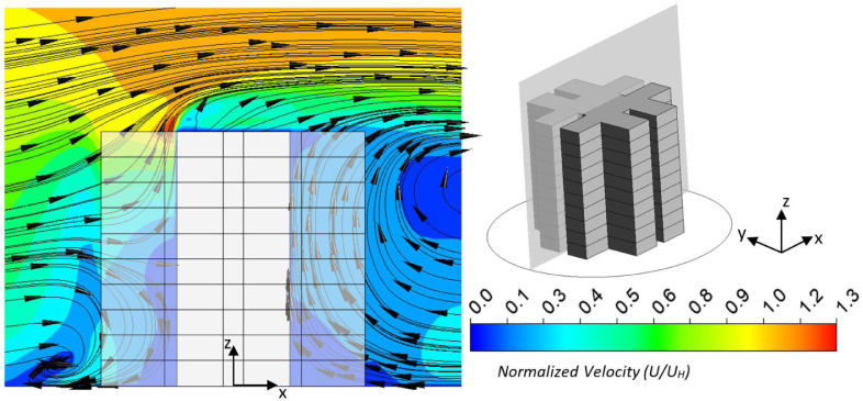
Fig. 4 shows that the predicted KC as a function of the floor level was in good quantitative agreement with the experimental results and previous CFD simulations. In particular, the features of the migrating pollutants resulting from the wind flow were captured. For example, in Fig. 5 (a), the simulated flow shows a stagnation point on the 6th floor of the building's windward face in the re-entry. Thus, Fig. 4(a-1) shows that KC was higher in the first three floors when the emission point was located below the stagnation point on the 3rd level in the re-entry, and the pollutant pathway was mainly downward. However, when the source was on the 6th floor, KC decreased with the vertical distance from the source and increased in both the upward and downward directions, as shown in Fig. 4(a-2). This was due to the downwash and upwash effects happening near the releasing point pushing the pollutant vertically in both directions. If the pollutant was emitted from the 9th floor, following the flow streamlines it would mainly travel upwards, affecting the higher levels and passing over the top of the building. As a result, as illustrated in Fig. 4(a-3), the concentrations on the 9th and 10th floors were high, while those on the lower levels were almost negligible.
Fig. 5.
Simulated flow pattern near the windward and leeward sides of the cruciform-shaped building model. Left figure is the cross section view, and the section is shown in the 3D view in the right figure.
For the leeward emission, Fig. 4(b) indicates that the pollutant concentration was generally higher along the re-entry on the floors above the emission level, with a sudden drop below the emission point in all three cases. This pollutant distribution pattern was linked with the air flow pattern at the lee of the building. Fig. 5 shows that the airflow on the leeward side of the building in the re-entry was primarily vertically upward and created a turbulent recirculation at the lee of the building, which carried the pollutant to the upper 3rd, 6th and 9th floors as shown in Fig 4(b-1), (b-2) and (b-3), respectively. If the pollutant is entrapped in the recirculation bubble downstream of the building, it may come back to the building and impinge in the re-entry; otherwise it will migrate with the downstream airflow towards the exit of the fluid domain.
The above comparison demonstrated the validity of the numerical model. However, the cruciform shape of the building used in the model validation complicates the effect of wind–structure interaction in this study as discussed in our previous studies [17,50]. Therefore, in the following discussion, mainly the generic rectangular-shaped building was used in the simulation and the study was focused on the spreading of the pollutant emitted from different source locations around the building.
3. Results and discussion
To investigate the effect of the pollutant source location, three different emission distances around the building at every 15° were examined, as detailed in the model description. At each considered location, a simulation using the generic rectangular-shaped building was conducted, and the simulated pollutant concentration distributions were analyzed. As depicted in Fig. 1, the pollutant source location was defined by the position angle, θ, and the emission distance, r, between the pollutant source and the center of the building. The effects of θ and r on the distribution of KC on different faces and levels of the rectangular-shaped building, as a generic model, were analyzed, and a mathematical model was proposed at the end of the section.
3.1. Effect of position angle and emission distance on concentration distribution of pollutant on building's faces
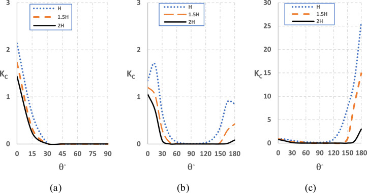
Fig. 6 shows the normalized pollutant concentration on the windward, side and leeward faces of the building as a function of θ with different emission distances. As illustrated in Fig. 6(a), for the windward face, KC was the highest at θ = 0°, then decreased rapidly to almost zero as θ increased to approximately 30°. With the increase of r, the maximum KC at θ = 0° decreased. For the side face, as shown in Fig 6(b), KC had two peaks at a θ ≈ 0° and θ ≈ 180°, whereas the location of the first peak moved to a higher value and that of the second to a lower value with the decrease of r. On the other hand, KC was very small between two critical angles [θ1, θ2], while the values of θ1 and θ2 were dependent on r. As depicted in Fig 6(c), KC on the leeward face also had two peaks near θ ≈ 0° and θ ≈ 180°, respectively. However, the first peak was rather low while the second peak very high. Also, similar to the side face, there was a range of angle between two critical values [θ1, θ2], in which KC was very small. The critical angles were different from those for the side face, and they were also dependent on r. Generally, Kc on the leeward face was much higher than on other faces when θ was close to 180°.
Fig. 6.
Profiles of normalized pollutant concentration on (a) windward, (b) side and (c) leeward of the building emitted from a pollutant source located in different distances (H, 1.5H and 2H) and different angle ([0°, 180°]). Note that the scale of Kc is different in different subfigures.
It can be seen that KC approached zero in the interval of θ bounded by two critical values of θ1 and θ2. As the two angles are different for different faces and emission distances, conservatively the intersection set of these intervals is a relatively safe region for the location of facilities which are potential pollutant sources. In other words, if the pollutant outbreaks in such a region, KC on all faces of the building will always be very small; whereas if the outbreak occurs out of this region, the building will be significantly attacked on at least one of its faces. Note here only half of the region was considered while the other half was supposed to be symmetric.
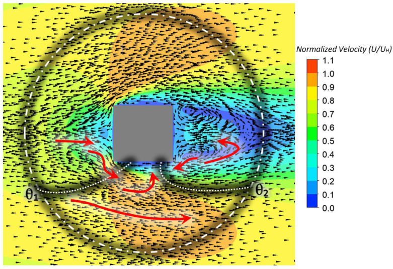
The three regions: [0°, θ1], [θ1, θ2] and [θ2,180°] are closely linked to the wind–structure interaction, as shown schematically in Fig. 7 . If the pollutant spreads out from the first region (θ∈ [0°, θ1]), it will mainly affect the windward face of the building as the air mainly flows to the windward face. However, since the air will flow over the side face with the separation reattachment, a certain amount of the pollutant may be carried to and deposit on the side face. The remainder of the pollutant not depositing on either the windward or the side face is carried to the lee of the building and may be dragged to the leeward face due to the recirculation flow there. The amount of the pollutant to be carried to the side and leeward faces is dependent on how close the pollutant source is to the building. If the pollutant enters the side region through a closer location to the building, it will more likely pollute the side face. Also, if the pollutant carried by the wind flow exits closer to the side of the building and enter the lee, it is more likely to be trapped in the wake at the lee of the building. Consequently, θ1 decreases and the interval of [θ1, θ2] narrows as r increases.
Fig. 7.
Top view of the wind velocity field on a section passing through the middle of the building (z = 0.5H). Red arrows are illustrating the different flows; θ1 and θ2 are schematics of the critical ranges discussed in the text. (For interpretation of the references to colour in this figure legend, the reader is referred to the web version of this article.)
When the pollutant source is located in the third region (θ∈ [θ2,180°]), pollutant will be released inside or close to the recirculation zone at the lee of the building. Hence the pollutant can be dragged to the leeward face or even to the side face. As the pollutant source is closer to the building and the center of the recirculation zone (θ = 180°), the likelihood of pollutant becoming trapped in the wake at the lee of the building increases. Accordingly, θ2 gets closer to 180° and the interval of [θ1, θ2] narrows as r increases.
When the pollutant source is located in the second region (θ∈ [θ1, θ2]), the pollutant is carried by the wind flow without any deposition on the side face of the building as the emission point is not sufficiently close to the building. The pollutant carried to the leeward region also does not enter the recirculation flow, so it travels to the downstream part of the domain without any deposition on the leeward face of the building.
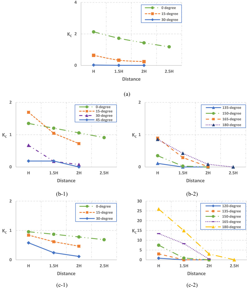
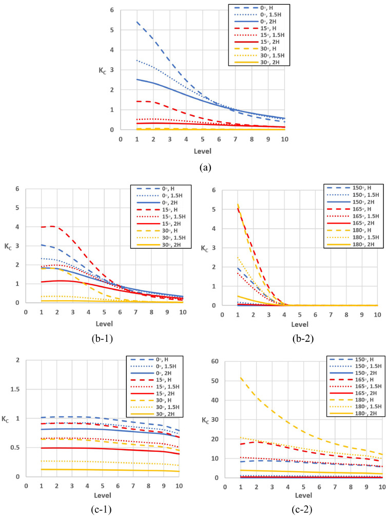
The effect of r on the pollutant concentration on different faces of the building is shown in Fig. 8 . Here some typical position angles were used, according to the regions identified in Fig. 7. Generally, it can be seen that KC decreased with r at any angle and for any face of the building and approaches almost zero at certain large r. When the pollutant was released from the first region (θ∈ [0°, θ1]), the pollutant concentration decreased smoothly with an increase of r on all the faces, as shown in Fig. 8(a), (b-1) and (c-1). However, KC was strongly dependent on the combination of r and θ when the pollutant source location was in the third region (θ∈ [θ2,180°]), as shown in Fig. 8(b-2) and (c-2). Such complicated combined effects of r and θ are due to the recirculating bubbles formed on the vertical and horizontal planes in this region, as shown in Fig. 9 . When the pollutant source is situated closer to the center of the bubble and closer to the building, there is more possibility for the pollutant to spread to the building before returning to downstream part of the flow field. Two additional cases at the emission distance of 2.5H and position angles of 0° and 180° were further considered and included in the figure. It is shown that for a larger r, if the pollutant was emitted from θ = 0°, KC still decreased smoothly with the increase of r; but if the pollutant was emitted from outside of the recirculation bubble (θ =180°), Kc on the side face (Fig. 8(b-2)) and leeward face (Fig. 8(b-c)) approached almost zero as the pollutant cannot be returned back to building by the recirculation flow. This highlights the importance of the pollutant source location on the pollutant spreading, in particular not only the distance but also the position angle, as the wind flow field will be very different near different building faces.
Fig. 8.
Normalized pollutant concentration on the (a) windward, (b) side and (c) leeward faces of the building as a function of emission distance with different position angles.
Fig. 9.
Recirculating bubbles which extend far downstream in (a) vertical and (b) horizontal plane.
3.2. Effect of position angle and emission distance on concentration distribution on building's levels
For a high-rise building, the distribution of the pollutant can vary greatly on different levels [17,50]. Therefore, the pollutant concentration on each level was also studied. Note that here only the releases from the first and third regions were considered here, as the overall concentration was very low for the release in the second region. KC presented here is the area-weighted average of normalized concentration over the surface of level 1 to 10 depicted in Fig. 1(a) for the generic building.
As shown previously, the windward face of the building is mainly affected by the emission from the first region (θ∈ [0°, θ1]). Fig. 10 (a) shows the distribution of KC on the windward face of the building when the source is located in this region, which can be related to the stagnation point of the flow on this face. Generally, the highest KC was found on the 1st level, and Kc decreased with the increase of the level. Note as θ1 is dependent on r, so if θ = 15° or 30°, the pollutant affected the windward levels when r = H but it had very small effect when r ≥ 2H or r ≥ 1.5H, respectively.
Fig. 10.
Normalized pollutant concentration at the different levels of (a) windward, (b) side and (c) leeward faces, respectively.
Fig. 10(b) shows that the pollutant accumulated more on the first two levels of the side face when it was emitted from θ ∈ [0°, θ1]. As the level increased, KC decreased gradually, similar to that of the windward face. On the other hand, when the pollutant source was located in θ ∈ [θ2,180°], a fraction of the pollutant deposited on the first four levels of the side face but did not reach to the higher levels.
As depicted in Fig. 10(c), when the pollutant source location was in the first region ([0°, θ1]), KC distributed uniformly on the levels of the leeward face regardless of the pollutant source location. When the pollutant source was located in θ ∈ [θ2,180°], the pollutant deposited on all levels of the leeward face much more than the other faces of the building, especially on the lower levels.
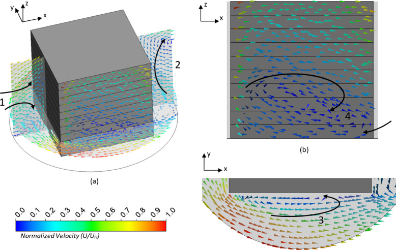
The KC distribution on different levels is closely related to the vertical flow near each face of the building, which is shown in Fig. 11 . Near the windward face of the building, there were strong downwash and upwash flows divided at the stagnation point as shown as arrow 1 in Fig. 11(a). The recirculating bubble near the leeward face, shown as arrow 2 also in Fig. 11(a), generated an upwash flow vertically along the building. Near the side face, the flow was mainly lateral but not vertical as shown in Fig. 11(b). However, the separation reattachment along the windward corner and the side face, as shown as arrow 3 in Fig. 11(c), retained the pollutant on the side face.
Fig. 11.
Flow fields around the side face of the building governing the vertical distribution of the pollutant on the side face: (a) 3D view; (b) the vertical plane near the side face showing in (a); (c) the horizontal plane at the height of the first floor showing in (a).
The downwash airflow near the windward face is responsible for the highest KC on the first level of the windward face, but this only applies to the pollutant emitted from the first region, as shown in Fig. 10(a). On the leeward face, when the pollutant was emitted from θ ∈ [0°, θ1], a small amount was carried to the lee of the building by the lateral flow and KC distributed evenly on the levels of the leeward face due to the vertical flow in the recirculation bubble as shown in Fig. 10(c-1). Such a vertical flow is more effective when the pollutant is emitted from θ ∈ [θ2, 180°].
The vertical flow near the side face is more complicated than those of the other two faces. There was no major vertical flow; however, the collisions of different flows generated local vertical flow. In particular, the lateral flow next to this face was affected by the upstream airflow coming from the windward region and the downstream airflow returning by the recirculation bubble from the lee of the building, which created local vertical flow only near the first level, as shown as arrow 4 in Fig. 11(b). Hence, under the combined effects of the local vertical flow and separation reattachment, the pollutant emitted from θ ∈ [0°, θ1] deposited more on the first to third levels of the side face, as shown in Fig. 10(b-1), whereas for the pollutant emitted from θ ∈ [θ2, 180°] a small fraction was returned to the side face by the recirculating flow and accumulated on the first level due to the local vertical flow, as shown in Fig. 10(b-2).
3.3. Mathematical model
In the literature, there are mathematical models to predict the plume dispersion depending on emission properties and wind characteristics, such as Gaussian dispersion models [63]. In these models, a plume is discharged from the rooftop of a building or isolated emission stack and the resulting pollutant concentration at a certain distance in the downstream can be evaluated. However, there are no models that can consider the pollutant dispersion to a building if the emission location is not exactly upstream of the building, or can take the dispersion to different faces into account.
Here based on our comprehensive simulation data, a mathematical model for normalized pollutant concentration as a function of the pollutant source location was proposed. This model aims to provide a general and overall picture of the dispersion of the pollutant to a high-rise building from its nearby region. The normalized pollutant concentration (KC) on the simulated rectangular-shaped building as a function of the emission position angle (θ) and emission distance (r) between pollutant source and building can be estimated by Eqs. (12), (13) and (14) for the windward, side and leeward faces respectively for the simulated cases. The value of R-squared between the predicted results and the simulated data in this study is above 0.96.
| (12) |
| (13) |
| (14) |
where θ∈ [0, π].
Interestingly, all the equations include one or two terms of the general form of , which indicates that generally, KC is in an inverse parabolic relationship with r and an exponential relationship with θ. As discussed in Sections 3.1 and 3.2, the pollutant concentration on the windward face is mainly affected by the downwash flow near the windward face of the building, therefore Eq. (12) contains one of these terms. On the other hand, the pollutant concentrations on the side and leeward faces are mainly controlled by the lateral flow in the side region and the recirculating flow in the leeward region, hence KC is more effectively modelled as a superposition of two such terms in Eqs. (13) and (14), and shows two relative maximum points. These maximum points decrease with the increase of emission distance and approach to zero after certain distances. Note this model is a basic one to consider the effect of the emission source location, which can be improved to include other factors.
Further, to investigate the generality of the mathematical model, 39 scenarios with the same wind flow conditions for different pollutant source locations were simulated for the cruciform-shaped building. It is found that a similar mathematical model can also be proposed for this complicated building. KC distributions on the windward, side and leeward faces as a function of the emission location (r & θ) can be given by Eqs. (15), (16) and (17), respectively. The R-squared between the predicted results and simulation data is above 0.95. These three equations are in the same forms as Eqs. (12), (13) and (14), respectively, but the coefficients are different. This indicates the terms could be general in describing the effect of the emission location on the pollutant dispersion to a nearby building.
| (15) |
| (16) |
| (17) |
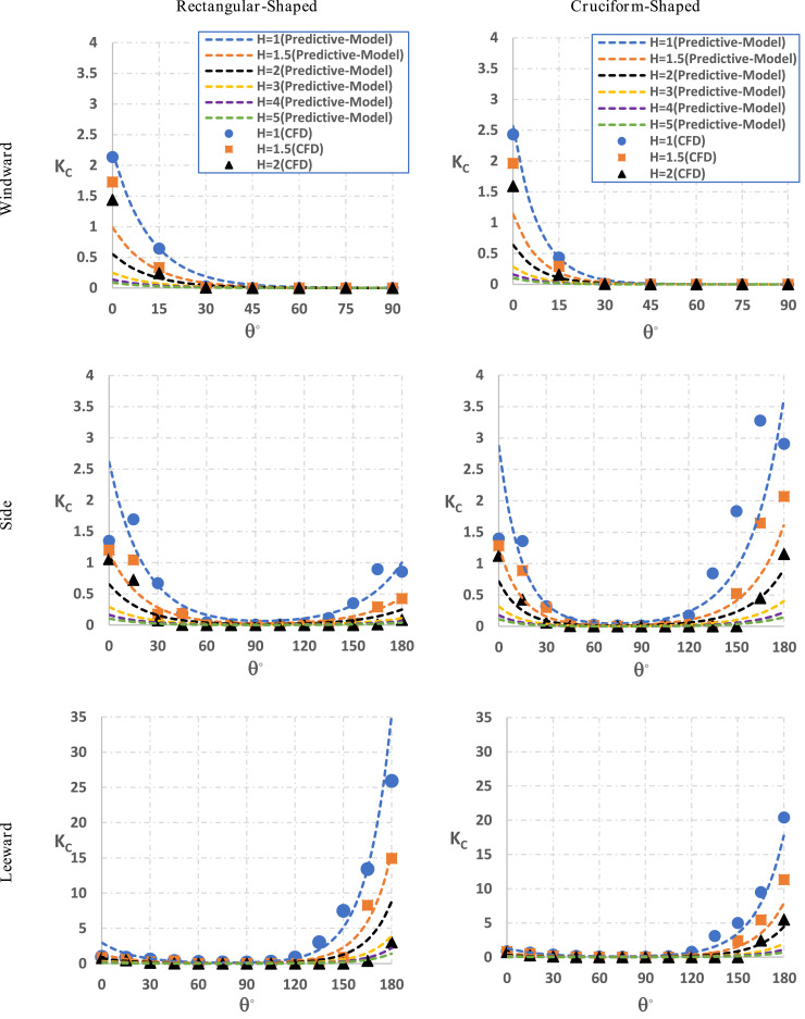
Fig. 12 illustrates KC on different faces of the two buildings concluded from the CFD simulations and the proposed mathematical models. Firstly, the comparison between the CFD simulation and the mathematical model shows good agreement for the comprehensive range of the emission position. Secondly, the capability of such models for buildings with more complicated shapes is also illustrated by the example of the cruciform-shaped building. The mathematical models can also help to determine the critical angles θ1 and θ2 and thus a relatively safe zone around a HRR building. Note dimensionless parameters are used in the model; therefore the model includes the building height, wind speed and emission rate as can be seen in (Eq. (11)). Hence the generality of the model can be studied by varying these variables in the future.
Fig. 12.
Profiles of normalized pollutant concentration on the faces of the rectangular-shaped and cruciform-shaped buildings emitted from different pollutant source locations.
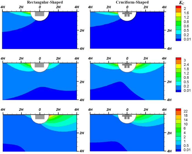
As calculated by the mathematical equations, KC on different faces of the buildings as a function of the emission position is shown in Fig. 13 . Note that the value of KC at each point does not represent the pollutant concentration of that point but shows the normalized pollutant concentration on a building face when the pollutant source is located at the point. Such figures provide a direct visualization of the emission region that can generate certain pollutant concentration on a building face, which can be helpful for the related hazard management. For example, if KC > 0.01 is set as the unsafe threshold, the blue regions in the figures can be regarded as the safe regions for the pollutant emission source. The figures can also be used to directly compare the effect of the building shape on the pollutant dispersion. As shown here, the blue regions (KC < 0.01) are similar for the windward and leeward faces of the two buildings, but different for the side face. These regions result from the complicated interactions among the wind, building and pollutant, which are more easily assessed in such overall views.
Fig. 13.
Contours of normalized pollutant concentration on (a) windward, (b) side and (c) leeward face of rectangular and cruciform sectioned buildings as a function of the emission location.
4. Conclusions
A CFD model to simulate the wind flow and pollutant dispersion near a high-rise building was developed and validated by good agreement with wind tunnel experiments in terms of wind profiles and pollutant concentration distribution. Then the effect of the pollutant source location on the pollutant dispersion to a rectangular building was numerically studied. The normalized pollutant concentration KC as functions of the emission distance r and the emission position angle θ were quantified and analyzed. The following major conclusions can be drawn based on the results:
-
(1)
Generally, KC on the building decreases with an increase in r. However, its behaviour is more complicated with the combination of r and θ. In particular, KC was the highest on the windward face when θ was near to 0° and decreased sharply with the increase of θ. On the side and leeward faces, Kc peaked at both θ ≈ 0° and θ ≈ 180°. These features are closely related to the wind flow field near the building. The highest Kc was found on the leeward face when the emission location was at the lee of the building, resulting from the significant recirculation flow there.
-
(2)
Two critical values of θ define three regions around the building ([0°, θ 1], [θ 1 , θ 2] and [θ 1 ,180°]). KC on the building is significant only when the pollutant source is located in the first and third regions. These regions are dependent on r and different for different faces. In the studied cases, a sector-shaped region around the building can be identified, in which the pollutant emission does not have a significant effect on the building.
-
(3)
In general, pollutant emitted from ground level accumulates on the lower levels of a high-rise building and decreases with increase of height. But at different faces, the vertical distributions of Kc will be affected by different vertical flows near the faces.
-
(4)
Based on the simulated data, a mathematical model was developed to estimate the overall pollutant concentration on a building face with the pollutant emitted from different locations. The mathematical model shows Kc can be modelled as the superposition of one or two terms in the form of .Similar mathematical models can also be applicable to the cruciform-shaped building. The mathematical model can give a quantitative overview of the effect of the emission location.
This work shows that CFD simulations combined with wind tunnel experiments are a cost-effective way to conduct comprehensive studies on pollutant dispersion in urban areas. With well-designed and controlled numerical simulations, the generated numerical data can be used to establish mathematical models for estimating the pollutant dispersion under given conditions. The results will help understand the spreading of airborne pollutants around high-rise buildings and the related hazard management in urban design.
Acknowledgments
The authors are grateful for the financial support from Australian Research Council (IH140100035) and the international PhD scholarships from Western Sydney University.
Footnotes
This article belongs to the Special Issue: CFD2018 Melbourne: Selected papers from the 13th International Conference on CFD in the Minerals and Process Industries.
Appendix
Grid Convergence
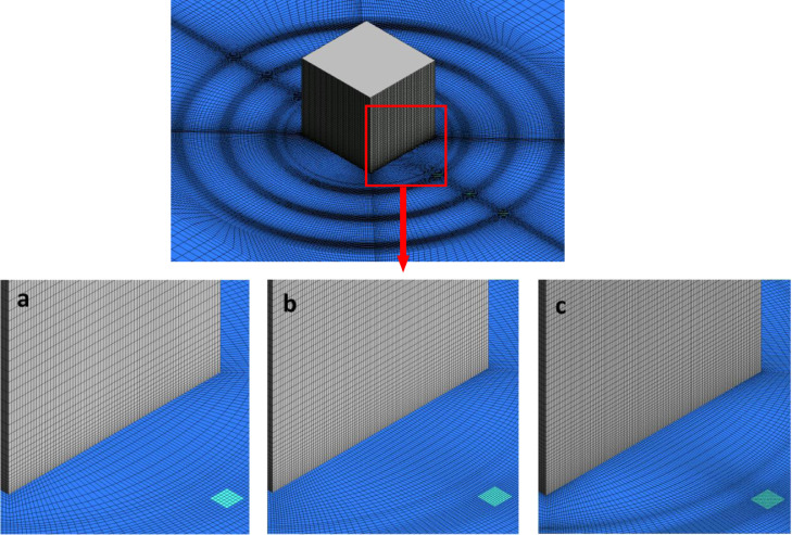
Three grids with approximate numbers of 2.6 million (coarse), 4 million (basic) and 7.7 million (fine) were constructed by refining and coarsening the basic grid. The height of the first mesh layer was set to 4 mm to satisfy the standard wall function with the same roughness parameters (kS&CS) for each grid. Using a UDF, a value of 3.5 was set for CS in order to satisfy kS < zp. The three grids are illustrated in Fig. A1 . For the three grids, the expansion ratios were all within 1 to 1.2 and the near wall y+ within 30 to 300, which met the recommendations in the guidelines [32,64]. A grid sensitivity study was conducted for the normalized streamwise wind speed and turbulent kinetic energy on a vertical line at the distance of 0.25H from the lee of the building which is the most critical region due to the recirculation flow. The Grid Convergence Index (GCI) proposed by Roache [65,66] was adopted in order to estimate the grid induced discretization error. For three-dimensional calculations, the grid refinement factors are r 21 = N 1/N 2 and r 32 = N 2/N 3 where N is the total number of cells for the coarse (N 3), medium (N 2) and fine (N 1) grids. Using the fixed-point iteration method, the apparent order p can be calculated as follows:
| (A-1) |
| (A-2) |
| (A-3) |
where ε32 = φ3 − φ2 and ε21 = φ2 − φ1, being φi the variable value on the ith grid. Using FS=1.25 as the factor of safety coefficient and as the extrapolated relative error in obtaining variable φ, the GCIs can be calculated by:
| (A-4) |
Fig. A1.
Perspective view of grids for grid-sensitivity analysis: (a) Coarse grid; (b) Medium grid (reference grid); (c) Fine grid.
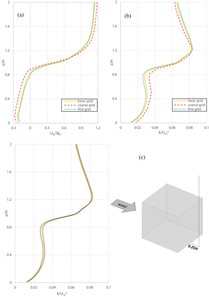
GCI estimations are carried out for the normalized wind speed and kinetic energy along the vertical line, obtaining values comprised 0–5.8%. As representative results, 0.18% and 3.1% are found for UX/UH and k/UH 2 at z/H = 0.5, respectively.
Fig. A2 (a) and (b) show the normalized streamwise wind speed and turbulent kinetic energy, respectively, along the vertical line. Fig. A2(c) shows the 1.25 × band of GCI for the basic grid solution. The grid–induced error band confirms the grid sensitivity is most pronounced for the lower heights. Nevertheless, based on these relatively small differences, the basic grid was utilized for further analysis in this study.
Fig. A2.
Grid sensitivity for three grids along a vertical line at the lee of the building: (a) Vertical profile of normalized streamwise wind speed; (b) Vertical profile of turbulent kinetic energy; (c) Results of turbulent kinetic energy on the basic grid with the indication of 1.25 × GCI.
References
- 1.Zhang D.-D., Zhong H.-Y., Liu D., Zhao F.-Y., Li Y., Wang H.-Q. Multi-objective-oriented removal of airborne pollutants from a slot-ventilated enclosure subjected to mechanical and multi component buoyancy flows. Appl. Math. Model. 2018;60:333–353. [Google Scholar]
- 2.Wéry N. Bioaerosols from composting facilities—a review. Front. Cell Infect. Microbiol. 2014;4:1–9. doi: 10.3389/fcimb.2014.00042. [DOI] [PMC free article] [PubMed] [Google Scholar]
- 3.Keshavarzian E., Ghalati P.F., Abouali O., Ahmadi G., Bagheri M.H. Proceedings of the ASME Fluids Engineering Division Summer Meeting collocated with the ASME 2012 Heat Transfer Summer Conference and the ASME 2012 10th International Conference on Nanochannels, Microchannels, and Minichannels. 2012. Micro/Nano-Particle deposition in the airway of a 6-Year-Old child from nostril to the third generation; pp. 831–837. [Google Scholar]
- 4.Farhadi Ghalati P., Keshavarzian E., Abouali O., Faramarzi A., Tu J., Shakibafard A. Numerical analysis of micro- and nano-particle deposition in a realistic human upper airway. Comput. Biol. Med. 2012;42:39–49. doi: 10.1016/j.compbiomed.2011.10.005. [DOI] [PubMed] [Google Scholar]
- 5.Abouali O., Keshavarzian E., Farhadi Ghalati P., Faramarzi A., Ahmadi G., Bagheri M.H. Micro and nanoparticle deposition in human nasal passage pre and post virtual maxillary sinus endoscopic surgery. Respir. Physiol. Neurobiol. 2012;181:335–345. doi: 10.1016/j.resp.2012.03.002. [DOI] [PubMed] [Google Scholar]
- 6.Brook R.D., Franklin B., Cascio W., Hong Y., Howard G., Lipsett M., Luepker R., Mittleman M., Samet J., Smith S.C. Air pollution and cardiovascular disease: a statement for healthcare professionals from the expert panel on population and prevention science of the American heart association. Circulation. 2004;109:2655–2671. doi: 10.1161/01.CIR.0000128587.30041.C8. [DOI] [PubMed] [Google Scholar]
- 7.Li Y., Ching W., Qian H., Yuen P., Seto W., Kwan J., Leung J., Leung M., Yu S. An evaluation of the ventilation performance of new SARS isolation wards in nine hospitals in Hong Kong. Indoor Built. Environ. 2007;16:400–410. [Google Scholar]
- 8.Osawa K., Shigemura K., Abe Y., Jikimoto T., Yoshida H., Fujisawa M., Arakawa S. A case of nosocomial Legionella pneumonia associated with a contaminated hospital cooling tower. J. Infect. Chemother. 2014;20:68–70. doi: 10.1016/j.jiac.2013.07.007. [DOI] [PubMed] [Google Scholar]
- 9.Seo I.-H., Lee I.-B., Moon O.-K., Jung N.-S., Lee H.-J., Hong S.-W., Kwon K.-S., Bitog J.P. Prediction of the spread of highly pathogenic avian influenza using a multifactor network: part 1 – Development and application of computational fluid dynamics simulations of airborne dispersion. Biosyst. Eng. 2014;121:160–176. [Google Scholar]
- 10.Y. Si, A.K. Skidmore, T. Wang, W.F. De Boer, P. Debba, A.G. Toxopeus, L. Li, H.H. Prins, Spatio-temporal dynamics of global H5N1 outbreaks match bird migration patterns, (2009). [DOI] [PubMed]
- 11.Weber T.P., Stilianakis N.I. Inactivation of influenza a viruses in the environment and modes of transmission: a critical review. J. Infect. 2008;57:361–373. doi: 10.1016/j.jinf.2008.08.013. [DOI] [PMC free article] [PubMed] [Google Scholar]
- 12.Niu J. Some significant environmental issues in high-rise residential building design in urban areas. Energy Build. 2004;36:1259–1263. [Google Scholar]
- 13.Blocken B., Stathopoulos T., Saathoff P., Wang X. Numerical evaluation of pollutant dispersion in the built environment: comparisons between models and experiments. J. Wind Eng. Ind. Aerodyn. 2008;96:1817–1831. [Google Scholar]
- 14.Liu X.P., Niu J.L., Kwok K.C.S., Wang J.H., Li B.Z. Local characteristics of cross-unit contamination around high-rise building due to wind effect: mean concentration and infection risk assessment. J. Hazard. Mater. 2011;192:160–167. doi: 10.1016/j.jhazmat.2011.04.106. [DOI] [PubMed] [Google Scholar]
- 15.Wang J.H., Niu J.L., Liu X.P., Yu C.W.F. Assessment of pollutant dispersion in the re-entrance space of a high-rise residential building, using wind tunnel simulations. Indoor Built Environ. 2010;19:638–647. [Google Scholar]
- 16.Wu Y., Niu J. Numerical study of inter-building dispersion in residential environments: prediction methods evaluation and infectious risk assessment. Build. Environ. 2017;115:199–214. [Google Scholar]
- 17.Yu Y., Kwok K.C.S., Liu X.P., Zhang Y. Air pollutant dispersion around high-rise buildings under different angles of wind incidence. J. Wind Eng. Ind. Aerodyn. 2017;167:51–61. [Google Scholar]
- 18.Sánchez F., Kaiser A.S., Zamora B., Ruiz J., Lucas M. Prediction of the lifetime of droplets emitted from mechanical cooling towers by numerical investigation. Int. J. Heat Mass Transf. 2015;89:1190–1206. [Google Scholar]
- 19.Tominaga Y., Stathopoulos T. Steady and unsteady RANS simulations of pollutant dispersion around isolated cubical buildings: effect of large-scale fluctuations on the concentration field. J. Wind Eng. Ind. Aerodyn. 2017;165:23–33. [Google Scholar]
- 20.Tominaga Y., Stathopoulos T. CFD simulations of near-field pollutant dispersion with different plume buoyancies. Build. Environ. 2018;131:128–139. [Google Scholar]
- 21.Yoshie R., Jiang G., Shirasawa T., Chung J. CFD simulations of gas dispersion around high-rise building in non-isothermal boundary layer. J. Wind Eng. Ind. Aerodyn. 2011;99:279–288. [Google Scholar]
- 22.Li R., Dong Y., Zhu Z., Li C., Yang H. A dynamic evaluation framework for ambient air pollution monitoring. Appl. Math. Model. 2019;65:52–71. [Google Scholar]
- 23.Engelhart S., Pleischl S., Lück C., Marklein G., Fischnaller E., Martin S., Simon A., Exner M. Hospital-acquired legionellosis originating from a cooling tower during a period of thermal inversion. Int. J. Hyg. Environ. Health. 2008;211:235–240. doi: 10.1016/j.ijheh.2007.07.022. [DOI] [PubMed] [Google Scholar]
- 24.Isozumi R., Ito Y., Ito I., Osawa M., Hirai T., Takakura S., Iinuma Y., Ichiyama S., Tateda K., Yamaguchi K., Mishima M. An outbreak of Legionella pneumonia originating from a cooling tower. Scand. J. Infect. Dis. 2005;37:709–711. doi: 10.1080/00365540510012143. [DOI] [PubMed] [Google Scholar]
- 25.Nygård K., Werner-Johansen Ø., Rønsen S., Caugant D.A., Simonsen Ø., Kanestrøm A., Ask E., Ringstad J., Ødegård R., Jensen T. An outbreak of legionnaires disease caused by long‐distance spread from an industrial air scrubber in Sarpsborg, Norway. Clin. Infect. Dis. 2008;46:61–69. doi: 10.1086/524016. [DOI] [PubMed] [Google Scholar]
- 26.Cochran L., Derickson R. A physical modeler's view of computational wind engineering. J. Wind Eng. Ind. Aerodyn. 2011;99:139–153. [Google Scholar]
- 27.Hassanli S., Hu G., Kwok K.C.S., Fletcher D.F. Utilizing cavity flow within double skin façade for wind energy harvesting in buildings. J. Wind Eng. Ind. Aerodyn. 2017;167:114–127. [Google Scholar]
- 28.Liu X.P., Niu J.L., Kwok K.C.S., Wang J.H., Li B.Z. Investigation of indoor air pollutant dispersion and cross-contamination around a typical high-rise residential building: wind tunnel tests. Build. Environ. 2010;45:1769–1778. [Google Scholar]
- 29.Lateb M., Meroney R.N., Yataghene M., Fellouah H., Saleh F., Boufadel M.C. On the use of numerical modelling for near-field pollutant dispersion in urban environments − a review. Environ. Pollut. 2016;208(Part A):271–283. doi: 10.1016/j.envpol.2015.07.039. [DOI] [PubMed] [Google Scholar]
- 30.Blocken B., Carmeliet J. Pedestrian wind environment around buildings: literature review and practical examples. J. Therm. Envelope Build. Sci. 2004;28:107–159. [Google Scholar]
- 31.Blocken B., Stathopoulos T., Carmeliet J. CFD simulation of the atmospheric boundary layer: wall function problems. Atmos. Environ. 2007;41:238–252. [Google Scholar]
- 32.Franke J., Hellsten A., Schlunzen K.H., Carissimo B. The cost 732 best practice guideline for CFD simulation of flows in the urban environment: a summary. Int. J. Environ. Poll. 2011;44:419–427. [Google Scholar]
- 33.Tominaga Y., Mochida A., Yoshie R., Kataoka H., Nozu T., Yoshikawa M., Shirasawa T. AIJ guidelines for practical applications of CFD to pedestrian wind environment around buildings. J. Wind Eng. Ind. Aerodyn. 2008;96:1749–1761. [Google Scholar]
- 34.Yoshie R., Mochida A., Tominaga Y., Kataoka H., Harimoto K., Nozu T., Shirasawa T. Cooperative project for CFD prediction of pedestrian wind environment in the Architectural Institute of Japan. J. Wind Eng. Ind. Aerodyn. 2007;95:1551–1578. [Google Scholar]
- 35.Salim S.M., Cheah S.C., Chan A. Numerical simulation of dispersion in urban street canyons with avenue-like tree plantings: comparison between RANS and LES. Build. Environ. 2011;46:1735–1746. [Google Scholar]
- 36.Baker C.J. Wind engineering—Past, present and future. J. Wind Eng. Ind. Aerodyn. 2007;95:843–870. [Google Scholar]
- 37.Cui P.-Y., Li Z., Tao W.-Q. Buoyancy flows and pollutant dispersion through different scale urban areas: CFD simulations and wind-tunnel measurements. Build. Environ. 2016;104:76–91. [Google Scholar]
- 38.Cui D.J., Mak C.M., Kwok K.C.S., Ai Z.T. CFD simulation of the effect of an upstream building on the inter-unit dispersion in a multi-story building in two wind directions. J. Wind Eng. Ind. Aerodyn. 2016;150:31–41. [Google Scholar]
- 39.Hang J., Luo Z., Wang X., He L., Wang B., Zhu W. The influence of street layouts and viaduct settings on daily carbon monoxide exposure and intake fraction in idealized urban canyons. Environ. Pollut. 2017;220:72–86. doi: 10.1016/j.envpol.2016.09.024. [DOI] [PubMed] [Google Scholar]
- 40.Madalozzo D.M.S., Braun A.L., Awruch A.M., Morsch I.B. Numerical simulation of pollutant dispersion in street canyons: geometric and thermal effects. Appl. Math. Model. 2014;38:5883–5909. [Google Scholar]
- 41.Moya R., Watkins S., Ding Y., Burry J., Burry M. Proceedings of the 19th International Conference on Computer-Aided Architectural Design Research in Asia (CAADRIA 2014),'Rethinking Comprehensive Design: Speculative Counterculture', Kyoto, Japan, 14-16 May 2014. 2014. Aerodynamic features as auxiliary architecture: design and analysis of protection regions for wind discomfort in a local urban context, using CFD simulations; p. 295. [Google Scholar]
- 42.Meroney R. Hong Kong University of Science and Technology; 2004. Wind Tunnel and Numerical Simulation of Pollution dispersion: a Hybrid approach, Paper for Invited Lecture at the Croucher Advanced Study Institute; pp. 6–10. [Google Scholar]
- 43.Blocken B. Computational fluid dynamics for urban physics: importance, scales, possibilities, limitations and ten tips and tricks towards accurate and reliable simulations. Build. Environ. 2015;91:219–245. [Google Scholar]
- 44.Tominaga Y., Stathopoulos T. Numerical simulation of dispersion around an isolated cubic building: comparison of various types of k–ɛ models. Atmos. Environ. 2009;43:3200–3210. [Google Scholar]
- 45.Tominaga Y., Stathopoulos T. Numerical simulation of dispersion around an isolated cubic building: model evaluation of RANS and LES. Build. Environ. 2010;45:2231–2239. [Google Scholar]
- 46.Blocken B., Gualtieri C. Ten iterative steps for model development and evaluation applied to computational fluid dynamics for environmental fluid mechanics. Environ. Model. Softw. 2012;33:1–22. [Google Scholar]
- 47.Blocken B., Stathopoulos T., Carmeliet J., Hensen J.L. Application of computational fluid dynamics in building performance simulation for the outdoor environment: an overview. J. Build. Perform. Simul. 2011;4:157–184. [Google Scholar]
- 48.Holmes J.D. 3rd ed. CRC Press; 2015. Wind Loading of Structures. [Google Scholar]
- 49.Launder B.E., Spalding D.B. The numerical computation of turbulent flows. Comput. Methods Appl. Mech. Eng. 1974;3:269–289. [Google Scholar]
- 50.Zhang Y., Kwok K.C.S., Liu X.P., Niu J.L. Characteristics of air pollutant dispersion around a high-rise building. Environ. Pollut. 2015;204:280–288. doi: 10.1016/j.envpol.2015.05.004. [DOI] [PMC free article] [PubMed] [Google Scholar]
- 51.Liu X., Niu J., Kwok K.C.S. Evaluation of RANS turbulence models for simulating wind-induced mean pressures and dispersions around a complex-shaped high-rise building. Build. Simul. 2013;6:151–164. [Google Scholar]
- 52.Cheng Y., Lien F.S., Yee E., Sinclair R. A comparison of large Eddy simulations with a standard k–ε Reynolds-Averaged Navier–Stokes model for the prediction of a fully developed turbulent flow over a matrix of cubes. J. Wind Eng. Ind. Aerodyn. 2003;91:1301–1328. [Google Scholar]
- 53.Tominaga Y., Stathopoulos T. CFD simulation of near-field pollutant dispersion in the urban environment: a review of current modeling techniques. Atmos. Environ. 2013;79:716–730. [Google Scholar]
- 54.Chen L., Hang J., Sandberg M., Claesson L., Di Sabatino S., Wigo H. The impacts of building height variations and building packing densities on flow adjustment and city breathability in idealized urban models. Build. Environ. 2017;118:344–361. [Google Scholar]
- 55.Cui D., Ai Z., Mak C.-m., Kwok K., Xue P. Springer; 2018. The Influence of Envelope Features on Interunit Dispersion Around a Naturally Ventilated Multi-Story Building, Building Simulation; pp. 1245–1253. [DOI] [PMC free article] [PubMed] [Google Scholar]
- 56.Parente A., Gorlé C., van Beeck J., Benocci C. A comprehensive modelling approach for the neutral atmospheric boundary layer: consistent inflow conditions, wall function and turbulence model. Bound. Layer Meteorol. 2011;140:411. [Google Scholar]
- 57.Richards P.J., Hoxey R.P. Appropriate boundary conditions for computational wind engineering models using the k-ϵ turbulence model. J. Wind Eng. Ind. Aerodyn. 1993;46-47:145–153. [Google Scholar]
- 58.Longo R., Ferrarotti M., Sánchez C.G., Derudi M., Parente A. Advanced turbulence models and boundary conditions for flows around different configurations of ground-mounted buildings. J. Wind Eng. Ind. Aerodyn. 2017;167:160–182. [Google Scholar]
- 59.Parente A., Gorlé C., van Beeck J., Benocci C. Improved k–ε model and wall function formulation for the RANS simulation of ABL flows. J. Wind Eng. Ind. Aerodyn. 2011;99:267–278. [Google Scholar]
- 60.Gorlé C., van Beeck J., Rambaud P., Van Tendeloo G. CFD modelling of small particle dispersion: the influence of the turbulence kinetic energy in the atmospheric boundary layer. Atmos. Environ. 2009;43:673–681. [Google Scholar]
- 61.Ehrhard J., Moussiopoulos N. On a new nonlinear turbulence model for simulating flows around building-shaped structures. J. Wind Eng. Ind. Aerodyn. 2000;88:91–99. [Google Scholar]
- 62.Longo R., Fürst M., Bellemans A., Ferrarotti M., Derudi M., Parente A. CFD dispersion study based on a variable Schmidt formulation for flows around different configurations of ground-mounted buildings. Build. Environ. 2019;154:336–347. [Google Scholar]
- 63.Stathopoulos T., Lazure L., Saathoff P., Gupta A. Canada; Montreal: 2004. The effect of stack height, stack location and rooftop structures on air intake contamination – A laboratory and full-scale study . IRSST Report R-392. [Google Scholar]
- 64.ANSYS Inc, ANSYS FLUENT 18.1 Theory Guide, 2018.
- 65.Celik I.B., Ghia U., Roache P.J., Freitas C.J. Procedure for estimation and reporting of uncertainty due to discretization in CFD applications. J. Fluids Eng. Trans. ASME. 2008;130 [Google Scholar]
- 66.Roache P.J. Quantification of uncertainty in computational fluid dynamics. Annu. Rev. Fluid Mech. 1997;29:123–160. [Google Scholar]


