Abstract
Continuous high frequency Deep Brain Stimulation (DBS) is a standard therapy for several neurological disorders. Closed-loop DBS is expected to further improve treatment by providing adaptive, on-demand therapy. Local field potentials (LFPs) recorded from the stimulation electrodes are the most often used feedback signal in closed-loop DBS. However, closed-loop DBS based on LFPs requires simultaneous recording and stimulating, which remains a challenge due to persistent stimulation artefacts that distort underlying LFP biomarkers. Here we first investigate the nature of the stimulation-induced artefacts and review several techniques that have been proposed to deal with them. Then we propose a new method to synchronize the sampling clock with the stimulation pulse so that the stimulation artefacts are never sampled, while at the same time the Nyquist-Shannon theorem is satisfied for uninterrupted LFP recording. Test results show that this method achieves true uninterrupted artefact-free LFP recording over a wide frequency band and for a wide range of stimulation frequencies.
I. Introduction
Conventional Deep Brain Stimulation (DBS), which continuously delivers high frequency pulses to targeted brain areas, is a standard treatment for neurological disorders such as Parkinson’s disease (PD) and essential tremor (ET). Closed-loop DBS (clDBS) using local field potentials (LFPs) recorded from the simulation electrode as feedback has the potential to further improve the efficacy of DBS [1]. clDBS requires simultaneous sensing, biomarker computation, and targeted stimulation. However, persistent stimulation artefacts distort underlying biomarkers and makes it difficult to extract features that are useful for decoding movement and pathological states for clDBS [2]. Several techniques have been proposed in order to achieve artefact-free recording during stimulation [3]. Here we will start with a brief review of the problem of stimulation-related artefact, and of existing approaches to deal with this problem and their limitations. We also propose a new method to avoid stimulation artefact by synchronizing the sampling clock with the stimulation pulse. Tests using this method show that true artefact-free recording can be achieved over a large frequency band for a wide range of stimulation frequencies.
II. The Problem and Existing Methods
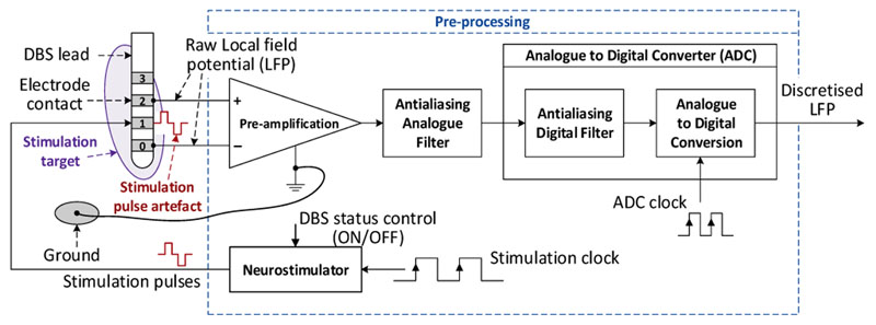
When LFPs are used as the feedback signal for clDBS, they are often recorded from the same electrode used for stimulation after pre-amplification, anti-aliasing filtering and analogue to digital conversion (ADC) (Fig. 1). Postprocessing by filtering and time-frequency decomposition are then employed to extract features for different applications.
Figure 1.
Classical approach of LFP recording for closed-loop DBS
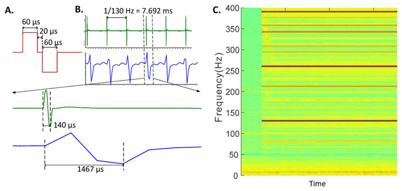
The nature of the stimulation artefacts in LFP recordings depends on the waveform and the pattern of stimulation, as well as on the properties and settings of the anti-aliasing filter, sampling frequency and the type of ADC. When narrow biphasic pulses of 60 - 200 μs duration are delivered to the target brain area at 100 - 200 Hz, as used in standard high frequency stimulation for the treatment of most movement disorders, the stimulation signal is composed of an infinite number of harmonics in the frequency domain. The antialiasing filter implemented before the ADCs is not sufficient to filter out the stimulation artefacts in the signal to be recorded. The simulation-induced artefacts in LFP recordings typically consist of a short, high-amplitude peak, which can be 106 times the amplitude of the neural activities, and coincide with the stimulation pulses. This is followed by an exponential decay superimposed on the local neural activity in the temporal domain, as shown by in vivo recordings both in animals [4, 5] and humans measured with successive approximation ADCs with sample-and-hold at high sampling rate (green lines in Fig. 2B). The total duration of the stimulation artefact is the sum of the duration of the stimulation pulse plus the duration for the exponential decay, which was between 20 ps and 100 ps in our measurements from different patients. However, with ADCs that are limited in acquisition frequency and amplitude range, the sharp stimulation pulses will be irregularly sampled leading to misrepresented and prolonged artefact waveforms in the temporal domain (blue lines in Fig. 2B). We observed prolonged artefacts lasting up to 1.5 ms in the temporal domain in measurements using amplifiers with sigma-delta ADC (TMSi Porti). These prolonged artefacts in LFP recordings are most probably the impulse response of the anti-aliasing and the digital decimation filter to the high amplitude pulses in the temporal domain (Fig. 2B). In the frequency domain, sampling at low frequency can lead to artefacts affecting the entire frequency spectrum (Fig. 2C), including many physiologically relevant frequency bands due to aliasing [6].
Figure 2.
Stimulation artefact in LFPs measured from the subthalamic nucleus in one human patient while biphasic stimulation pulses (A) were delivered at 130 Hz. B) LFP recordings in the temporal domain with either a SAR ADC at 83 kHz (Amplifier1902 +CED1401, green lines) or a Sigma-Delta ADC at 2048 Hz (TMSi Porti, blue lines). (C) Artefacts sampled at 2048 Hz using a Sigma-Delta ADC in frequency domain.
Three types of solutions have been proposed to mitigate stimulation-artefacts in LFP recordings: filtering, template removal and ‘blanking’. 1.) Filtering. Examples: Rossi et al. proposed a system based on a 10th order low-pass filter for reducing artefacts in LFP recordings in the frequency range of 2-40 Hz during DBS [7], and a high order analogue front-end Notch filter has been designed to suppress stimulation artefacts [8]. Stanslaski et al. adopted a system-level approach to mitigate the saturation and aliasing occurring in concurrent stimulation and recording using a first-order band-pass filter before amplification and analogue spectral analysis, followed by a third-order low-pass anti-aliasing filter before performing digital conversion [9]. Different filters have also been used after the ADC to extract useful features [1, 6]. However, most of these studies are only interested in LFP features within a limited frequency band. The artefacts in other frequency bands and in the time domain are not completely removed. 2.) Template removal. This is an extension of filtering in the time domain. It is based on the assumption that since the shape of the stimulation is known, one can “subtract” it from the recording in the temporal domain in order to recover the useful signal [10, 11]. However, this technique requires an estimation of the template of the artefact in real-time, which is challenging since the artefact signal is complex and potentially variable over time [12]. 3.) Blanking. In this method, the ADC holds the recording to its previous voltage before each stimulation pulse. Depending on the design of the circuit, the recovery time to recording mode ranges from 0.5 to 3 ms [12, 13]. Blanking is achievable with simple electronics. The main drawbacks are the long recovery time limiting the maximum recording frequency, and the discontinuity in the recorded data. In conclusion, real artefact-free continuous recording of LFPs during simultaneous stimulation still remains a challenge.
III. Proposed Methods
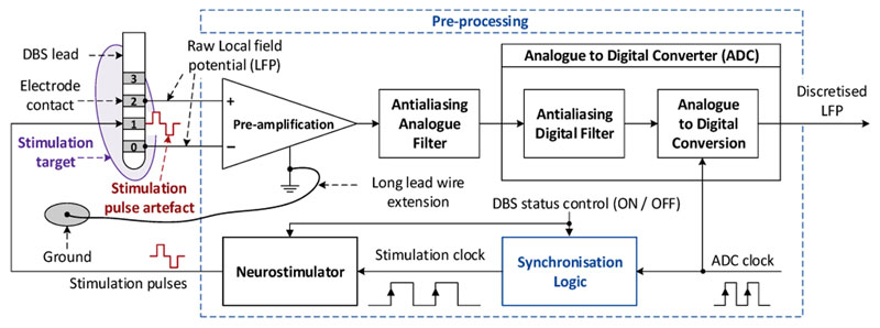
We propose the use of Successive approximation register ADCs (SARs) with sample-and-hold circuits to acquire the LFPs, and synchronise the clocks of the ADC and the stimulation to deliver the stimulation pulses between two successive ADC samples. This approach guarantees the regularity of both the ADC clock and the stimulator clock. Therefore, our approach complies with the Nyquist-Shannon condition, and maintains the integrity of the requirements of the digital Laplace transform necessary for closed-loop DBS to work as defined by digital control theory.
A. Design
The overall structure of the proposed method is presented in Fig. 3. The key component is the synchronization logic function, which generates synchronized clocks that drive the digital conversion and the generation of the stimulation pulses. We assume that the ADC circuit is able to adequately digitize LFPs with the resolution of 1 μV or less after preamplification and anti-aliasing filtering, despite potential DC biases and different sources of noises (thermal noise from the different electronic circuits, power supply and switching component noises, and noise from the room environment).
Figure 3.
Proposed approach for LFP recording for closed-loop DBS
In the synchronisation logic function (Fig. 4), we set a constant integer ratio (n) between the ADC sampling rate and the simulation pulse frequency. The sub-function “Divider” is a modulo-n frequency divider that divides the input ADC clock fs by n. The reduced clock signal fr is delayed by a constant time (Δt) depending on the duration the ADC requires to fully complete one conversion. Δt is 1 to 10 ps for standard ADCs, and it can be less than 1 ps for high performance ADCs. The resultant delayed clock signal fd is then enabled or disabled by the function “Selection” controlled by the DBS status control input: if the DBS status is ON, the clock signal is transferred to the output to become the stimulation clock fstim; otherwise, it is blocked, and the stimulation pulse remains at 0 (thus inactive).
Figure 4.
Synchronisation logic function of the proposed method
B. Illustrative example
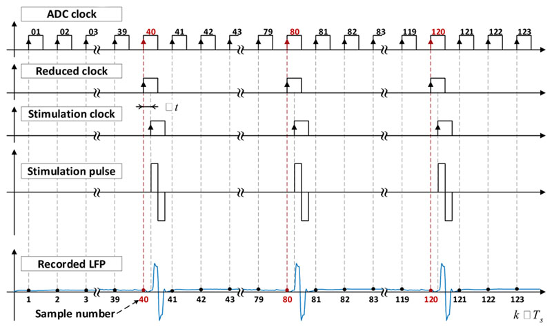
As an example, we consider a stimulation pulse that lasts for 140 μs (biphasic pulse with an interphase gap of 20 μs) and is delivered at 130 Hz, exponential decay duration of 50 μs and an ADC with a conversion time (Δt) of 1 μs. In this case, the total duration of the artefacts plus the conversion time is 191 μs. Thus, the maximum ADC sampling frequency possible is derived by: fs_max = 1/191 μs ≈ 5.24 kHz. The maximal integer ratio between the neurostimulation and the ADC is 40. Therefore, the ADC clock frequency can be set to any integer number times the stimulation frequency with the integer number smaller or equal to 40. Fig. 5 shows a typical chronogram of the method proposed at the maximum sampling frequenting for the pulse parameters above. The ADC Clock Generator produces a square wave clock of 5.2 kHz. At each rising edge, the ADC realizes one conversion of the LFP signal; and at each modulo-n sample (40, 80, 120, etc.), a rising edge is generated at the reduced clock signal fr, which is then delayed by the specified Δt to generate the delayed clock fd. When the Neuromodulation status control is set to ON, a stimulation pulse of 140 ps is delivered at each rising edge of the stimulation clock fstim, which induces the typical artefacts in the original LFPs. With the method proposed here, the stimulation pulses necessarily happen between two ADC samplings, so they are guaranteed to be never sampled. Therefore, this method achieves a true “artefact-free” recording by adequately synchronising the ADC and pulse generation.
Figure 5.
Illustrative chronogram of the different clocks
C. Implementation and test
We tested the efficacy of the proposed method using a custom-built stimulator which can generate a stimulation pulse with controllable shape at each rising edge of an input clock (the stimulation clock). For the test, we set the stimulation pulses to be biphasic with total length of 140 ps (shown in Fig. 2A). An Arduino Due board with successive approximation ADCs was configured to perform one A/D conversion at each rising edge of another clock (the ADC clock). The time required for one A/D conversion for the Arduino Due was 1 μs. A function generator (AFG-2105 by GW Instek) was used to generate an analogue sinewave representing the actual LFP signal and square wave pulse trains at 19.5 kHz representing the master clock for the test. The master clock from the function generator was fed into the Arduino Due and divided by an integer number 10 internally via the Arduino timer to provide the ADC clock at 1.95 kHz.
When clock synchronization was activated, the master clock is first divided by the integer number 150 using a programmable divider to produce the reduced clock fr, which is then delayed by 10 μs with a first-order low-pass (RC) circuit followed by two Schmitt trigger inverting gates to produce the delayed clock fd. An ‘And’ function between this clock and the DBS status control implements the selection function generating the stimulation clock fstim, which drives the custom-built stimulator to generate the stimulation pulse at 130 Hz. This way the ADC clock and the stimulation clock are synchronised with an integer ratio of 15 (< max ratio of 40) between the ADC sampling rate and stimulation frequency. When the clock synchronization is de-activated, another independent clock at 130 Hz is generated to drive the custom-build stimulator to generate stimulation pulses independent from the ADC clock.
The stimulation pulses pass through an RC circuit modelling the Electrode-to-tissue-interface (ETI) ([4, 5, 12]) to generate artefacts as the response of the brain tissue to the stimulation pulses. Due to the resolution limit of the ADC used for this test, the ratio of the simulated LFP signal and stimulation artefacts was set to 1:10. The analogue sum of the simulated LFP signal and rescaled artefacts produces the analogue signal (LFP) with artefacts, which is sampled by the Arduino ADC. The sampled data are converted back to analogue outputs by the DAC of the Arduino Due and filtered by a second-order low-pass Butterworth filter (based on a Sallen-Key circuit) with a cut-off frequency of around 300 Hz to simulate the post-ADC filtering used in many commercial amplifiers. The signals after ADC and filtering were recorded with a PicoScope 5442B from PicoTech, which has a resolution of 14 bits hardware plus 2 bits software and a bandwidth of 60 MHz with its original tuned probe MI007, using the PicoScope software v6.13.17.4271 (2019).
IV. Results
A. LFP recording without clock synchronization
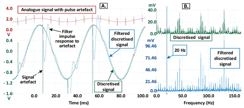
We first simulated the case of a 20 Hz LFP signal with 130 Hz biphasic stimulation, and an ADC frequency of 1.95 kHz. When the ADC clock and the neurostimulation clock are not synchronized, in the time domain (Fig. 6A), there are large artefacts in the discretized signal (green trace) consisting of short, high-amplitude peaks (impulses).
Figure 6.
Recording without clock synchronization in the temporal-domain (A) and frequency-domain (B).
The high-amplitude peaks in the discretized signal illicit prolonged oscillations in the filtered discretized signal (blue trace in Fig. 6A), which are the impulse response of the second order low-pass filter. This also illustrates how the digital decimation filter in Sigma-Delta ADCs might lead to prolonged stimulation related artefacts in the recorded signal. In the frequency domain (Fig. 6B), the artefact harmonics alias in a complex pattern (green trace) that extends from the low frequency band (below 10 Hz) to beyond 100 kHz. Even with the second-order filter after the ADC, there are still harmonics below 100 Hz (blue traces in Fig. 6B). The discretization by the ADC causes the expected stair-like effect in the recorded signal, leading to high frequency harmonics even with no stimulation. But, these high frequency harmonics due to the discretization can be removed by a low-pass filter.
B. LFP recording with clock synchronization
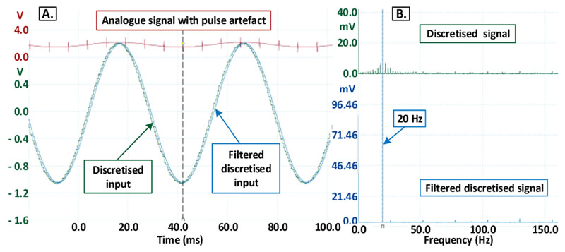
The results of the recording with clock synchronisation are shown in Fig. 7A. The striking difference is the total absence of any pulse artefacts or filter impulse responses (green trace) in the temporal doamin. In the frequency domain, there are no aliased harmonics in the lower frequency band of interest (between 1 to 500 Hz), as seen in Fig. 7B (blue trace).
Figure 7.
Recording with clock synchronization in the temporal domain (A) and the frequency domain (B).
V. Discussion
Here we show that true continuous artefact-free recording with stimulation can be achieved by synchronizing the clocks of the ADC sampling and neurostimulator by maintaining an integer ratio between sampling and stimulation frequencies. This approach can be easily scaled to multi-channel recordings, and can be combined with different types of ADCs with resolutions suitable for different applications. This method is not limited to LFP recording, but to any application where simultaneous stimulation and recording is required and the stimulation leads to disturbance of the recorded signal.
It should be recognized that our method imposes a fixed relationship between the ADC sampling frequency and the stimulation frequency. If it is a priority to be able to set any arbitrary (real) value to the stimulation frequency, we can set the stimulation frequency to be a flexible input for the user and change the sampling frequency accordingly. Meanwhile, our method also imposes a maximal ADC sampling rate (fs max) depending on the total pulse width (Td) of the stimulation plus, the duration of the exponential decay (Te) and the time required for one A/D conversion (Tc): Fs_max = 1/(Td + Te +Tc). With an ADC conversion time of 1 μs, a standard total pulse width of 140 μs and a slow exponential decay lasting 100μs, the maximal sampling frequency is 4.15 kHz. With a wide total pulse width of 400 μs, the maximal sampling frequency is 2 kHz, which is still sufficient for LFP recordings since the useful information in LFPs is normally below 500 Hz [3].
There are a few assumptions and requirements in order to guarantee optimal performance of the proposed method in practical situations which need to be considered. 1.) Successive approximation register (SAR) ADCs with sample-and-hold amplifiers are required to implement the method proposed here; or at least, it should be possible to control the start of the conversion on demand. Compared with delta-sigma (Δ∑) ADCs, SAR ADCs realise one conversion at each rising/falling edge of their sampling clock; thus, allowing the exact control of the time points to initiate the analogue to digital conversion. 2.) Stimulation-induced polarisation of the sensing electrode, which is caused by accumulated charge in the electrodes, tends to lead to a slow exponential decay superimposed on neural activities. The polarisation can be greatly reduced when active discharge techniques, such as charge-balanced biphasic stimulation pulses, are used [14]. 3.) A further practical consideration concerns the potential saturation of the pre-amplifier due to large stimulation artefacts. Several techniques have been already developed to deal with this problem, but are beyond the scope of this report.
Clinical Relevance.
The method proposed here provides continuous and artefact-free recording of LFPs close to the stimulation target, and thereby facilitates the implementation of more advanced closed-loop DBS using LFPs as feedback.
References
- [1].Little S, et al. Adaptive deep brain stimulation in advanced Parkinson disease: Adaptive DBS in PD. Ann Neurol. 2013 Sep;74(3) doi: 10.1002/ana.23951. 449457. [DOI] [PMC free article] [PubMed] [Google Scholar]
- [2].Tan H, et al. Decoding voluntary movements and postural tremor based on thalamic LFPs as a basis for closed-loop stimulation for essential tremor. Brain Stimulation. 2019 Jul;12(4):858–867. doi: 10.1016/j.brs.2019.02.011. [DOI] [PMC free article] [PubMed] [Google Scholar]
- [3].Zhou A, Johnson BC, Muller R. Toward true closed-loop neuromodulation: artifact-free recording during stimulation. Curr Opin Neurobiol. 2018 Jun;50:119–127. doi: 10.1016/j.conb.2018.01.012. [DOI] [PubMed] [Google Scholar]
- [4].Miocinovic S, et al. Experimental and theoretical characterization of the voltage distribution generated by deep brain stimulation. Exp Neurol. 2009 Mar;216(1):166–176. doi: 10.1016/j.expneurol.2008.11.024. [DOI] [PMC free article] [PubMed] [Google Scholar]
- [5].Wei XF, Grill WM. Impedance characteristics of deep brain stimulation electrodes in vitro and in vivo. J Neural Eng. 2009 Aug;6(4) doi: 10.1088/1741-2560/6/4/046008. 046008. [DOI] [PMC free article] [PubMed] [Google Scholar]
- [6].Lio G, Thobois S, Ballanger B, Lau B, Boulinguez P. Removing deep brain stimulation artifacts from the electroencephalogram: Issues, recommendations and an open-source toolbox. Clin Neurophysiol. 2018 Oct;129(10):2170–2185. doi: 10.1016/j.clinph.2018.07.023. [DOI] [PubMed] [Google Scholar]
- [7].Rossi L, Foffani G, Marceglia S, Bracchi F, Barbieri S, Priori A. An electronic device for artefact suppression in human local field potential recordings during deep brain stimulation. J Neural Eng. 2007;4(2):96. doi: 10.1088/1741-2560/4/2/010. [DOI] [PubMed] [Google Scholar]
- [8].Petkos K, et al. A high-performance 4 nV/√ analog front-end architecture for artefact suppression in local field potential recordings during deep brain stimulation. J Neural Eng. 2019 Oct;16(6) doi: 10.1088/1741-2552/ab2610. [DOI] [PMC free article] [PubMed] [Google Scholar]
- [9].Stanslaski S, et al. Design and Validation of a Fully Implantable, Chronic, Closed-Loop Neuromodulation Device With Concurrent Sensing and Stimulation. IEEE Trans NeuralSyst Rehabil Eng. 2012 Jul;20(4):410–421. doi: 10.1109/TNSRE.2012.2183617. [DOI] [PubMed] [Google Scholar]
- [10].Al-ani T, Cazettes F, Palfi S, Lefaucheur J-P. Automatic removal of high-amplitude stimulus artefact from neuronal signal recorded in the subthalamic nucleus. J Neurosci Methods. 2011 May;198(1):135–146. doi: 10.1016/j.jneumeth.2011.03.022. [DOI] [PubMed] [Google Scholar]
- [11].Qian X, Chen Y, Feng Y, Ma B, Hao H, Li L. A Method for Removal of Deep Brain Stimulation Artifact From Local Field Potentials. IEEE Trans Neural Syst Rehabil Eng. 2017 Dec;25(12):2217–2226. doi: 10.1109/TNSRE.2016.2613412. [DOI] [PubMed] [Google Scholar]
- [12].Lempka SF, Howell B, Gunalan K, Machado AG, McIntyre CC. Characterization of the stimulus waveforms generated by implantable pulse generators for deep brain stimulation. Clin Neurophysiol. 2018 Apr;129(4):731–742. doi: 10.1016/j.clinph.2018.01.015. [DOI] [PMC free article] [PubMed] [Google Scholar]
- [13].Blum RA, Ross JD, Brown EA, DeWeerth SP. An integrated system for simultaneous, multichannel neuronal stimulation and recording. IEEE Transactions on Circuits and System. 2007;54(12):2608–2618. [Google Scholar]
- [14].Sooksood K, Stieglitz T, Ortmanns M. An Active Approach for Charge Balancing in Functional Electrical Stimulation. IEEE Trans Biomed Circuits Syst. 2010 Jun;4(3):162–170. doi: 10.1109/TBCAS.2010.2040277. [DOI] [PubMed] [Google Scholar]


