Summary
Balanced fusion and fission are key for proper function and physiology of mitochondria1,2. Remodelling of the mitochondrial inner membrane (IM) is mediated by dynamin-like Mitochondrial genome maintenance 1 protein (Mgm1) in fungi or the related Optic atrophy protein 1 (OPA1) in animals3–5. Mgm1 is required for the preservation of mitochondrial DNA in yeast6, whereas mutations in the OPA1 gene in humans are a common cause for autosomal dominant optic atrophy, a genetic disorder affecting the optical nerve7,8. Mgm1 and OPA1 are present in mitochondria as a membrane-integral long (l) form and a short (s) form that is soluble in the intermembrane space. Yeast strains expressing temperature-sensitive mutants of Mgm19,10 or mammalian cells devoid of OPA1 display fragmented mitochondria11,12, suggesting an important role of Mgm1/OPA1 in IM fusion. Consistently, only the mitochondrial outer membrane (OM), but not the IM, fuses in the absence of functional Mgm113,14. Mgm1 and OPA1 have also been shown to maintain proper cristae architecture10,14. For example, OPA1 prevents the release of pro-apoptotic factors by tightening cristae junctions15. Finally, s-OPA1 localises to mitochondrial constriction sites, where it presumably promotes mitochondrial fission16. How Mgm1/OPA1 perform their diverse functions in membrane fusion, scission, and cristae organisation is at present unknown. Here, we present crystal and electron cryo-tomography (cryo-ET) structures of Chaetomium thermophilum Mgm1. Mgm1 consists of a GTPase domain, a bundle signalling element (BSE) domain, a stalk, and a paddle domain containing a membrane binding site. Biochemical and cell-based experiments demonstrate that the Mgm1 stalk mediates assembly of bent tetramers into helical filaments. Cryo-ET of Mgm1-decorated lipid tubes and fluorescence microscopy experiments on reconstituted membrane tubes indicate how the tetramers assemble on positively or negatively curved membranes. Our findings convey how Mgm1/OPA1 filaments dynamically remodel the mitochondrial IM.
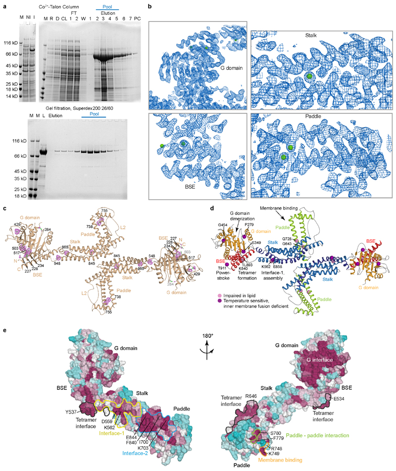
We purified and crystallised a truncated s-Mgm1 isoform from the thermophilic fungus Chaetomium thermophilum (from here on Mgm1) (Fig. 1a, Extended Data Fig. 1a, Supplementary Data Fig. 1). Crystals of this construct grown in the absence of nucleotides diffracted to 3.6 Å resolution. The structure was solved by single anomalous dispersion (Extended Data Fig. 1b, c, Extended Data Table 1).
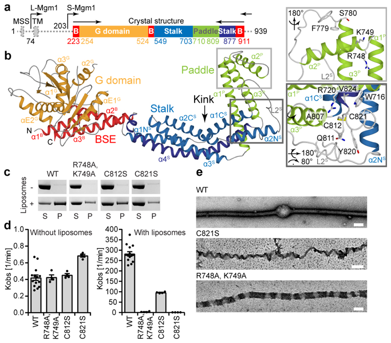
Figure 1. Structure of Mgm1 reveals a paddle domain required for membrane binding.
a, Domain and isoform architecture of Mgm1. MSS – mitochondrial signal sequence, TM - transmembrane domain. L – long, S – short isoform of Mgm1. B – BSE. b, Ribbon type presentation of Mgm1. Domains are coloured individually as in a. The inset shows the disulphide bond between the conserved cysteine residues C812 and C821 and the conserved positively charged residues R748, K749 in the paddle domain. Note that C821 is in the center of the paddle while C812 is closer to its periphery. Apart from the loss of the disulfide bridge, the C821S mutation may therefore disturb the paddle conformation more strongly than C812S. c, Representative liposome binding experiment. S – Supernatant; P – Pellet (n = 4 independent experiments). d, GTPase activity (n = 4 independent experiments) and e, negative-stain EM of liposome tubulation of WT and indicated mutants (n = 2 independent experiments). Quantification of all experiments is available in Extended Data Fig. 3a and raw data in Supplementary Fig. 2. Data in d represent mean values and error bars indicate SEM. Scale bars in e are 50 nm.
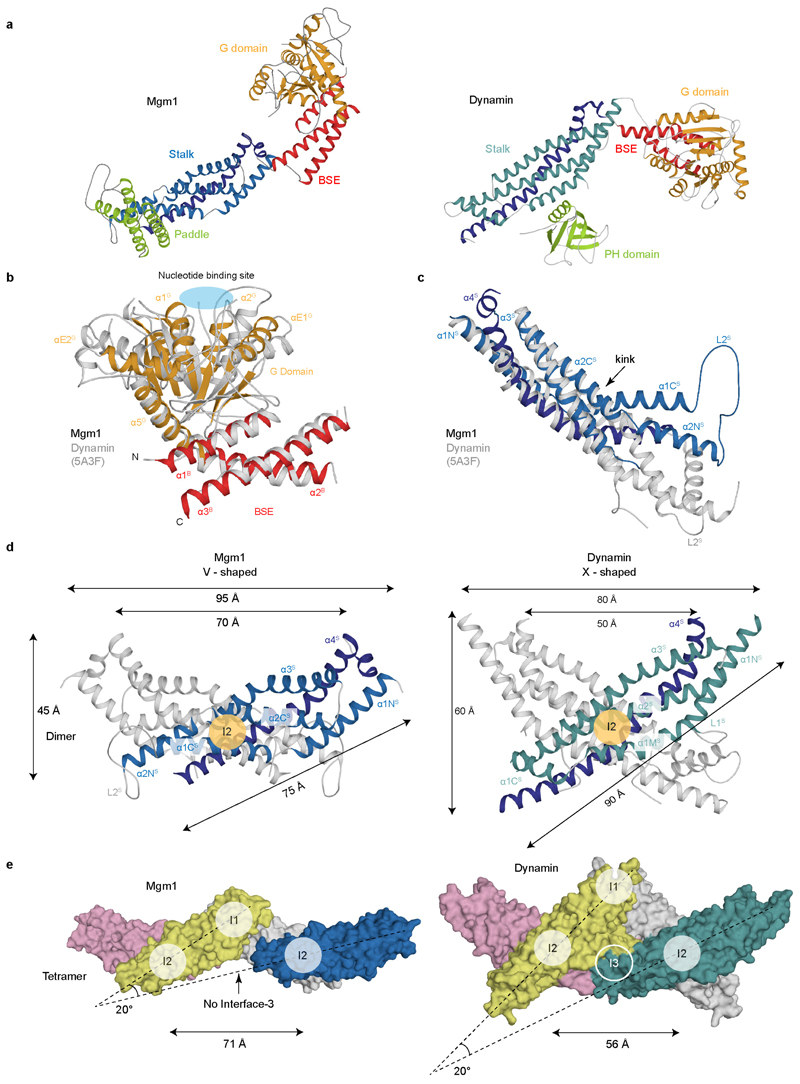
The structure of Mgm1 contains four domains: A G domain, a bundle signalling element (BSE) domain, a stalk, and a paddle (Fig. 1a, b). The G domain closely resembles that of human dynamin (Extended Data Fig. 2). An interface across the nucleotide-binding site responsible for G domain dimerisation in the dynamin superfamily (the ‘G interface’) is highly conserved in Mgm1 (Extended Data Fig. 1e). The adjacent BSE domain consists of three helices derived from different regions of Mgm1 (Fig. 1a, b). The BSE domain contacts the G domain, as in the closed conformation of dynamin17-19. The Mgm1 stalk domain is shorter than the dynamin stalk, comprising an antiparallel kinked four-helix bundle (Fig. 1b, Extended Data Fig. 2c, d). Unique to Mgm1 is the paddle, an elongated three-helix domain at the tip of the stalk, which is inserted between stalk helices α3 S and α4 S and contains a disulphide bridge linking Cys812 to Cys821 (Fig. 1b). Dynamin has a membrane-binding pleckstrin homology domain in the corresponding position.
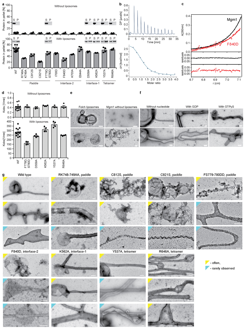
We mutated two positively charged, surface-exposed residues as well as the two cysteines of the disulphide bridge in the paddle. In co-sedimentation experiments, the Mgm1 construct efficiently bound to Folch liposomes (lipids from bovine brain), whereas the mutants bound less strongly (Fig. 1c, Extended Data Fig. 3a). Mgm1 bound to the non-hydrolysable GTP analogue GTPγS with a Kd of 9 μM (Extended Data Fig. 3b). The intrinsic GTPase activity of Mgm1 (about 0.5 min-1 at 37 °C) was stimulated about 500-fold in the presence of Folch liposomes, reaching rates of 270 min-1. Liposomes also accelerate the GTPase activity of yeast Mgm1 and human OPA120, 21. Stimulation of GTPase activity was significantly reduced for all paddle mutants (Fig. 1d).
When incubated with liposomes, Mgm1 induced tubulation and coated the membrane surface in a regular pattern (Fig. 1e), with or without added nucleotide (Extended Data Fig. 3e, f). The membrane remodelling activity of the paddle mutants was reduced, indicating that the paddle constitutes a membrane-binding site (Fig. 1e, Extended Data Fig. 3g).
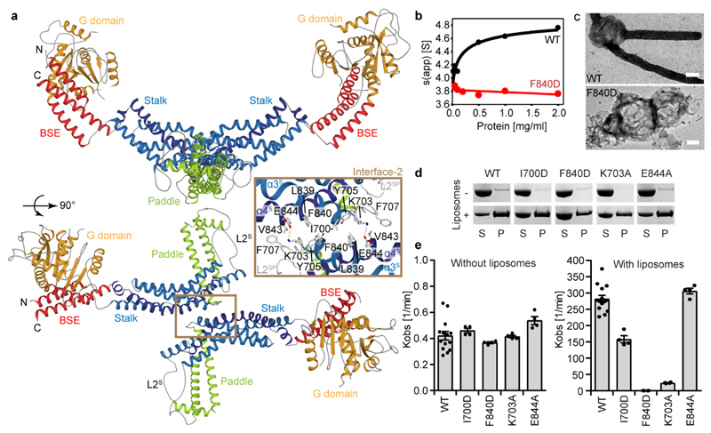
The asymmetric unit of the crystals contained an Mgm1 dimer. The dimer interface (termed interface-2, in analogy to dynamin17, 18) includes a hydrophobic core which is flanked by polar residues (Fig. 2a). By analytical ultracentrifugation (AUC), we detected a concentration-dependent monomer-dimer equilibrium for Mgm1 (Fig. 2b, Extended Data Fig. 3c). The F840D mutation in the centre of the hydrophobic dimer interface rendered the protein monomeric. Assembly via the Mgm1 stalk interface-2 results in a V-shaped dimer, whereas dynamin stalks form an X-shaped dimer (Extended Data Fig. 2d, e).
Figure 2. The Mgm1 dimer.
a, The dimer is formed via interface-2 between opposing stalks. b, Sedimentation velocity analysis of Mgm1 and the F840D mutant at different protein concentrations. The unusually small sedimentation coefficients for both the monomeric and dimeric species fit well with their non-globular structures. The Mgm1 data can be fitted to a KD of 1 μM. n = 1. c, Negative-stain EM of tubulated liposomes for wild-type (WT) and interface-2 F840D mutant. Scale bars are 50 nm, n = 2 independent experiments. d, Liposome binding and e, GTPase activity for selected mutants in interface-2 (n = 4 independent experiments). Data in e represent mean values; error bars indicate SEM.
Mutations of several interface-2 residues reduced liposome binding and liposome-stimulated GTPase activity (Fig. 2d, e, Extended Data Fig. 3a). The most severe mutant, F840D, failed to tubulate liposomes and did not form a regular protein pattern (Fig. 2c-e, Extended Data Fig. 3g), confirming the importance of interface-2 for Mgm1 assembly on the membrane surface.
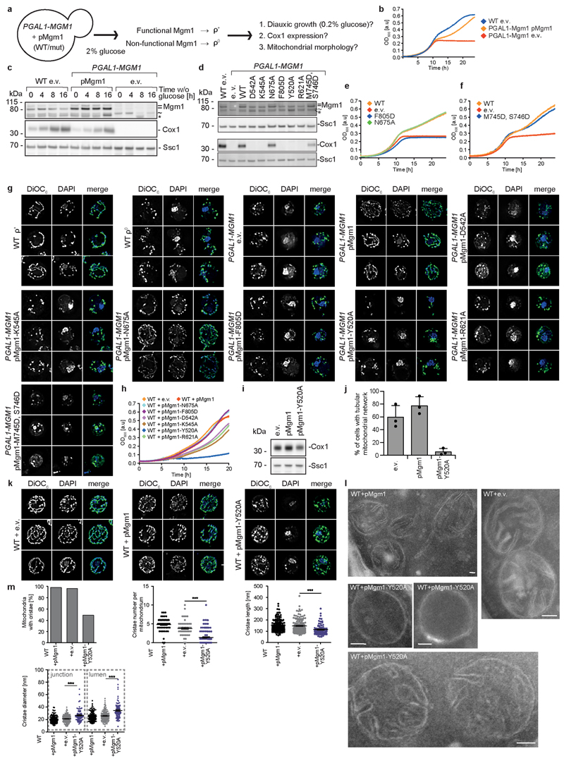
We used a yeast model system to express Mgm1 mutants in a strain in which the expression of endogenous Mgm1 was under control of the galactose-inducible and glucose-repressed GAL1 promoter (Extended Data Fig. 4a). Loss of Mgm1 expression was associated with a rapid and irreversible loss of the mitochondrial genome, fragmentation of the mitochondrial network and the subsequent inability to switch to respiratory metabolism upon glucose depletion (Extended Data Fig. 4b, c)6, 10. Re-expression of yeast Mgm1 rescued the loss of mitochondrial respiratory function, as assessed by yeast growth, the presence of mitochondrially-encoded cytochrome c oxidase 1 protein (Cox1) and restoration of the mitochondrial network (Extended Data Fig. 4b-g). In line with the liposome-binding assays, the yeast F805D mutant (corresponding to F840D in Mgm1), but not the N675A mutant (corresponding to I700D in Mgm1, Supplementary Fig. 1), failed to complement the loss of endogenous Mgm1 (Extended Data Fig. 4d, e, g). These results highlight the importance of interface-2 for Mgm1-dependent maintenance of mitochondrial DNA and respiration-competent mitochondria.
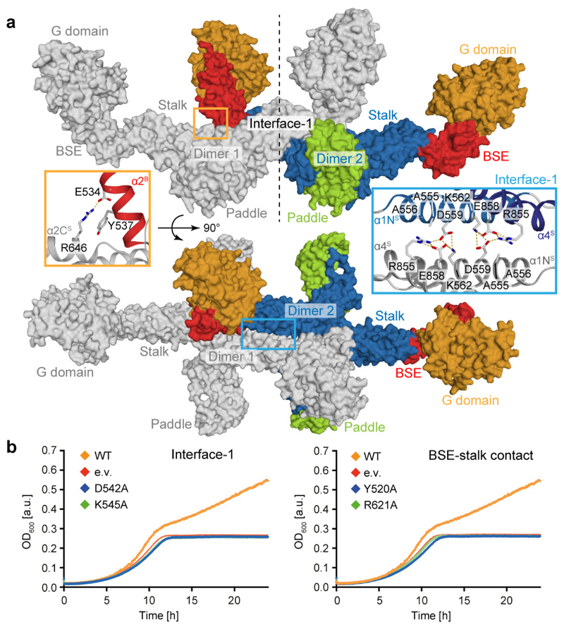
In the crystals, two Mgm1 dimers assembled into a tetramer via another ~1000 Å2 stalk interface which, again in analogy to dynamin, we refer to as stalk interface-1 (Fig. 3a). The tetramer is further stabilised by a ~1100 Å2 contact between the BSE domain of one dimer and the stalk of the adjacent dimer. Interface-1 and the BSE/stalk contact site are highly conserved in the Mgm1 family (Extended Data Fig. 1e). Notably, the interface-1 interaction induces a 20° bend between two stalk dimers (Extended Data Fig. 2e).
Figure 3. Assembly mechanism of Mgm1.
a, Tetramer as seen in the crystal. Two dimers (grey or color-coded by domain) interact via stalk interface-1 and a small BSE – stalk contact. See insets for details. b, Yeast respiratory growth complementation assays with Mgm1 mutants in interface-1 (left, D542, K545 in yeast corresponds to D559, K562 in Chaetomium thermophilum Mgm1) and the BSE – stalk contact (right, Y520, R621 in yeast corresponds to Y537, R646 in Chaetomium thermophilum Mgm1). Representative growth curve (n = 3 independent experiments). e.v. – empty vector control, OD – optical density, see also Extended Data Fig. 4.
Mgm1 mutants D559A or K562A in interface-1 and Y537A or R646A in the BSE/stalk contact did not show major differences in liposome binding or GTPase activity compared to Mgm1 (Extended Data Fig. 3a, d). The mutants also tubulated liposomes and formed a regular pattern on the membrane (Extended Data Fig. 3g). However, when introduced into the corresponding positions of yeast Mgm1, all mutants failed to complement the loss of wild-type Mgm1 in respiratory growth (Fig. 3b), mitochondrial genome maintenance and mitochondrial morphology (Extended Data Fig. 4d, g). Interestingly, the Y520A BSE/stalk contact mutant in the tetramer interface exerted a strong dominant negative effect on respiratory yeast growth when co-expressed with endogenous Mgm1 (Extended Data Fig. 4h). The corresponding yeast strain retained mitochondrial DNA (Extended Data Fig. 4i), allowing us to examine Mgm1-specific deficits on mitochondrial morphology and ultrastructure. Expression of Y520A induced fragmentation of the mitochondrial network (Extended Data Fig. 4j, k), reduced cristae number and length and an increased cristae diameter (Extended Data Fig. 4l, m).
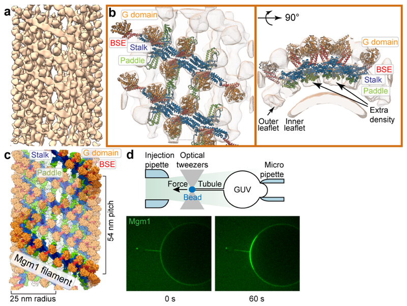
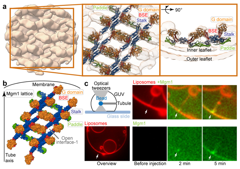
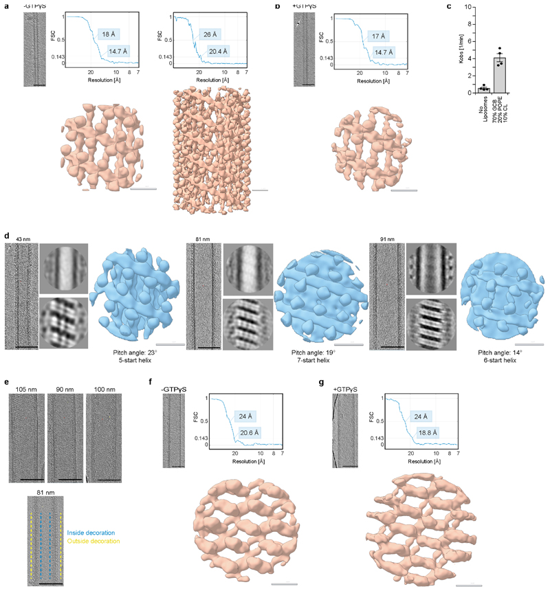
We used electron cryo-tomography (cryo-ET) and subtomogram averaging to determine the structure of membrane-bound Mgm1 (Fig. 4a, b, Extended Data Fig. 5a, b). In the absence of nucleotide, or upon addition of GTPγS, Mgm1 remodelled Folch liposomes into membrane tubes of varying diameters, ranging from ~18 - 140 nm. The Mgm1 coat decorated membrane tubes in a regular lattice. For subtomogram averaging, preformed tubes of ~20 nm diameter were used in order to increase the number of particles for averaging. These tubes also stimulated the GTPase activity of Mgm1, although less strongly than Folch liposomes (Extended Data Fig. 5c). The final resolution of the subtomogram average (STA) volume was 14.7 Å for the nucleotide-free and nucleotide-bound forms (Extended Data Table 1). No significant differences were apparent between the two STA volumes. Strikingly, the Mgm1 tetramer fits the STA volume with only minor positional domain rearrangements (Fig. 4b, Extended Data Fig. 6a, c, e). The G domain was in a closed conformation relative to the BSE domain and located furthest from the membrane, the stalk was in the middle, and the paddle was next to the membrane. The Mgm1 coat in Fig. 4b-c can be viewed as a left-handed four-start helix, consisting of four parallel helical filaments (Extended Data Fig. 7a, b). Similar filaments were observed on Folch lipid tubes of different diameter, although their helical parameters varied (Extended Data Fig. 5d). The filament backbone was formed by stalks oligomerising in an alternating fashion via interfaces-1 and 2. This contrasts with dynamin filaments, where the stalks oligomerise via three interfaces (Extended Data Fig. 2e)22, 23. As another difference to dynamin22, we did not observe G domain interactions between adjacent helix turns. Instead, contact was established through the paddle domains (Fig. 4b, c, Extended Data Fig. 6a). Mutations of the conserved residues F779 and S780 in the paddle contact site affected membrane binding and stimulated GTPase activity only mildly (Extended Data Fig. 3a, d). Expression of the corresponding Mgm1 mutant in yeast complemented the loss of endogenous Mgm1 with respect to respiratory growth, but the cells exhibited moderate alterations of mitochondrial morphology and mitochondrial genome maintenance (Extended Data Fig. 4d, f, g).
Figure 4. Mgm1 forms a helical lattice on the outside of lipid tubes.
a, Mgm1 forms a regular protein coat on the outer surface of a galactocerebroside-containing lipid tubes, allowing cryo-ET analysis. b, The sub-tomogram average shows the protein lattice with Mgm1 flexibly fitted into the cryo-ET volume of the apo form. The outer leaflet of the membrane is not well defined in this reconstruction. Arrows indicate density not attributable to the protein that was assigned to the outer membrane leaflet. c, Four filaments of Mgm1 dimers wrap around a membrane tube in a left-handed surface lattice. Stalks assemble via alternating interface-1 and 2 (Extended Data Fig. 7). d, Tube-pulling assay for generating a tube surface accessible from the outside. Mgm1 (green fluorescence) binds to the tube and the GUV surface (n = 8 independent experiments).
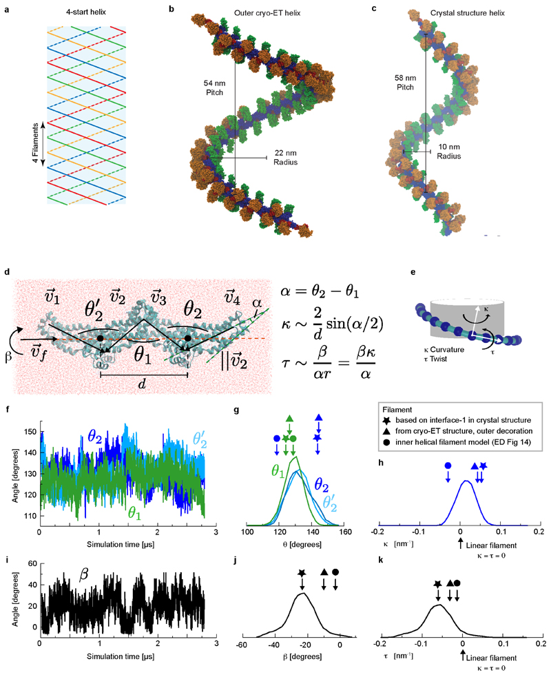
The tendency for Mgm1 to form a left-handed helix on the convex exterior of membrane tubes is consistent with the curvature of the crystallographic tetramer that arises from the interaction of interface-1. A model in which several dimers are connected via identical interfaces-1 results in a continuous filament with dimensions and helix parameters (radius, pitch) similar to those observed by cryo-ET (Extended Data Fig. 7b, c). Microsecond-scale molecular dynamics simulations (MD) starting from the crystallographic tetramer provide further evidence for the curvature preference of the Mgm1 interface-1 (Extended Data Fig. 7d-k). The most likely curvature and twist in the simulated interface-1 was the same as in the crystal lattice. The simulation results suggested sufficient flexibility to account for variability in the radii of tubes decorated on the outer membrane surface.
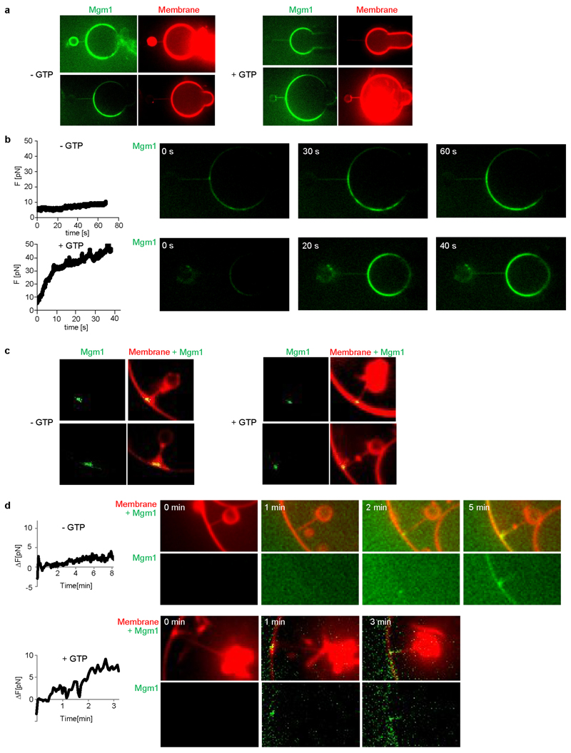
We followed the dynamics of Mgm1 assembly on the membrane by live fluorescence confocal imaging. By manipulating streptavidin beads adhering to giant unilamellar vesicles (GUVs) with optical tweezers24, membrane tubes can be pulled out of the GUV in a controlled manner. Mgm1 was then injected into the chamber with a second pipette (Fig. 4d).
Consistent with cryo-ET and negative-stain EM results, Mgm1 adapted to different degrees of membrane curvature by decorating the outer surface of the membrane tube and the GUV. GTP addition after assembly did not result in membrane scission under these conditions, but the force required to hold the tube in place (measured as a function of bead displacement) increased by a factor of 3 to 5. This is consistent with a GTP-dependent structural rearrangement of the Mgm1 coat and/or a GTP-dependent expansion of the membrane tube (Extended Data Fig. 8a, b).
Cryo-ET analysis revealed that Mgm1 occasionally decorated the inside surface of Folch membrane tubes in a regular pattern, suggesting that the liposomes were leaky (Fig. 5a, Extended Data Fig. 5e). In further experiments, liposomes were sonicated for a few seconds after adding Mgm1 to promote formation of the internal lattice. Tubes with an internal lattice were much wider and less variable in diameter (range 90-105 nm) (Extended Data Fig. 5e). The negative (concave) membrane curvature on the inner surface of a larger tube resembles the inside of mitochondrial cristae. Subtomogram averages of Mgm1 decorating the inner vesicle surface were obtained for the nucleotide-free and GTPγS-bound form (Fig. 5, Extended Data Fig. 5f, g, Extended Data Table 1). At an estimated resolution of 20.6 Å for the nucleotide-free and 18.8 Å for the nucleotide-bound form, the STA volumes appeared very similar.
Figure 5. Mgm1 forms a lattice on the inside of lipid tubes.
a, Mgm1 in the apo form decorates the inner surface of lipid tubes. The subtomogram average reveals regular protein arrays on the inner surface of membrane tubes; a close-up view shows Mgm1 flexibly fitted into the cryo-ET volume, with the G domains dimerised via the G interface. b, Mgm1 lattice on the inner membrane surface of a tube. Interface-1 between tetramers is open, while contacts of G domains and paddle domains stabilise the lattice, see also Extended Data Fig. 6. c, Tube-pulling assay for generating a membrane tube accessible from the inside. Lipid fluorescence is red. Mgm1 (green fluorescence) binds to the neck and the inner surface of the tube. The arrow points to the entry of the membrane tube (n = 7 independent experiments).
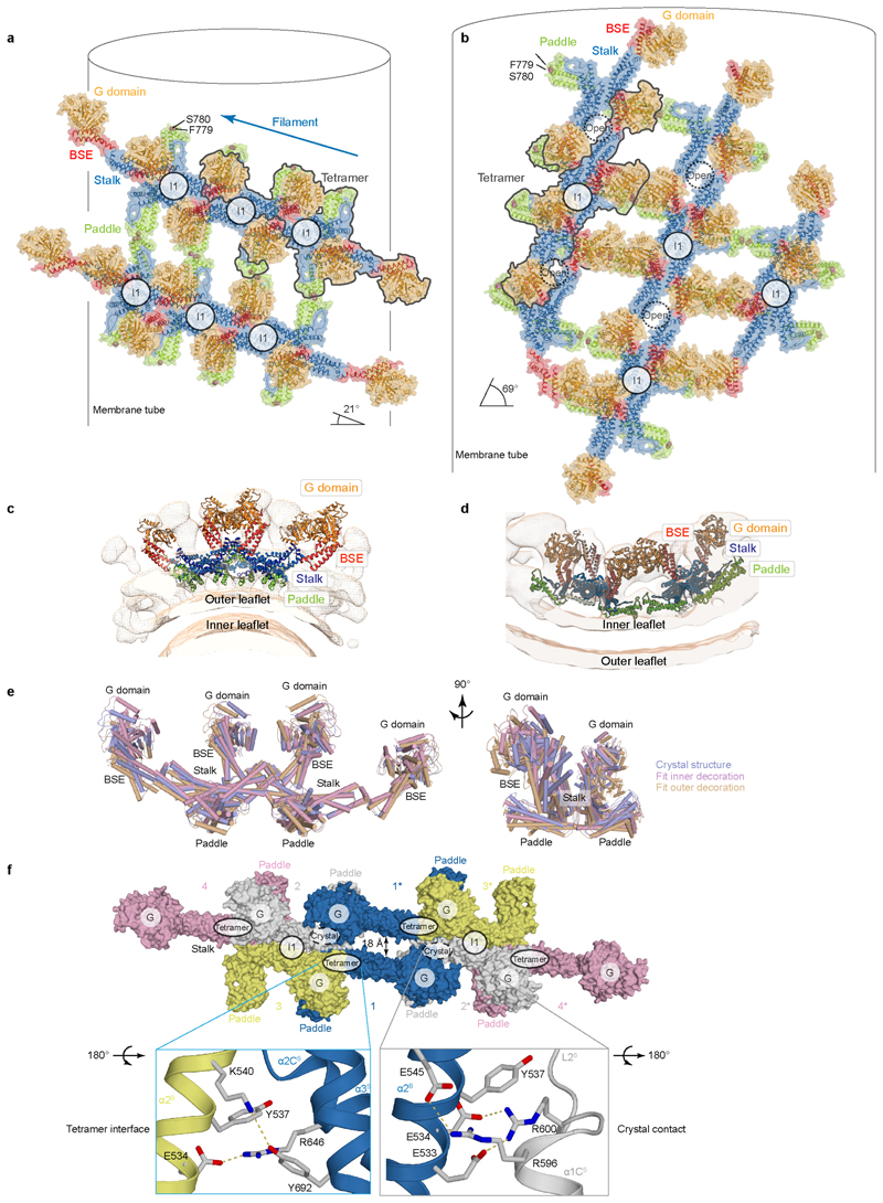
As in the external lattice, the crystallographic Mgm1 tetramer fitted the STA volume of the internal lattice with only minor rearrangements (Fig. 5a, b, Extended Data Fig. 6b, d, e). The G domains were furthest from the membrane facing into the tube, the stalk was in the middle and the paddle domain was next to the membrane. The arrangement of tetramers on the internal lattice differed markedly from that on the external membrane surface (Fig. 5a, b, Extended Data Fig. 6a-e). Rather than through interface-1, assembly involved a contact between neighbouring tetramers that included conserved patches in the BSE and stalk domains, closely resembling the linear arrangement of tetramers in the crystal lattice (Extended Data Fig. 6f). The angle between filaments of Mgm1 tetramers and the plane perpendicular to the tube axis was 69°, whereas it was 21° in the external lattice (Fig. 5b, Extended Data Fig. 6a, b). As another major difference to the external lattice, G domains were in close contact, and their orientation indicated that they interacted though the G interface. This G domain contact was enabled by the opening of interface-1, even though the G domain/BSE remained closed. As in Mgm1 filaments on the outer membrane surface, the paddle domains contributed to lattice formation.
To probe Mgm1 assembly on negatively curved membrane surfaces, streptavidin beads were pulled inside a GUV (Fig. 5c). In this situation, Mgm1 assembled preferentially at the funnel-shaped connection between the tube and the GUV and then grew further into the tube. Mgm1 did not redistribute on the membrane in the presence of GTP (Extended Data Fig. 8c). However, as with the positively curved (convex) membranes, the force on the tube increased in a GTP-dependent manner (Extended Data Fig. 8d). Together with the cryo-ET results, these experiments demonstrate conclusively that Mgm1 can form stable assemblies on negatively curved membranes.
Our study reveals the structural basis of Mgm1 assembly via the stalks into dimers, tetramers and helical filaments. Dynamin17, 18, 22, dynamin-like MxA25 and DNM1L26, 27 are likewise known to oligomerise via their stalks into helical filaments, although important parameters of the assembly mode differ (Extended Data Fig. 2e). In dynamin, the G domains of adjacent turns transiently dimerise and mediate a GTPase-dependent power stroke19, 28, which is thought to pull the filament turns against each other29, 30. We propose that Mgm1 may undergo a similar power stroke: (1) The G/BSE domains in Mgm1 and dynamins are virtually identical; (2) the mechanisms of membrane-stimulated GTPase activity are similar; (3) G domains in our cryo-ET reconstructions are closely apposed; (4) a GTP-dependent force was observed in the tube-pulling assays; and (5) temperature-sensitive mutations in Mgm1 localise to one of the GTP-binding loops (switch I), the G/BSE domain interface or the assembly interface-110 (Extended Data Fig. 1d). Furthermore, the GTPase activity of OPA1 is required to sustain cristae morphology14.
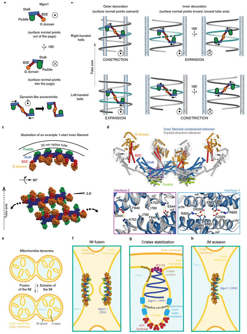
A dynamin-like power stroke would result in different remodelling processes depending on the assembly geometry of the Mgm1 filaments. When assembled on positively curved membranes in a left-handed helical pattern (Fig. 4), a dynamin-like power stroke would expand the diameter of the lipid tube. Conversely, a right-handed helix pattern would result in constriction as observed in dynamin (Extended Data Fig. 9a, b, Supplementary Video 1).
Mgm1 is the only known member of the dynamin superfamily that can assemble on the inside of membrane tubes, a membrane geometry similar to that of mitochondrial inner membrane cristae. We postulate that Mgm1 can form helical filaments at the inside of membrane tubes with the shape and dimensions of crista junctions (Extended Data Fig. 9c). Importantly, a power stroke in a left-handed helical assembly on the inside of membrane tube would constrict its diameter, as observed for the crista junctions upon OPA1 overexpression14, whereas a right-handed assembly would expand it (Extended Data Fig. 9a, b, Supplementary Video 1). In Extended Data Fig. 9e-h, we suggest how the membrane geometry of different filament assemblies might explain IM fusion, scission or stabilisation of cristae.
Taken together, our structural and functional studies reveal the molecular basis of Mgm1 assembly into filaments and models of how the rearrangements of these filaments induces remodelling of the inner mitochondrial membrane.
Methods
Protein expression and purification
Chaetomium thermophilum Mgm1 (Mgm1, amino acids 219-912) and indicated mutants of this construct were expressed from pET46-EK/LIC (Novagen) as N- terminal His6-tag fusion followed by a PreScission cleavage site. Proteins were expressed in Escherichia coli host strain BL21-DE3, and bacteria were cultured TB medium at 37 °C followed by induction with 200 μM Isopropyl-β-D-thiogalactopyranoside (IPTG) and a temperature shift to 20 °C for overnight expression. Seleno-methionine (SeMet) substituted Mgm1 was expressed in M9 minimal medium, supplemented with L-amino acids Lys, Phe, Thr (100 mg/l), Ile, Leu, Val, SeMet (50 mg/l), using the same vector and host strain as for native protein expression31. Cells were resuspended in buffer A (25 mM HEPES/NaOH (pH 7.8), 350 mM NaCl, 150 mM KCl, 2 mM MgC12, 1 μM DNase (Roche), 500 μM Pefabloc (Roth) and disrupted by a microfluidizer (Microfluidics). Cleared lysates (95,000 x g, 1 h, 4 °C) were incubated with Benzonase (Novagen) for at least 30 min at 4 °C prior to application to a Co2+-Talon column (Clontech). Protein were eluted with buffer A containing additional 100 mM imidazole. Fractions containing Mgm1 were incubated with 2.4 mM beta-mercaptoethanol (BME) and His6-tagged Prescission protease overnight at 4 °C. Using 50 kD molecular weight cut-off concentrators (Amicon), imidazole, BME and the free His-tag were removed by washing with buffer A, before a second application to a Co2+-Talon column to remove non-cleaved His-tagged Mgm1 and protease. The flow- through and four column volumes of washing buffer A were collected and concentrated. Finally, Mgm1 was purified by size exclusion chromatography on a Superdex200 column (GE) in buffer A. Fractions containing Mgm1 were pooled, concentrated and flash-frozen in liquid nitrogen (Extended Data Fig. 1a). SeMet substituted protein and mutants were purified using the same protocol.
Crystallisation and structure determination
Crystallisation trials by the sitting-drop vapour-diffusion method were performed at 4 °C using a Gryphon pipetting robot (Art Robbins Instruments) and Rock Imager storage system (Formulatrix). 300 nl of the seleno-methionine substituted Mgm1 at a concentration of 12.9 mg/ml was mixed with an equal volume of reservoir solution containing 8% PEG400, 3% isopropanol, 100 mM Na-citrate buffer (pH 5.5). Crystals appeared after 2 weeks and had final dimensions of 500 μM x 200 μM x 50 μM. During flash-cooling of the crystals in liquid nitrogen, a cryo-solution containing additionally 20% ethylene glycol was used. The dataset was recorded at BL14.1 at BESSY II, Berlin. One native dataset was collected at wavelength 0.9794 Å and 100 K temperature from a single crystal and processed and scaled using the XDS program suite32, 33. 22 out of 26 Se sites were detected by Autosol/PHENIX34 for 2 molecules in the asymmetric unit (80% solvent content). The density showed a continuous trace for the peptide backbone and clear anomalous signals for the positions of the seleno-methionine side chains. The initial model was built by adapting the BSE and stalk domain from the human dynamin 3 structure (5A3F) to the density. For chain A, the nucleotide-free G domain of human dynamin 1 (2AKA) fitted the density well, whereas density for the G domain of chain B was weak. The G domain was therefore omitted in the initial chain B model. The density for L2S and paddle showed well-ordered loop regions and helices. Missing residues in this area were built guided by the anomalous signal of the seleno-methionine side chains. The model was built using COOT35 and iteratively refined with Phenix 1.11.1-257536 including Hendrickson-Lattman coefficients, non-crystallographic symmetries of the respective domains, secondary structure restraints, one TLS group per domain and one B factor per amino acid. Occupancy of side chains with significant radiation damage was reduced to 0.8 or 0.6 for surface exposed glutamate or aspartate residues, and to 0.8 or 0.5 for seleno-methionine residues. Finally, the G domain from chain A was transplanted to chain B and refined as a rigid body. Two ethylene glycol molecules were built into remaining difference density at the end of the refinement. 1252 residues of 1304 refined residues (96%) are in the most favoured regions of the Ramachandran plot and 3 residues in the disallowed regions (0.23%), as analysed with Phenix. Buried surface areas were calculated using the PISA server37. Domain superpositions were performed with lsqkab from the CCP4 program suite38. Figures were prepared with the PyMol Molecular Graphics System, Version 2.0 (Schrödinger, LLC.). Sequences were aligned using CLUSTAL W39 and adjusted by hand.
Analytical ultracentrifugation experiments
All measurements were performed in 25 mM HEPES/NaOH pH 7.8, 50 mM NaCl, 150 mM KCl, 1 mM MgC12 at 20 °C using an Optima XL-A centrifuge (Beckman, Palo Alto, CA) and an An50Ti rotor equipped with double sector cells. Depending on protein concentration, the distribution of the protein in the cell was monitored at 230 or 280 nm. Data were analysed using the software SedFit40. Sedimentation velocity was run at 40,000 rpm for 3 h, sedimentation equilibrium was performed at 8,000 rpm.
Liposome co-sedimentation assays
Liposomes were prepared as previously described (www. endocytosis.org). 0.6 mg/ml Folch liposomes (total bovine brain lipids fraction I from Sigma) in 25 mM HEPES/NaOH (pH 7.8), 60 mM NaCl, 100 mM KCl, 0.5 mM MgC12 were incubated at room temperature with 4 μM of the indicated Mgm1 construct for 10 min in 40 μ1reaction volume, followed by a 210,000 x g spin for 10 min at 20 °C and SDS-PAGE analysis of the supernatant and the pellet. For quantification, the protein bands were integrated using ImageJ and the intensity of each band (supernatant or pellet) was divided by the sum of the intensities from supernatant and pellet.
Isothermal titration calorimetry
ITC experiments were performed at 18 °C in a PEAQ-ITC (Malvern) in 20 mM HEPES/NaOH pH 7.5, 60 mM NaCl, 100 mM KCL, 0.5 mM MgC12, with 50 μM Mgm1 in the reaction chamber and 1 mM GTPγS in the syringe. Malvern software was used to integrate the binding isotherms and calculate the binding parameters.
GTP hydrolysis assay
GTPase activities of 1 μM of the indicated Mgm1 constructs were determined at 37 °C in 25 mM HEPES/NaOH (pH 7.8), 60 mM NaCl, 100 mM KCl, 0.5 mM MgC12, in the absence and presence of 0.1 mg/ml Folch liposomes, using saturating concentrations of GTP as substrate (1 mM for the basal and 3 mM for the stimulated reactions). Reactions were initiated by the addition of protein to the reaction. At different time points, reaction aliquots were diluted 15-fold with GTPase buffer and quickly frozen in liquid nitrogen. Samples were analysed with an HPLC system (Agilent Technologies). Denatured proteins were adsorbed to a C18 guard column and nucleotides were separated via a reversed-phase Hypersil ODS-2 C18 column (250 x 4 mm), with 10 mM tetrabutylammonium bromide, 100 mM potassium phosphate (pH 6.5), 7.5% acetonitrile as running buffer. Nucleotides were detected by absorption at 254 nm and quantified by integration of the corresponding peaks. Rates were derived from a linear fit to the initial reaction.
Negative-stain electron microscopy
For electron microscopy of negatively stained samples in a Zeiss EM910, 4 μM Mgm1 (amino acids 219-912) in 25 mM HEPES-NaOH (pH 7.8), 60 mM NaCl, 100 mM KCl, 0.5 mM MgC12 and 3 mM guanosine-5'-[(β,γ)-methyleno]triphosphate were incubated at room temperature for 10 min. The final concentration of unfiltered Folch liposomes was 0.6 mg/ml. Samples were incubated on carbon-coated copper grids (Plano GmbH, Wetzlar, Germany) and stained with 2% uranyl acetate.
Yeast growth assay
To test the ability of mutant Mgm1 variants to complement the loss of wild-type Mgm1 in yeast (Saccharomyces cerevisiae), a GAL1 promoter was inserted upstream of the MGM1 open reading frame by homologous recombination. To this end, the GAL1 promoter was amplified from pFA6a-kanMX6 -PGAL141 (using oligos MGM1-PGAL-FW CATCCCAAGAGTGGCGAACTATAACACATTAGTAAGGATGgaattcgagctcgtttaaac and MGM1-PGAL-REV GCTGTCTTCTCAGAATTAAAAGCCGTACTGGGCTCGCATT cattttgagatccgggtttt42) and transformed into the YPH499 wild-type strain43. Mutations were introduced into pRS414 -Mgm144 by site-directed mutagenesis. The PGAL1-MGM1 yeast strain was transformed with the empty vector pRS414 or pRS414-Mgm1 encoding wild-type Mgm1 or mutant variants. After selection on synthetic defined (-TRP) media (0.67% [w/v] YNB without amino acids [BD Difco], – TRP amino acid drop-out mix [MP Biomedicals]) containing 2% [w/v] galactose and 1% [w/v] raffinose), yeast were grown in media containing 2% [w/v] glucose as carbon source to suppress expression of the endogenous wild-type Mgm1 allele. Under these conditions, cells expressing no or non-functional Mgm1 rapidly lose mitochondrial DNA6. Subsequently, cultures were diluted in media containing 0.2% [w/v] glucose in 48-well microtiter plates and growth was monitored for 24 h at 30 °C using a Tecan Spark 10M microplate reader by measuring the absorbance at 600 nm every 5 min after a 10 s linear shake with an amplitude of 2.5 mm at 630 rpm. Between cycles, the plate was agitated in a double-orbital shaker with an amplitude of 1.5 mm at 180 rpm. Blank-corrected mean absorbance values from two or three wells per mutant strain were plotted using GraphPad Prism 6.0 and growth experiments were repeated with cell populations from three independent yeast transformations.
To test for dominant-negative effects of Mgm1 mutants, the wild-type strain YPH499 was transformed with pRS414-Mgm1 encoding wild-type or mutant Mgm1 and growth was assessed in synthetic defined medium containing 3% [v/v] glycerol as described above. To test whether Mgm1 variants are stably expressed in yeast cells and able to retain mitochondrial DNA, mitochondria were isolated on a small scale45 and analysed by SDS-PAGE and Western blotting using antibodies directed against Mgm1, Cox1 (mitochondrially encoded cytochrome c oxidase subunit 1) and Ssc1 (mitochondrial Hsp70, loading control).
Yeast microscopy
Yeast cells were grown in synthetic defined (-TRP) media containing either 2% [w/v] glucose (for PGAL1-MGM1 yeast strains expressing plasmid-borne Mgm1 variants) or 3% [v/v] glycerol (for dominant-negative mutant strains) to mid-logarithmic phase and stained with 0.5 μg/ml DAPI (4',6-diamidino-2-phenylindole) and 175 nM DiOC6 (3,3'-dihexyloxacarbocyanine iodide) in 5% [w/v] glucose, 10 mM HEPES (pH 7.2). Immediately after staining, Z-stacks were recorded on a Leica DMi8 fluorescent microscope with a 63x/1.40 objective and a Leica DFC3000 G CCD camera. Images were deconvoluted with Huygens Essential (Scientific Volume Imaging, The Netherlands, http://svi.nl) and maximum intensity projections were created in Fiji46. Contrast was adjusted linearly to correct for variations in DiOC6 uptake. For quantification of mitochondrial morphology, cells with tubular or fragmented mitochondrial networks were counted in images from three independent cultures (for each culture at least 70 cells were counted). WT p0 cells were generated by ethidium bromide treatment of p+ cells.
Electron microscopy of yeast mitochondria
Yeast cells were fixed for 3h with 4% (w/v) paraformaldehyde, 0.5% (v/v) glutaraldehyde in 0.1M citrate buffer (pH and temperature adjusted to growth conditions). Samples were treated with 1% (w/v) sodium metaperiodate for 1 h at room temperature. Yeast cells were embedded in 10% (w/v) gelatin, infiltrated with 2.3M sucrose and frozen in liquid nitrogen. Ultrathin sections were cut at -115 °C (Reichert Ultracut S, Leica) and collected on 200 mesh copper grids (Plano) coated with formvar and carbon. Sections were stained with 3% (w/v) tungstosilicic acid hydrate in 2.5% (w/v) polyvinyl alcohol. Samples were examined at 80 kV with a Zeiss EM 910 electron microscope (Zeiss), and images were recorded with a Quemesa CDD camera and the iTEM software (Emsis GmbH). Images were analysed by ImageJ/Fiji. All applied statistical test were calculated with Prism (GraphPad software). Normality distribution test (Kolmogorov-Smirnov test) was carried out for all experimental values, and with normally distributed data, a Student t-Test (two-tailed P-value) was applied, otherwise the Mann-Withney-Rank-Sum (twotailed P-value) test was used to calculate the significant difference between two groups.
Liposome preparation for electron cryo-tomography
For examining Mgm1 assembly on membranes by electron cryo-tomography, dried lipids were rehydrated to a final concentration of 3 mg/ml in liposome buffer (20 mM HEPES, pH 7.5, 150 mM NaCl). Folch lipids (brain extract from bovine brain, type I, fraction I, Sigma-Aldrich) were used for inside decoration, or a lipid mixture of 70% galactocerebroside47, 10% cardiolipin (both Sigma-Aldrich) and 20% DOPC (Avanti Polar Lipids) for outside decoration of tubes. Liposomes were prepared by sonication plus extrusion through a 1 μm polycarbonate filter. Rehydrated lipids were incubated with purified Mgm1 (final concentration 10 μM) for 30 minutes at room temperature in the absence or presence of GTPγS (final concentration 1 mM, Jena Bioscience GmbH, Jena, Germany). For inside decoration, Mgm1 (+/- nucleotide) was added prior to the liposome preparation step.
Grid preparation and image acquisition for electron cryotomography
The final sample was mixed 1:1 with colloidal gold fiducial markers and 3 μ1were applied to freshly glow-discharged R2/2 Cu 300-mesh holey carbon-coated support grids (Quantifoil Micro Tools, Jena, Germany). Grids were plunge-frozen using a Vitrobot Mark IV plunge-freezer at 100% humidity and 10°C. Samples were imaged in a FEI Titan Krios electron microscope (FEI Company, Hillsboro, OR) operating at 300 kV, equipped with a K2 summit direct electron detector and Quantum energy filter (Gatan, Inc., Pleasanton, CA). The nominal magnification was set to 53,000x, yielding a calibrated pixel size of 2.7 Å. Tomographic tilt series were acquired following a dose-symmetric tilting scheme48 with a 3° increment and a cumulative total electron dose of approximately 90 e/Å2. Defocus values ranged from -2.0 to -4.0 |j,m. Data were acquired with the SerialEM software package49 in dose-fractionation mode.
Tomogram reconstruction and subtomogram averaging
Dosefractionated movies of tomograms were aligned using either Unblur50 or MotionCor251. After CTF-correction images were combined to generate a raw image stack that was used as input for generating tomograms with IMOD. Single tilt-images were aligned by gold fiducial markers and volumes reconstructed by weighted back-projection. Particle extraction, alignment and subtomogram averaging were performed with Dynamo52 and MATLAB. For a whole tube, particles were picked along the filaments using the respective option in the Dynamo toolbox. 18 membrane tubes covered with a clear visible protein coat within 15 different tomograms and 10 tubes within 10 tomograms were used for processing for the apo form and the GTPγS bound form, respectively. Due to the differences in diameter of the inside decoration, only two membrane tubes in two individual tomograms were used for the apo form as well as the GTPγS bound state. For close-up views, tubes were sub-boxed along the helical pattern. For tubes decorated on the inside, particles were picked along the wall of the lipid tube. Before subtomogram averaging, the datasets was divided into two independent half sets for resolution estimation. Each half set was aligned to an independent reference generated from a subset of each half set and reference-free alignment. To address the possibility of different handedness, classification was done during the processing workflow. Only protein assemblies with a left-handed helical pattern were observed. To exclude that the left-handed arrangement of the outside decoration was driven by the preformed lipid tubes, subtomogram averaging of Mgm1 covering the outside of Folch lipid tubes of different diameter was done. Also in this case, only protein assemblies with a left-handed helical pattern were observed. Numbers of particles contributing to the converged averages of the main structures and final resolution from FSC curves are listed in Extended Data Table. 2. The final structures were obtained using relion_reconstruct from the Relion toolbox. USCF Chimera and MATLAB were used for structure and FSC curve display, respectively53.
Molecular dynamics simulations
Flexible fitting into cryo-ET volume: A general approach for building atomic models from cryo-ET reconstructions is to include a potential energy term coupling the atomic coordinates during a molecular simulation to the experimentally determined density. Here, we used the MDfit method54, which employs an all-atom structure-based model (SBM)55 based on the tetramer crystal structure, and additionally includes an energetic term that attempts to maximise the correlation between the experimental density and the simulated density of the molecular dynamics trajectory. The SBM has an explicit energy minimum at the tetramer crystal structure, which means that the secondary structure seen in the crystal is maintained during flexible fitting. Modified Gromacs source code containing MDfit and software for creating the all-atom structure-based topologies are available for download at http://smog-server.org 55. Default MDfit parameters were used, including setting the energetic weight of the map equal to the number of atoms. For both the inner and outer decoration, the initial configuration was generated by manually placing twelve tetramers (247,728 heavy atoms) into and surrounding the cryo-ET volume with the aid of the “Fit in Map” tool in Chimera53. Simulations were performed until the cross-correlation stabilised. Only the dimers that were completely within the cryo-ET volume were saved for deposition alongside the cryo-ET volume. After fitting the inner decoration, G domains appeared to be in contact. This was checked by strongly constraining the G domains to form the G interface (as in dynamin). The fit including the constraint was nearly identical to that without, suggesting that the cryo-ET for the inner decoration contains the canonical G interface. The submitted model includes the constraint.
All-atom MD to support the “pre-shaped” tetramer and characterise its flexibility: A 2.6 microsecond all-atom molecular dynamics simulation of a stalk tetramer in explicit solvent was performed to estimate its shape in the absence of crystal interactions. The simulation was initialised from the tetramer crystal structure with a closed interface-1 and contained for each monomer the four stalk helices (residues 549-590, 635-720, and 828-877). Two G-G-S-G-G linkers were used to connect breaks in the stalk where the paddle was cut out, creating a single chain for each stalk monomer. Simulations were performed with Acellera ACEMD56 using the CHARMM36 forcefield57. Details of the simulation are as follows: NPT ensemble, temperature 300K, Langevin thermostat, Berendsen barostat at 1 atm, restrained bonds, timestep 4 fs, PME electrostatics, grid spacing 1 Å, cutoff 9 Å, switching at 7.5 Å. The conformation of the stalk tetramer was analysed to estimate the structural preference and flexibility of a stalk filament containing the tetramer. See Extended Data Fig. 7 for details.
All-atom structure-based model for inner decoration of 1-start helix: Our aim was to determine the tetramer structure upon confinement in a filament decorating the interior of a narrow membrane tube (r=30 nm) with a small pitch (p=12 nm). In particular, we were interested whether the crystallographic interfaces 1/2 can be consistent with negatively curved geometries. To this end, a molecular dynamics simulation was performed on a short filament (octamer) using a simplified potential that includes the all-atom geometry. Three constraints were imposed: 1) the putative membrane binding residues R748 and K749 in each monomer were constrained to a 30 nm radius from the z-axis, 2) an impenetrable cylindrical wall was imposed with a 30 nm radius, 3) the z coordinate of the centres of mass of each dimer (interface-2) were constrained such that the short filament had an effective pitch of 12 nm. No restraints were introduced in interface-1. The simulation potential was an all-atom structure-based model using the tetramer crystal structure with interface-1 formed. The simulation topology for Gromacs58 was created using the tetramer crystal and SMOG2.1 with the default forcefield “SBM_AA”55. The octamer topology was created by merging two tetramer topologies and additionally copying the requisite pair interactions for the new interface-1 created by connecting the tetramers. Langevin dynamics with a low temperature (0.16 reduced units, 20K Gromacs temperature) for 10x106 steps was used to get near to the minimum energy subject to the constraints. A steepest-descent minimisation was used for the final analysed configuration. To minimize edge effects, the interior tetramer of the octamer filament was analysed.
Tube pulling assays
Mgm1 was labelled with a fluorescein-labelled peptide using a sortase-mediated reaction59. All lipids were purchased from Avanti Polar Lipids, Alabaster, AL, USA. Giant Unilamellar Vesicles (GUVs) were electroformed24 from a lipid mix (2 mg/ml) containing Di-Oleyl-Phosphatidylcholine (DOPC), Di-Oleyl-Phosphatidylserine (DOPS), Rhodamine-phosphatidylethanolamine (Rhod-PE) and Di-Sialyl-Phosphatidylserine-Poly-ethylene-glycol-2000-biotin (DSPE-PEG(2000)Biotin), at a ratio of 7:3:0.01:0.003. GUVs were then transferred to a microscopy chamber of two rectangular glass slides (11x35 mm) and mounted on an inverted microscope including a Nikon eclipse Ti base, a CSU-X1 confocal system (Nikon, Tokyo, Japan), an Andor Ixon EMCCD camera (Oxford Instruments, Abingdon-on-Thames, UK) and a homemade optical tweezers consisting of a 5 W 1064 nm laser (ML5-CW-P-TKS-OTS, Manlight, Lannion, France) focused through a 100 x 1.3 NA oil objective. Images were acquired using SlideBook software (Intelligent Imaging Innovation). Bead traces were acquired with a C-MOS Camera (Picelink, Ottowa, Canada) using custom-made software. Outward membrane nanotubes were formed by holding a 3.05 μM streptavidin-coated polystyrene bead (Spherotech, Lake Forrest, IL, USA) glued onto a GUVs with optical tweezers, while pulling away the GUVs held by aspiration with a hand micropipette and controlled with motorised micromanipulators (MP-285, Sutter Instrument, Novato, CA, USA). Subsequently, Mgm1 was diluted to 3 μM final concentration in 20 mM HEPES/NaOH pH 7.4, 200 mM NaCl and 1 mM MgC12, and injected in the vicinity of the membrane tube using a second micropipette connected to a pressure control system (MFCS-VAC -69 mbar, Fluigent, Le Kremlin-Bicétre, France). For pulling membrane nanotubes inward, 2.01 μM glass beads (Bangs Laboratories, Fishers, IN, USA) were internalised with optical tweezers into GUVs adhering to an Avidin-coated flow chamber (coverslip and sticky-Slide VI 0.4, Ibidi, Germany). Tubes were pulled by moving the stage, and thus the GUV. 3 μM Mgm1 were added with a syringe pump (Aladdin, World Precision Instruments) connected to the Ibidi flow chamber. The force F was determined by applying Hooke’s law F= k*Δx to the bead displacement Δx and trap stiffness k (3.05 μM beads: k=79 pN/nm; 2.01 μM beads: k= 75 pN/nm). The basis of inward pulled tubes was unstable and moved on the surface of the GUV, so that the projection on the bead displacement in the X and Y axes changed rapidly. Furthermore, since the beads were pre-endocytosed into the GUVs, the initial position of the bead without force was unknown, compared to the outward tube pulling assay, where the bead position was recorded before it became attached to the GUV. Therefore, ΔF instead of F was plotted as it is more reliable. In Extended Data Fig. 8d, 6 μM Mgm1 was added to increase protein polymerization and therefore the force generated. In experiments requiring GTP, the buffer was supplemented with 2 mM GTP. The following settings were applied for Fig. 4c, Extended Data Fig. 8a, b: resolution: 512x512x10s, 145 nm/pxl, 16 bit; fluorochromes: Fluorescein (excitation: 488 nm, Bandpass filter 520/50, Dichroic Beamsplitter 405/488/568/647; LUT: Green (Fiji)) Rhodamine B (excitation: 561 nm, Bandpass filter 607/30, Dichroic Beamsplitter 405/488/568/647; LUT: Red (Fiji)); experiments were performed at room temperature in 20 mM HEPES/NaOH pH 7.4, 200 mM NaCl, 1 mM MgC12. For Fig. 5c, Extended Data Fig. 8c-d: resolution: 512x512x30s, 145 nm/pxl, 16 bit; fluorochromes and experimental conditions as above.
Extended Data
Extended Data Figure 1. Structure determination and analysis.
a, SDS-PAGE of recombinantly expressed and purified Mgm1: M – marker proteins, NI – whole-cell lysate, non-induced, I – whole-cell lysate, induced, R – whole-cell lysate, resuspended, harvested cells, D – whole-cell lysate, disrupted cells, CL – cleared lysate, FT – flow-through, W – buffer wash, PC – after Prescission protease cleavage, L – as loaded onto gel filtration column (n = 5 independent experiments). b, Selenium (Se) sites and experimental density at 1.4 σ before model building and refinement of G domain (top left), stalk (top right), BSE (bottom left) and paddle domain (bottom right). c, Ribbon diagram of Mgm1 dimer indicating positions of confirmed methionines in ball-and- stick presentation. Anomalous difference density contoured at 2.5 σ in magenta. An anomalous difference map was calculated from refined phases, resulting in discrete difference peaks indicating the positions of Se atoms. Four Se sites in the G domain, three in the BSE, two in the paddle domain and three in the stalk were used to determine the structure and verify the sequence assignment in the model. d, Mutations resulting in impaired lipid binding60 or in temperature-sensitive inner mitochondrial membrane fusion deficits10 were mapped onto the crystal structure. Mutations localise to the G interface, the G domain/BSE interface, stalk interface-1 or the paddle domain. e, Sequence conservation of nine Mgm1 sequences (see Supplementary Fig. 1 for alignments) was plotted on the surface of an Mgm1 monomer. Magenta – high conservation, cyan – low conservation. Residues investigated in this study are labelled and interfaces and contact sites circled.
Extended Data Figure 2. Comparison of Mgm1 and dynamin.
a, Monomers of Mgm1 (left) and dynamin (right) coloured by domain. b, G/BSE domains of nucleotide-free Mgm1 and dynamin (grey, pdb 5A3F) were superimposed on the BSE domains with a Cα root-mean-square deviation (rmsd) of 2.6 Å and 40% sequence identity. Both structures are in the closed state. The nucleotide-binding site is indicated. c, Superposition of the upper part of the stalk between Mgm1 and dynamin. In contrast to dynamin, the stalk in Mgm1 is kinked. d, Comparison between Mgm1 (left) and dynamin (right) stalk dimers. In both proteins, the dimer buries a total surface area of 1200 Å2. However, in Mgm1, interface-2 is shifted towards the paddle, resulting in a V-shaped dimer, whereas the dynamin dimer is X-shaped. e, Association of two dimers in the respective tetrameric crystal structures. In dynamin, assembly of dimers occurs via two interfaces (interface-1 and 3), whereas only interface-1 is present in Mgm1.
Extended Data Figure 3. Biochemical and negative-stain EM analysis.
a, Liposome binding assays (see also Fig. 1c and 2d) and quantification for Mgm1 mutants. Error bars indicate standard deviation of 4 independent measurements. b, Isothermal titration calorimetry experiments showing binding of GTPγS to Mgm1 with a Kd of 9 +/- 3 μM, binding number n=1.01, deviation represents rms error of the fit (n = 1). c, Sedimentation equilibrium of Mgm1 wild-type (black) and mutant F840D (red) was performed at a protein concentration of 1 mg/ml at 8,000 rpm and 20 °C. The protein distribution in the cell was monitored by absorbance at 280 nm. Solid lines represent fits to a molecular mass of Mr = 146 +/- 6 kDa for WT Mgm1 and 78 +/- 5 kDa for the F840D mutant (deviation represents rms error of the fit), indicating dimeric and monomeric association states at given conditions. The upper panel shows the original data and fits, the lower panels show the residuals from fit to data. d, GTPase assays using HPLC analysis. Error bars show standard deviation of the mean of 4 independent experiments (each with 4 or 5 data points). e, Control experiments for negative-stain EM analysis of Mgm1-mediated membrane remodelling. Scale bars: 200 nm. f, Mgm1 binds to liposomes and forms tubes of different diameters with or without nucleotides present. Scale bars: 100 nm. g, Representative electron micrographs for Mgm1 mutants. Mutations in dimer interface-2 (F840D), in the membrane-binding site (R748A, K749A), the disulphide bond in the paddle domain (C812S, C821S) or in the putative paddle-paddle contact (F779D, S780D) show severe defects in tube formation or in the assembly of a regular liposome decoration compared to Mgm1. Scale bars: 100 nm. n = 2 independent experiments for e-g.
Extended Data Figure 4. Yeast assays.
a, Schematic overview of yeast complementation experiments. In the presence of 2% glucose, expression of chromosomally encoded Mgm1 from the GAL1 promoter is suppressed. Yeast cells irreversibly lose the mitochondrial genome in the absence of Mgm1 (i.e. become ρ0) and cannot switch to respiratory growth upon glucose depletion (as shown by the shift from low glucose conditions to the oxidation of ethanol produced during fermentation of glucose). By co-expressing wild type yeast Mgm1 or the corresponding Mgm1 mutants, functionality of the Mgm1 variants is assessed through various rescue parameters. b, Representative growth curve for the unmodified yeast strain transformed with an empty vector (e.v.), the engineered yeast strain (PGALl-MGMI) complemented with yeast Mgm1 or an e.v. control (n = 3 independent experiments). c, Time-dependent expression of Mgm1, mitochondrially-encoded cytochrome c oxidase subunit 1 (Cox1) and the nuclear-encoded mitochondrial heat shock protein Ssc1 (loading control) was assessed by Western blot analysis of isolated mitochondria upon transfer of yeast cells from a glucose-rich to a glucose-depleted medium containing 2% ethanol as carbon source. = long and short isoform of Mgm1, ~ unspecific band, * Mgm1 degradation product (n = 2 independent experiments). Uncropped blots are shown in Supplementary Fig. 2. d, Western blot analysis of isolated mitochondria from PGALl-MGMI yeast grown in glucose-containing medium harboring plasmids that encode the respective mutant. (n = 3 independent experiments) e, f, Yeast growth complementation assays with Mgm1 mutants in the dimer interface and the paddle-paddle contacts. F805D in yeast corresponds to F840D in Chaetomium thermophilum and N675A corresponds to I700D. F779D/S780D in Chaetomium thermophilum corresponds to M745D/S746D in yeast. Representative growth curves (n = 3 independent experiments). Data in Fig. 3b and Extended Data Fig. 4e are derived from the same experiment, the controls are shown in all graphs as a reference. g, Mitochondrial morphology of the indicated yeast strains was assessed by fluorescence microscopy. DNA and mitochondria were stained with DAPI and DiOC6, respectively. Three representative images from n = 2 independent cultures are shown. Dimensions of the images are 7.5 μM x 7.5 μM. h, Overexpression of Mgm1 Y520A (tetramer interface mutant) leads to a strong dominant-negative effect on respiratory yeast growth (in media containing 3% glycerol as carbon source), representative growth curve (n = 3 independent experiments). i, Overexpression of Y520A leads to an only partial loss of mitochondrial DNA, as assayed by Cox1 expression. (n = 3 independent experiments) j, k, Overexpression of dominant-negative Mgm1 Y520A leads to a fragmentation of the mitochondrial network. Representative images and quantification of mitochondrial morphology in cells from n = 3 independent cultures, data displayed as mean ± s.d. l, Representative electron micrographs of yeast ultrathin sections assaying mitochondrial ultrastructure. Compared to mitochondria in wild-type (WT) yeast transformed with e.v. or pMgm1, mitochondria from cells expressing Mgm1-Y520A showed a significant loss of cristae and altered cristae shape, as indicated by an increased diameter of cristae junction and lumen and shorter cristae length. Scale bar: 70 nm. m, Quantification of cristae morphology. WT+pMgm1: nmito = 208, ncristae = 132; WT+e.v.: nmito = 201, ncristae = 135; WT+pMgm1-Y520A: nmito = 202, ncristae = 81; 2 independent experiments. *** P < 0.0001 (Gaussian approximation); Mann-Withney- U-test (two-sided, 95% confidence interval); cristae number graph represents mean +/- SEM: WT+pMgm1: (4.8 +/- 0.2) nm; WT+e.v.: (3.8 +/- 0.2) nm; WT+pMgm1-Y520A: (1.4 +/- 0.2) nm; cristae length graph represents mean +/- SEM: WT+pMgm1: (153 +/- 5) nm; WT+e.v.: (147 +/- 5) nm; WT+pMgm1-Y520A: (115 +/- 5) nm; cristae diameter graph represents mean +/- SEM: WT+pMgm1 junction: (19.9 +/- 0.5) nm; WT +e.v. junction: (21.0 +/- 0.5) nm; WT+pMgm1-Y520A junction: (26 +/- 1) nm; WT+pMgm1 tip: (24.7 +/- 0.6) nm; WT+e.v. tip: (25.8 +/- 0.7) nm; WT+pMgm1-Y520A tip: (35 +/- 2) nm.
Extended Data Figure 5. Cryo-ET analysis.
a, b, f, g, Electron micrographs on the left show one tomographic slice of each sample. The density map below obtained by subtomogram averaging are bandpass-filtered to the Fourier pixel value at 0.143 of the Fourier shell correlation (FSC) curve. The masked FSC curves of each subtomogram average is indicated with resolutions obtained at 0.5 and 0.143 FSC. a, Mgm1 on the outside of a galactocerebroside-containing lipid tube in the apo form. On the right, a larger box size was used for processing in order to visualize the complete protein coat decorating the lipid tube. b, Mgm1 in the GTPγS-bound form on the outside of galactocerebroside-containing lipid tubes are very similar to the apo form, whereas nucleotide-free and GMPPCP-bound conformations of dynamin assemble differently22. c, GTPase assays of Mgm1 in the presence of lipid tubes containing galactocerebroside, n=4, errors represent standard deviation from the mean. d, Low-resolution cryo-ET reconstructions of GTPγS-bound Mgm1 assembled on the outside of Folch membrane tubes of different diameters, as measured between bilayer centres. Based on the pitch angle θ and tube diameter d, the number of helical repeats (n-start) was estimated as n=2πrtanθ/h, where the filament radius r=d/2+4 nm and the width from paddle tip to tip h is 13 nm. While the basic filament architecture appears very similar, the filaments adapt their orientation to the curvature of the membrane tube. e, Representative electron micrographs showing Mgm1 coating the inner surface of a membrane tube (top) or both sides of the membrane tube (below). f, g, Cryo-ET reconstruction of Mgm1 in the apo and GTPγS-bound form on the inside of tubulated Folch liposomes, as in a, b. Grey scale bars: 10 nm; black scale bars: 100 nm.
Extended Data Figure 6. Mgm1 tetramers in crystal and membrane lattices.
Mgm1 assemblies in the presence of GTPγS on the outer (a, c) and inner surface (b, d) of a membrane tube. a, b, Surface representations of flexibly fitted Mgm1 molecules, showing their arrangement in the protein lattice. c, d, Fit into the corresponding cryo-ET volume. Note that the membrane density and, consequently, the paddle-membrane contact, is more prominent in the GTPγS-bound form compared to the nucleotide-free form (Fig. 4b, 5a). e, Comparison of Mgm1 tetramers in the crystal lattice (blue) with tetramers fitted to the subtomogram average volumes obtained for the external (orange) and internal surface lattice (pink). Fitting the paddle and the BSE / G domains required only minor rearrangements. f, Tetramers in the crystal lattice pack into a linear assembly. Crystal contacts between two tetramers are mediated by the BSE domain of one tetramer (blue) and the stalk domain of the neighbouring tetramer (grey), resulting in an open interface-1. When comparing intra- and intertetramer interactions, BSE domain residues E533, E534 and Y537 in α2B bind to different sites of the adjacent stalks.
Extended Data Figure 7. Molecular dynamics simulations.
a, Schematic of a 4-start helix. b, Mgm1 filaments in a 4-start helix, as in the cryo-ET volume on the outside of lipid tubes. The filament is defined as a continuous string of stalk domains connected by alternating interfaces-1 and 2. With this arrangement, filaments have a radius of 22 nm (axis to the centre of the stalk) and pitch of 54 nm. c, A string of dimers in contact through identical interfaces-1, as in the crystal structure, results in a left-handed helical arrangement with a large pitch, similar to the cryo-ET filament of the outside decoration. d, Snapshot of the stalk tetramer structure in the MD simulation box. Analysis of the stalk tetramer conformation in MD simulations gives information about the structural preferences of the filament in the absence of other domains. Geometrical parameters are drawn on the structure. d is the distance between the centres of mass of neighbouring dimers (marked as filled black circles). 95% of the variation in d is between 6.8 and 7.7 nm. ν1-ν4 are vectors pointing along each stalk monomer, defining angles θ 1, θ2, and θ2’ as shown. α is the net inplane rotation defined by ν2 x ν3, and is related to the local radius of curvature of a filament containing the tetramer. α can be simply written as a difference of the two interface angles, α=θ2-θ1, where positive/negative α implies positive/negative curvature; θ2 > θ1 results in positive curvature and θ2 < θ1 results in negative curvature. β is the relative rotation angle of one dimer relative to the next, which controls the pitch and, thus, the handedness of the helix. β is defined by the angle between the vectors ν1 x ν2 and ν3 x ν4 viewed along νf. νf is a unit vector in the direction of the filament defined by connecting the centres of mass of the two dimers. The elastic coordinates of a helical filament are the curvature Κ and the twist π Positive/negative Κ yields helices that bind to positive/negative membrane curvature. Κ and ρ can be approximately related to α and β, and the relations are indicated in the figure. e, Schematic of the curvature Κ and the twist π For helices with a low pitch, Κ is approximately the inverse radius of curvature (1/r). f, The angles θ 1, θ 2, and θ’ are plotted over a portion (2.8 μs out of a total of 12 μs) of the simulation period. g, Distributions of θ 1, θ 2, and θ 2’ over the whole simulation period. θ 2, and θ 2’ are, in principle, identical and the similarity of the distributions indicates sufficient sampling. In the crystal structure θ1=123° and θ 2/θ 2’=142°/144°. The flexibility of interface-1 and 2 is similar, as seen from the similar distribution widths. The peak of the θ1 distribution is centred on the parameters obtained for the crystal packing, whereas θ2/θ2’ is different, which may indicate that additional domain contacts present in the crystal stabilise a different configuration of interface-2. h, Using the relations shown in panel d, θ1 and θ2 at each snapshot are used to estimate the distribution of the curvature. The curvature distribution is centred near 0, which indicates that the stalk filament (at zero twist) prefers weakly curved or flat membranes. i, The angle β is plotted over a portion (2.8 μs out of a total of 12 μs) of the simulation period. j, The distributions of β and k, τ over the whole simulation period. A negative α or π indicates that the stalk filament prefers a left-handed twist, but right-handed twists are thermally accessible. Note that no significant correlation is seen between θ 1, θ 2/θ 2’, and β
Extended Data Figure 8. Mgm1 attachment to membranes of different curvature.
Tube pulling experiments, as described in Fig. 4d and 5c. Mgm1 was labelled with a fluorescein tag (green) and GUVs with Rhod-PE (red). Positive force is defined as pointing from the bead to the GUV. a, Tubes were pulled outward of single GUVs held by a micropipette (n = 8 independent experiments in the absence of GTP, n = 10 independent experiments in the presence of GTP). b, Representative time-lapse images of nucleation and growth of Mgm1 polymers on tubes pulled away from a GUV (right panels), and corresponding force measurements (left panels). c, Representative examples for tubes pulled into single GUVs adhering to the glass surface (n = 7 independent experiments in the absence of GTP, n = 7 independent experiments in the presence of GTP). d, Same as in b, but for tubes pulled into GUVs. ΔF is shown, as absolute forces were difficult to measure.
While Mgm1 covered the GUV surface in experiments c and d, it apparently did not oligomerize along the entire inward-pulled tube, as judged from the fluorescence signal. This likely reflects a decreased Mgm1 diffusion along the tube lumen. However, when the tube is not fully covered, a GTP-dependent shape change of the Mgm1 coat in the tube would not induce a force, as previously demonstrated for dynamin61. Therefore, the force increase likely results from the GTP-dependent remodelling of the Mgm1 coat on the GUV. In case of the outer decoration, Mgm1 oligomerizes on the tube and the GUV. In this case, the force increase can be caused by GTP-dependent alterations of the Mgm1 coat on the GUV and/or tube expansion. We note that these experiments gave no hint of GTP-driven constriction of membrane tubes.
Extended Data Figure 9. Model of Mgm1 action.
a, Based on the close similarity of Mgm1 and dynamin G domain/BSE (Extended Data Fig. 2b), we propose that Mgm1 and dynamin perform similar power strokes. G domain dimerization would link neighbouring Mgm1 filaments. The power stroke would then result in negative torque in the direction of the membrane normal. In b, the circle with a dot indicates vector towards the viewer and circle with an x indicates vector in the opposite direction. The arrow represents the direction of the torque. Note that power stroke torque is independent of membrane curvature and helix handedness. During the power stroke, the helix pitch remains constant because of the G domain contacts. Unwinding or winding of filaments then translates into a change in helix diameter. Inter-paddle contacts must be weak or absent as the filaments slide past each other. b, The power stroke torque applies an equal and opposite force between neighbouring turns. For outside decoration, the surface normal points outward. The resulting forces would constrict a right-handed helix and expand a left-handed helix. For inside decoration, the surface normal points inward, reversing the sign of the power stroke torque. This reverses the resultant forces on the filament, which would expand a right-handed helix and constrict a left-handed helix. See also Supplementary Video 1. c, Modelling an example helical Mgm1 filament on inner tube surface. While the Mgm1 tetramer on the inside lattice observed by cryo-ET resembled the crystal tetramer closely, formation of a continuous filament on the inside of a narrow tube would require curvature changes in the tetramer relative to the crystal structure. Using an all-atom structure-based model, we explore how the tetramer structure might change as part of a tight filament. The modelling parameters ensured that (1) a short filament (4 dimers) fits within the steric constraints of a 30 nm radius tube and (2) that the pitch results in a 1-start helix (left-handed pitch angle of 3.6°). Otherwise, the shape of the tetramer is free to find its optimal shape. Changes in the interface bending angles result in a transition from positive curvature (θ2>θ1) to negative curvature (θ2<θ1) (Extended Data Fig. 7d). d, Comparison of the constrained tetramer shown in c (central dimers) with the crystal structure. Minor changes in interface-1 and larger changes in interface-2 (with minimal changes to atomic packing, see insets) allow a conformational switch within the tetramer from binding to a concave surface (as in the crystal packing geometry) to binding to a convex surface. In this case, θ1=128° and θ2=117°. See also Extended Data Fig. 7g for comparison to explicit solvent simulations. e, Schematic overview of mitochondrial inner membrane remodelling. f-h, Models of mitochondrial membrane remodelling by Mgm1/OPA1 filaments. f, During IM fusion, Mgm1/OPA1 filaments may assemble on opposing membrane buds to stabilise the membrane curvature at the fusion site, as proposed in ref. 62. g, On the inner cristae surface, Mgm1/ OPA1 filaments may assemble into lefthanded helical filaments to constrict the cristae junction in a GTPase-dependent fashion. Alternatively, they may assemble into right-handed helical filaments that expand the cristae volume to prevent their collapse. In this way, Mgm1 filaments may counteract the membrane-constricting activity of the ATPase synthase dimers63 or the MICOS complex64-67 to pull lipids into cristae and allow the dynamic transition from a tight cristae state with reduced oxidative phosphorylation to an expanded active state with high oxidative phosphorylation activity. In agreement with this model, cristae have been shown to collapse when a GTPase-deficient OPA1 variant is expressed14. h, Similar to dynamin assemblies at the neck of clathrin-coated pits, Mgm1/OPA1 may assemble in a right-handed helix around the neck of an inner membrane junction, resulting in constriction and membrane scission upon GTP hydrolysis. The assembly geometry of the Mgm1/OPA1 filaments may depend on lipid composition, interaction partners or the specific Mgm1/OPA1 isoform. Supporting the latter assumption, IM fusion requires l-OPA1, but the s-OPA1 isoforms are sufficient for stabilising cristae membranes68.
Extended Data Table 1. Data collection and refinement statistics.
a, Data collection and refinement statistics for the crystallographic data. *Values in parentheses are for highest-resolution shell. The data was collected from a single crystal. b, Data collection and processing statistics for cryo-ET data.
| a Crystallographic data | |
|---|---|
| Mgm1, SeMet pdb code 6QL4 | |
| Data collection | |
| Space group | P4122, 1 dimer/ ASU |
| Cell dimensions | |
| a, b, c (Å) | 147.4, 147.4, 344.7 |
| α, β, γ (°) | 90, 90, 90 |
| Wavelength | 0.9794 (Å) |
| Resolution (Å)* | 3.60 (3.60-3.69) |
| Rsym* (%) | 22.0(184) |
| I / σI* | 8.0(1.1) |
| Completeness (%)* | 99.8 (98.4) |
| Redundancy | 6.7 |
| Refinement | |
| Resolution (Å) | 49.1 -3.6 |
| No. reflections | 44,814 |
| Rwork / Rfree | 24.4 / 125.2 |
| No. atoms | |
| Protein | 10,332 |
| Ligand/ion | 2 |
| Water | 0 |
| B-factors | |
| Protein | 212 Å2 |
| Ligand/ion | 101 Å2 |
| Water | - |
| R.m.s deviations | |
| Bond lengths (Å) | 0.004 |
| Bond angles (°) | 0.986 |
| b, Cryo-ET data | |||||
|---|---|---|---|---|---|
| Mgm1 +GTPγS Outside (EMDB-4585) |
Apo Mgm1 Outside (EMDB-4582) |
Apo Mgm1 Outside overall tube (EMDB-4584) |
Mgm1 +GTPγS Inside (EMDB-4586) |
Apo Mgm1 Inside (EMDB-4583) |
|
| Data collection and processing | |||||
| Magnification | 53,000 | 53,000 | 53,000 | 53,000 | 53,000 |
| Voltage(kV) | 300 | 300 | 300 | 300 | 300 |
| Electron exposure (e-/ (Å)2) | 90 – 100 | 90 – 100 | 90 – 100 | 90 – 100 | 90 – 100 |
| Per tomogram | |||||
| Defocus range (μm) | 2 - 4 | 2 - 4 | 2 - 4 | 2 - 4 | 2 - 4 |
| Pixel size (Å) | 2.7 | 2.7 | 2.7 | 2.7 | 2.7 |
| Symmetry imposed | No | No | No | No | No |
| Initial particle images (no.) | 71,884 | 12,440 | 2,214 | 4,751 | 1,874 |
| Final particle images (no.) | 9,471 | 11,474 | 1,677 | 1,820 | 1,792 |
| Map resolution (Å) | 14.7 | 14.7 | 20.4 | 18.8 | 20.6 |
| FSC threshold | 0.143 | 0.143 | 0.143 | 0.143 | 0.143 |
Supplementary Material
Acknowledgements
This project was supported by ERC grants MitoShape (ERC-2013-CoG-616024 to O.D.) and ScaleCell (ERC-CoG-772230 to F.N.), grants from the Deutsche Forschungsgemeinschaft (SFB958/A12 and SFB740/C07 to O.D. SFB958/A04 and SFB740/D07 to F.N., SFB894/A20 to M.v.d.L., IRTG1830 to M.v.d.L. and F.W., SFB807 to R.S.), the Max Planck Society, a Humboldt fellowship to J.N., a pre-doctoral fellowship of the Boehringer Ingelheim Fonds to F.W., a Sofja Kovalevskaja Award from the Alexander von Humboldt Foundation to M.K., and a DOC Fellowship of the Austrian Academy of Sciences to M.H.. We thank Yvette Roske for help with crystallographic data collection, structure solution and ITC measurements, Tobias Brandt for help and assistance in preparing cryo-EM samples, Deryck Mills for cryo-EM maintenance, Bettina Purfürst for support in the negative-stain EM analyses, Tobias Bock-Bierbaum for helpful comments on the manuscript, Erik Werner from Research Network Services Ltd., Berlin, Germany, for his careful work on the videos, Audrey Xavier for help with Mgm1 fluorescence labelling, and the entire BESSY team for generous support during data collection at beamlines BL14.1, BL14.2 or BL14.3.
Footnotes
Author contributions. K.F. designed the construct, grew the crystals and solved the structure. L.D. determined the cryo-ET reconstructions with support of A.M., R.S and M.K.; J.N. and. F.N. conducted and analysed molecular modelling and molecular dynamics simulations, F.W. and A.v.d.M performed yeast-growth assays and A.-K. P. the tube-pulling assay together with N.C.; J.N., F.W. and A.-K. P. contributed equally to this study. J.S. purified the protein and J.S. and K.F. carried out the liposome co-sedimentation and GTPase assays, H.L. performed the AUC assays. E. R. and M. H. grew initial crystals of related Mgm1 constructs; C.M. and S.K. analysed yeast mitochondria using EM; K.F., L.D., J.N., C.M., A.R., M.v.d.L., W.K. and O.D. designed research and interpreted structural data. K.F., L.D., J.N., M.v.d.L., W.K. and O.D. wrote the manuscript.
Competing interests. The authors declare no competing financial or non-financial interest.
Additional information.
Extended data is available for this paper.
Supplementary information is available for this paper.
Reprints and permission information is available at npg.nature.com/reprintsandpermissions.
Publisher’s note: Springer Nature remains neutral with regard to jurisdictional claims in published maps and institutional affiliations.
Data availability
The atomic coordinates of Mgm1 have been deposited in the Protein Data Bank with accession number 6QL4. Maps obtained by subtomogram averaging were deposited in the Electron Microscopy Data Bank with accession number EMD-4582, EMD-4584 for nucleotide-free Mgm1 on the outside of lipid tubes in a close-up view and the overall tube structure, respectively. EMD-4585 shows Mgm1 on the outside of a lipid tube in the GTPγS bound state. EMD-4583, EMD-4586 shows Mgm1 decorating the inside of a tube without and with GTPγS, respectively. All source data associated with the paper (beyond those deposited) are provided as supplementary information.
References
- 1.Nunnari J, Suomalainen A. Mitochondria: in sickness and in health. Cell. 2012;148:1145–1159. doi: 10.1016/j.cell.2012.02.035. S0092-8674(12]00235-8[pii] [DOI] [PMC free article] [PubMed] [Google Scholar]
- 2.Youle RJ, van der Bliek AM. Mitochondrial fission, fusion, and stress. Science. 2012;337:1062–1065. doi: 10.1126/science.1219855. [DOI] [PMC free article] [PubMed] [Google Scholar]
- 3.van der Laan M, Horvath SE, Pfanner N. Mitochondrial contact site and cristae organizing system. Curr Opin Cell Biol. 2016;41:33–42. doi: 10.1016/j.ceb.2016.03.013. [DOI] [PubMed] [Google Scholar]
- 4.Pernas L, Scorrano L. Mito-Morphosis: Mitochondrial Fusion, Fission, and Cristae Remodeling as Key Mediators of Cellular Function. Annu Rev Physiol. 2016;78:505–531. doi: 10.1146/annurev-physiol-021115-105011. [DOI] [PubMed] [Google Scholar]
- 5.Wai T, Langer T. Mitochondrial Dynamics and Metabolic Regulation. Trends Endocrinol Metab. 2016;27:105–117. doi: 10.1016/j.tem.2015.12.001. [DOI] [PubMed] [Google Scholar]
- 6.Jones BA, Fangman WL. Mitochondrial DNA maintenance in yeast requires a protein containing a region related to the GTP-binding domain of dynamin. Genes Dev. 1992;6:380–389. doi: 10.1101/gad.6.3.380. [DOI] [PubMed] [Google Scholar]
- 7.Alexander C, et al. OPA1, encoding a dynamin-related GTPase, is mutated in autosomal dominant optic atrophy linked to chromosome 3q28. Nat Genet. 2000;26:211–215. doi: 10.1038/79944. [DOI] [PubMed] [Google Scholar]
- 8.Delettre C, et al. Nuclear gene OPA1, encoding a mitochondrial dynamin-related protein, is mutated in dominant optic atrophy. Nat Genet. 2000;26:207–210. doi: 10.1038/79936. [DOI] [PubMed] [Google Scholar]
- 9.Wong ED, et al. The dynamin-related GTPase, Mgm1p, is an intermembrane space protein required for maintenance of fusion competent mitochondria. J Cell Biol. 2000;151:341–352. doi: 10.1083/jcb.151.2.341. [DOI] [PMC free article] [PubMed] [Google Scholar]
- 10.Meeusen S, et al. Mitochondrial inner-membrane fusion and crista maintenance requires the dynamin-related GTPase Mgm1. Cell. 2006;127:383–395. doi: 10.1016/j.cell.2006.09.021. S0092- 867406012141[pii] [DOI] [PubMed] [Google Scholar]
- 11.Cipolat S, Martins de Brito O, Dal Zilio B, Scorrano L. OPA1 requires mitofusin 1 to promote mitochondrial fusion. Proc Natl Acad Sci U S A. 2004;101:15927–15932. doi: 10.1073/pnas.0407043101. [DOI] [PMC free article] [PubMed] [Google Scholar]
- 12.Ishihara N, Fujita Y, Oka T, Mihara K. Regulation of mitochondrial morphology through proteolytic cleavage of OPA1. EMBO J. 2006;25:2966–2977. doi: 10.1038/sj.emboj.7601184. [DOI] [PMC free article] [PubMed] [Google Scholar]
- 13.Meeusen S, McCaffery JM, Nunnari J. Mitochondrial fusion intermediates revealed in vitro. Science. 2004;305:1747–1752. doi: 10.1126/science.1100612. [DOI] [PubMed] [Google Scholar]
- 14.Frezza C, et al. OPA1 controls apoptotic cristae remodeling independently from mitochondrial fusion. Cell. 2006;126:177–189. doi: 10.1016/j.cell.2006.06.025. S009286740600810-5 [pii] [DOI] [PubMed] [Google Scholar]
- 15.Yamaguchi R, et al. Opa1-mediated cristae opening is Bax/Bak and BH3 dependent, required for apoptosis, and independent of Bak oligomerization. Mol Cell. 2008;31:557–569. doi: 10.1016/j.molcel.2008.07.010. [DOI] [PMC free article] [PubMed] [Google Scholar]
- 16.Anand R, et al. The i-AAA protease YME1L and OMA1 cleave OPA1 to balance mitochondrial fusion and fission. J Cell Biol. 2014;204:919–929. doi: 10.1083/jcb.201308006. [DOI] [PMC free article] [PubMed] [Google Scholar]
- 17.Faelber K, et al. Crystal structure of nucleotide-free dynamin. Nature. 2011;477:556–560. doi: 10.1038/nature10369. nature10369 [pii] [DOI] [PubMed] [Google Scholar]
- 18.Ford MG, Jenni S, Nunnari J. The crystal structure of dynamin. Nature. 2011;477:561–566. doi: 10.1038/nature10441. nature10441 [pii] [DOI] [PMC free article] [PubMed] [Google Scholar]
- 19.Chappie JS, Acharya S, Leonard M, Schmid SL, Dyda FG. domain dimerization controls dynamin’s assembly-stimulated GTPase activity. Nature. 2010;465:435–440. doi: 10.1038/nature09032. [DOI] [PMC free article] [PubMed] [Google Scholar]
- 20.Ingerman E, et al. Dnml forms spirals that are structurally tailored to fit mitochondria. J Cell Biol. 2005;170:1021–1027. doi: 10.1083/jcb.200506078. [DOI] [PMC free article] [PubMed] [Google Scholar]
- 21.Ban T, Heymann JA, Song Z, Hinshaw JE, Chan DC. OPA1 disease alleles causing dominant optic atrophy have defects in cardiolipin-stimulated GTP hydrolysis and membrane tubulation. Hum Mol Genet. 2010;19:2113–2122. doi: 10.1093/hmg/ddq088. ddq088 [pii] [DOI] [PMC free article] [PubMed] [Google Scholar]
- 22.Kong L, et al. Cryo-EM of the dynamin polymer assembled on lipid membrane. Nature. 2018;560:258–262. doi: 10.1038/s41586-018-0378-6. [DOI] [PMC free article] [PubMed] [Google Scholar]
- 23.Reubold TF, et al. Crystal structure of the dynamin tetramer. Nature. 2015;525:404–408. doi: 10.1038/nature14880. nature14880 [pii] [DOI] [PubMed] [Google Scholar]
- 24.Chiaruttini N, et al. Relaxation of Loaded ESCRT-III Spiral Springs Drives Membrane Deformation. Cell. 2015;163:866–879. doi: 10.1016/j.cell.2015.10.017. [DOI] [PMC free article] [PubMed] [Google Scholar]
- 25.Gao S, et al. Structure of myxovirus resistance protein a reveals intra- and intermolecular domain interactions required for the antiviral function. Immunity. 2011;35:514–525. doi: 10.1016/j.immuni.2011.07.012. S1074-76131100369-4 [pii] [DOI] [PubMed] [Google Scholar]
- 26.Frohlich C, et al. Structural insights into oligomerization and mitochondrial remodelling of dynamin 1-like protein. EMBO J. 2013;32:1280–1292. doi: 10.1038/emboj.2013.74. emboj201374 [pii] [DOI] [PMC free article] [PubMed] [Google Scholar]
- 27.Kalia R, et al. Structural basis of mitochondrial receptor binding and constriction by DRP1. Nature. 2018;558:401–405. doi: 10.1038/s41586-018-0211-2. [DOI] [PMC free article] [PubMed] [Google Scholar]
- 28.Chappie JS, et al. A pseudoatomic model of the dynamin polymer identifies a hydrolysis-dependent powerstroke. Cell. 2011;147:209–222. doi: 10.1016/j.cell.2011.09.003. S0092-86741101015-4 [pii] [DOI] [PMC free article] [PubMed] [Google Scholar]
- 29.Roux A, Uyhazi K, Frost A, De Camilli P. GTP-dependent twisting of dynamin implicates constriction and tension in membrane fission. Nature. 2006;441:528–531. doi: 10.1038/nature04718. [DOI] [PubMed] [Google Scholar]
- 30.Antonny B, et al. Membrane fission by dynamin: what we know and what we need to know. EMBO J. 2016;35:2270–2284. doi: 10.15252/embj.201694613. [DOI] [PMC free article] [PubMed] [Google Scholar]
- 31.Doublie S. Preparation of selenomethionyl proteins for phase determination. Methods Enzymol. 1997;276:523–530. [PubMed] [Google Scholar]
- 32.Kabsch W. XDS. Acta Cryst D. 2010;66:125–132. doi: 10.1107/S0907444909047337. S0907444909047337 [pii] [DOI] [PMC free article] [PubMed] [Google Scholar]
- 33.Sparta KM, Krug M, Heinemann U, Mueller U, Weiss MS. Xdsapp2.0. J Appl Cryst. 2016;49:1085–1092. doi: 10.1107/S1600576716004416. [DOI] [Google Scholar]
- 34.Terwilliger TC, et al. Decision-making in structure solution using Bayesian estimates of map quality: the PHENIX AutoSol wizard. Acta Cryst D. 2009;65:582–601. doi: 10.1107/S0907444909012098. [DOI] [PMC free article] [PubMed] [Google Scholar]
- 35.Emsley P, Cowtan K. Coot: model-building tools for molecular graphics. Acta Cryst D. 2004;60:2126–2132. doi: 10.1107/S0907444904019158. [DOI] [PubMed] [Google Scholar]
- 36.Echols N, et al. Graphical tools for macromolecular crystallography in PHENIX. J Appl Cryst. 2012;45:581–586. doi: 10.1107/S0021889812017293. [DOI] [PMC free article] [PubMed] [Google Scholar]
- 37.Krissinel E, Henrick K. Inference of macromolecular assemblies from crystalline state. J Mol Biol. 2007;372:774–797. doi: 10.1016/j.jmb.2007.05.022. [DOI] [PubMed] [Google Scholar]
- 38.Winn MD, et al. Overview of the CCP4 suite and current developments. Acta Cryst D. 2011;67:235–242. doi: 10.1107/s0907444910045749. [DOI] [PMC free article] [PubMed] [Google Scholar]
- 39.Sievers F, Higgins DG. Clustal omega. Curr Protoc Bioinformatics. 2014;48:3 13 11–16. doi: 10.1002/0471250953.bi0313s48. [DOI] [PubMed] [Google Scholar]
- 40.Schuck P. Size-distribution analysis of macromolecules by sedimentation velocity ultracentrifugation and lamm equation modeling. Biophys J. 2000;78:1606–1619. doi: 10.1016/S0006-34950076713-0. [DOI] [PMC free article] [PubMed] [Google Scholar]
- 41.Longtine MS, et al. Additional modules for versatile and economical PCR-based gene deletion and modification in Saccharomyces cerevisiae. Yeast. 1998;14:953–961. doi: 10.1002/(SICI)1097-006(1199807)14:10<953::AID-YEA293>3.0.C0;2-U. [DOI] [PubMed] [Google Scholar]
- 42.Yofe I, Schuldiner M. Primers-4-Yeast: a comprehensive web tool for planning primers for Saccharomyces cerevisiae. Yeast. 2014;31:77–80. doi: 10.1002/yea.2998. [DOI] [PubMed] [Google Scholar]
- 43.Sikorski RS, Hieter PA. system of shuttle vectors and yeast host strains designed for efficient manipulation of DNA in Saccharomyces cerevisiae. Genetics. 1989;122:19–27. doi: 10.1093/genetics/122.1.19. [DOI] [PMC free article] [PubMed] [Google Scholar]
- 44.Ieva R, et al. Mgr2 functions as lateral gatekeeper for preprotein sorting in the mitochondrial inner membrane. Mol Cell. 2014;56:641–652. doi: 10.1016/j.molcel.2014.10.010. [DOI] [PubMed] [Google Scholar]
- 45.Morgenstern M, et al. Definition of a High-Confidence Mitochondrial Proteome at Quantitative Scale. Cell Rep. 2017;19:2836–2852. doi: 10.1016/j.celrep.2017.06.014. [DOI] [PMC free article] [PubMed] [Google Scholar]
- 46.Schindelin J, et al. Fiji: an open-source platform for biological-image analysis. Nat Methods. 2012;9:676–682. doi: 10.1038/nmeth.2019. [DOI] [PMC free article] [PubMed] [Google Scholar]
- 47.Wilson-Kubalek EM, Brown RE, Celia H, Milligan RA. Lipid nanotubes as substrates for helical crystallization of macromolecules. Proc Natl Acad Sci U S A. 1998;95:8040–8045. doi: 10.1073/pnas.95.14.8040. [DOI] [PMC free article] [PubMed] [Google Scholar]
- 48.Hagen WJH, Wan W, Briggs JAG. Implementation of a cryo-electron tomography tilt-scheme optimized for high resolution subtomogram averaging. J Struct Biol. 2017;197:191–198. doi: 10.1016/j.jsb.2016.06.007. [DOI] [PMC free article] [PubMed] [Google Scholar]
- 49.Mastronarde DN. Automated electron microscope tomography using robust prediction of specimen movements. J Struct Biol. 2005;152:36–51. doi: 10.1016/j.jsb.2005.07.007. [DOI] [PubMed] [Google Scholar]
- 50.Grant T, Grigorieff N. Measuring the optimal exposure for single particle cryo-EM using a 2.6 A reconstruction of rotavirus VP6. Elife. 2015;4:e06980. doi: 10.7554/eLife.06980. [DOI] [PMC free article] [PubMed] [Google Scholar]
- 51.Zheng SQ, et al. MotionCor2: anisotropic correction of beam-induced motion for improved cryo-electron microscopy. Nat Methods. 2017;14:331–332. doi: 10.1038/nmeth.4193. [DOI] [PMC free article] [PubMed] [Google Scholar]
- 52.Castano-Diez D, Kudryashev M, Arheit M, Stahlberg H. Dynamo: a flexible, user- friendly development tool for subtomogram averaging of cryo-EM data in high- performance computing environments. J Struct Biol. 2012;178:139–151. doi: 10.1016/j.jsb.2011.12.017. [DOI] [PubMed] [Google Scholar]
- 53.Pettersen EF, et al. UCSF Chimera--a visualization system for exploratory research and analysis. J Comput Chem. 2004;25:1605–1612. doi: 10.1002/jcc.20084. [DOI] [PubMed] [Google Scholar]
- 54.Whitford PC, et al. Excited states of ribosome translocation revealed through integrative molecular modeling. Proc Natl Acad Sci U S A. 2011;108:18943–18948. doi: 10.1073/pnas.1108363108. [DOI] [PMC free article] [PubMed] [Google Scholar]
- 55.Noel JK, et al. SMOG 2: A Versatile Software Package for Generating Structure-Based Models. PLoS Comput Biol. 2016;12:e1004794. doi: 10.1371/journal.pcbi.1004794. [DOI] [PMC free article] [PubMed] [Google Scholar]
- 56.Harvey MJ, De Fabritiis G. AceCloud: Molecular Dynamics Simulations in the Cloud. J Chem Inf Model. 2015;55:909–914. doi: 10.1021/acs.jcim.5b00086. [DOI] [PubMed] [Google Scholar]
- 57.Best RB, et al. Optimization of the additive CHARMM all-atom protein force field targeting improved sampling of the backbone phi, psi and side-chain chi 1 and chi 2 dihedral angles. J Chem Theory Comput. 2012;8:3257–3273. doi: 10.1021/ct300400x. [DOI] [PMC free article] [PubMed] [Google Scholar]
- 58.Pronk S, et al. GROMACS 4.5: a high-throughput and highly parallel open source molecular simulation toolkit. Bioinformatics. 2013;29:845–854. doi: 10.1093/bioinformatics/btt055. [DOI] [PMC free article] [PubMed] [Google Scholar]
- 59.Theile CS, et al. Site-specific N-terminal labeling of proteins using sortase-mediated reactions. Nat Protoc. 2013;8:1800–1807. doi: 10.1038/nprot.2013.102. [DOI] [PMC free article] [PubMed] [Google Scholar]
- 60.Meglei G, McQuibban GA. The dynamin-related protein Mgm1p assembles into oligomers and hydrolyzes GTP to function in mitochondrial membrane fusion. Biochemistry. 2009;48:1774–1784. doi: 10.1021/bi801723d. [DOI] [PubMed] [Google Scholar]
- 61.Roux A, et al. Membrane curvature controls dynamin polymerization. Proc Natl Acad Sci U S A. 2010;107:4141–4146. doi: 10.1073/pnas.0913734107. 0913734107 [pii] [DOI] [PMC free article] [PubMed] [Google Scholar]
- 62.Rujiviphat J, et al. Mitochondrial Genome Maintenance 1 (Mgm1) Protein Alters Membrane Topology and Promotes Local Membrane Bending. J Mol Biol. 2015;427:2599–2609. doi: 10.1016/j.jmb.2015.03.006. [DOI] [PubMed] [Google Scholar]
- 63.Muhleip AW, et al. Helical arrays of U-shaped ATP synthase dimers form tubular cristae in ciliate mitochondria. Proc Natl Acad Sci U S A. 2016;113:8442–8447. doi: 10.1073/pnas.1525430113. [DOI] [PMC free article] [PubMed] [Google Scholar]
- 64.Tarasenko D, et al. The MICOS component Mic60 displays a conserved membrane- bending activity that is necessary for normal cristae morphology. J Cell Biol. 2017;216:889–899. doi: 10.1083/jcb.201609046. [DOI] [PMC free article] [PubMed] [Google Scholar]
- 65.Barbot M, et al. Mic10 oligomerizes to bend mitochondrial inner membranes at cristae junctions. Cell Metab. 2015;21:756–763. doi: 10.1016/j.cmet.2015.04.006. [DOI] [PubMed] [Google Scholar]
- 66.Bohnert M, et al. Central role of Mic10 in the mitochondrial contact site and cristae organizing system. Cell Metab. 2015;21:747–755. doi: 10.1016/j.cmet.2015.04.007. [DOI] [PubMed] [Google Scholar]
- 67.Hessenberger M, et al. Regulated membrane remodeling by Mic60 controls formation of mitochondrial crista junctions. Nature Comm. 2017;8:15258. doi: 10.1038/ncomms15258. [DOI] [PMC free article] [PubMed] [Google Scholar]
- 68.Lee H, Smith SB, Yoon Y. The short variant of the mitochondrial dynamin OPA1 maintains mitochondrial energetics and cristae structure. J Biol Chem. 2017;292:7115–7130. doi: 10.1074/jbc.M116.762567. [DOI] [PMC free article] [PubMed] [Google Scholar]
Associated Data
This section collects any data citations, data availability statements, or supplementary materials included in this article.
Supplementary Materials
Data Availability Statement
The atomic coordinates of Mgm1 have been deposited in the Protein Data Bank with accession number 6QL4. Maps obtained by subtomogram averaging were deposited in the Electron Microscopy Data Bank with accession number EMD-4582, EMD-4584 for nucleotide-free Mgm1 on the outside of lipid tubes in a close-up view and the overall tube structure, respectively. EMD-4585 shows Mgm1 on the outside of a lipid tube in the GTPγS bound state. EMD-4583, EMD-4586 shows Mgm1 decorating the inside of a tube without and with GTPγS, respectively. All source data associated with the paper (beyond those deposited) are provided as supplementary information.


