Abstract
In airliner cabins, mixing ventilation systems with gaspers are not efficient in controlling contaminant transport. To improve the cabin environment, this investigation proposed an innovative ventilation system that would reduce contaminant transport and maintain thermal comfort. We manufactured and installed the proposed ventilation system in an occupied seven-row, single-aisle aircraft cabin mockup. Air velocity, air temperature, and contaminant distribution in the cabin mockup were obtained by experimental measurements. The investigation used the experimental data to validate the results of CFD simulation. The validated CFD program was then used to study the impact of the locations and number of exhausts on contaminant removal and thermal comfort in a one-row section of a fully occupied Boeing-737 cabin. Although the diffusers in the proposed system were close to the passengers' legs, the air velocity magnitude was acceptable in the lower part of the cabin and the leg area. The proposed system provided an acceptable thermal environment in the cabin, although passengers could feel cold when placing their legs directly in front of the diffusers. The four-exhaust configuration of the new ventilation system was the best, and it decreased the average exposure in the cabin by 57% and 53%, respectively, when compared with the mixing and displacement ventilation systems.
Keywords: Computational fluid dynamics (CFD), Contaminant transport, Mixing ventilation, Displacement ventilation, Air supply diffuser
Highlights
-
•
An innovative ventilation system for airliner cabins was proposed.
-
•
The system was manufactured and installed in an aircraft cabin mockup.
-
•
The system was optimized and assessed.
1. Introduction
The transmission of airborne infectious diseases, such as influenza [1], tuberculosis [2], and severe acute respiratory syndrome [3], has been observed in commercial airliners. As more and more people travel by air [4], it has become crucial to improve cabin air quality. There is a strong association between cabin air distribution and the transmission of airborne infectious diseases [5]. Therefore, it is important to investigate the air distribution in airliner cabins in order to improve the quality of cabin air.
Mixing ventilation systems are prevalently used to control the cabin environment in commercial airliners. A mixing ventilation system supplies clean air through diffusers on the ceiling and then removes the cabin air through exhaust slots on the side walls near the floor. A system of gaspers, which are small, circular, and adjustable vents above the seats, is also installed in most commercial airliners as a personalized ventilation system. The gaspers supply air directly to the passengers and are adjustable for flow rate and direction.
To investigate the air distribution in a cabin, several experimental studies have been carried out. For example, Liu et al. [6] used a combination of hot-sphere anemometers and ultrasonic anemometers (UAs) to obtain accurate velocity profiles at the diffusers and the velocity field in the first-class cabin of a functional MD-82 commercial airliner. They found that UAs could be used to accurately measure the distributions of three-dimensional airflow parameters. However, the UA sensor was too bulky for use in small areas. Cao et al. [7] performed a large-scale particle image velocimetry (PIV) measurement to characterize the mixing air distributions inside a partially transparent airliner cabin mockup. They obtained high-accuracy 2-D airflow information and found that the cabin airflows were of low velocity and high turbulence level. Li et al. [8] measured the distributions of air velocity, temperature, and tracer-gas (sulfur hexafluoride or SF6) concentration in the economy-class cabin of an MD-82 airplane with gaspers on and off. The experimental results showed that gaspers in a cabin with mixing ventilation might not be useful for improving cabin air quality, even though the gaspers seemed to supply clean air directly to passengers.
In addition to experimental studies, several investigations have modeled the air distribution in an airliner cabin with the use of computational fluid dynamics (CFD). For instance, Zhang et al. [9] employed the RNG k-ε model to simulate the CO2 distribution in a section of a Boeing 767 airliner cabin. They found that the CO2 concentration with the mixing air distribution was fairly uniform, and the mixing air distribution system could spread infectious diseases. You et al. [10,11] developed a consolidated turbulence model and a simplified gasper geometry model in a CFD program for predicting the airflow and contaminant transport in a cabin with gaspers. The CFD program was then used to investigate the impact of the gaspers on contaminant transport in the economy-class cabins of Boeing 767 and 737 airliner. It was found that the statistical impact of the gaspers on passengers' exposure to contaminants was neutral. Hence, the gaspers did not improve the cabin environment.
The literature review indicated that the current air distribution in airliner cabins cannot effectively control the transport of airborne infectious disease viruses. Meanwhile, displacement ventilation systems have been widely used in buildings and have been shown to be more effective than mixing ventilation systems in removing contaminants [12]. Therefore, to reduce the transmission of airborne infectious disease viruses and/or to improve cabin air quality, new ventilation systems have been developed further from the displacement ventilation system. Schmidt et al. [13] and Müller et al. [14] compared mixing ventilation displacement ventilation systems in a section of an A320 cabin mockup. Schmidt et al. [13] found that a mixing ventilation system had higher draft risk, while a displacement ventilation system could result in “hot heads.” However, Müller et al. [14] suggested that a displacement ventilation system could maintain an acceptable cabin thermal environment as long as the temperature difference between the head and feet was kept in a comfortable range. Bosbach et al. [15] measured the air velocity and temperature in a single-aisle airliner cabin with mixing ventilation, displacement ventilation, and hybrid ventilation during stationary ground and flight tests in an A-320 airliner. The displacement ventilation system supplied air through the lower sidewalls of the cabin and exhausted the air near the cabin ceiling, while the hybrid ventilation was a combination of mixing and displacement ventilation. The researchers found that the mixing ventilation system had the lowest heat removal efficiency, indicating that mixing ventilation may not be efficient in controlling contaminant transport. The use of a displacement ventilation system in a cabin, meanwhile, may be efficient in controlling the contaminant transport but, it may result in poor thermal comfort.
To improve the cabin air environment, this investigation proposed an innovative ventilation system that would reduce contaminant transport and maintain thermal comfort. The proposed ventilation system was manufactured and then installed in a fully occupied seven-row, single-aisle airliner cabin mockup. The air velocity, air temperature, and contaminant distributions in the cabin mockup were measured to confirm the performance of the ventilation system. This investigation also used a validated CFD program to obtain suitable parameters for the system by designing a cabin environment for a one-row section of a fully occupied Boeing-737 cabin. Finally, the CFD results were used to assess the proposed system.
2. The new ventilation system
We proposed a new ventilation system, as shown in Fig. 1 , which would maintain thermal comfort and reduce airborne contaminant transport in airliner cabins. Individual diffusers installed on the floor under the seats would supply clean air to the passengers in the row behind, and the cabin air would be extracted at ceiling level. Such a system would not occupy much of the passengers' leg room, since the diffusers would be installed between passengers or at the ends of the rows. Clean air would first be supplied directly to the passengers, who generate heat. In the presence of thermal plumes, the air would then travel upward, carrying exhaled contaminants from the passengers to the exhausts. Therefore, the system could reduce airborne contaminant transport in comparison with traditional mixing ventilation. The passengers' feet would not be in front of the diffusers, and thus the system would not produce a draft that would jeopardize cabin thermal comfort. The system combines the advantages of under-floor air distribution and displacement ventilation.
Fig. 1.
Schematic of the proposed ventilation system: (a) individual diffusers under the seats and (b) the positions of the diffusers and the air supply directions.
3. Measured and simulated air distributions for the new system
3.1. Experimental measurements
We manufactured the new ventilation system and installed it in a fully occupied, full-scale, single-aisle, cabin mockup as shown in Fig. 2 (a). The cabin had seven rows, each with six seats. The supply air temperature from the diffusers was controlled at 21 ± 1 °C. The exhaust was located in the center of the ceiling as shown in Fig. 2(b). Heated manikins were used to simulate passengers inside the cabin, and the power input to each of the manikins was 72 W. This cabin mockup was in an air-conditioned room that was maintained at 19 °C. The cabin wall surfaces were not insulated.
Fig. 2.
(a) Photograph and (b) schematic of the fully-occupied seven-row cabin mockup.
A constant-injection tracer-gas technique was used to measure the flow rate for each diffuser. This experiment used a mixture of 1% sulfur hexafluoride (SF6) and 99% N2 as the tracer gas. The mixture was injected into each diffuser at a flow rate of 140 L/h, and the SF6 concentration was measured at the outlet of an extended air hood connected with the diffuser. Therefore, the air flow rate for the diffuser was determined by:
| (1) |
where Qsupply is the diffuser flow rate, the SF6 injection flow rate, and C the measured SF6 concentration.
An infrared camera was used to measure the surface temperatures of the manikins, divided into five sections: head, chest, abdomen, thighs, and calves. Since the cabin walls were not insulated, surface temperatures were also measured, by the infrared camera and thermocouples, at the floor, aisle, sidewalls, side ceilings, and ceiling center, in each row.
This investigation measured air velocity, air temperature, and contaminant (tracer-gas) distributions in the cross section through the heated manikins in the fourth row (CS4). For the air velocity distribution, we used a PIV system and UAs. In the PIV measurements, a laser generator shined a laser sheet into the fourth row of the cabin mockup through the left side, and the camera was fixed In front of the second row to take high-resolution pictures. Note that the manikins in seats 2B, 3B, 2E, and 3E were removed to make room for the camera. The measuring area for each zone was 115 cm wide and 80 cm high, as shown in Fig. 3 (a). For each zone, images were collected for a period of 5 min at a frequency of 3 Hz after the cabin airflow had stabilized. The recorded images were processed and analyzed using the signal processing and cross-correlation techniques in the DynamicStudios software program to obtain the two-dimensional airflow field.
Fig. 3.
(a) PIV measuring area and (b) locations of the sampling points for the UAs in cross section CS4.
Fig. 3(b) shows the sampling points for the UA measurements. The air velocity distribution in CS4 was measured at a 0.15 m interval as represented by black dots. For measurement of the air distribution in the passengers' leg area, the section was shifted forward by 0.15 m to avoid the legs. The area in which the shifting occurred is indicated by red dots in Fig. 3(b). The total number of sampling points was 197, and the measurement of air velocity at each point lasted for 5 min at 20 Hz.
As shown in Fig. 4 (a), the air temperature distribution in CS4 was measured by thermocouples at an interval of 0.1 m. There were 426 sampling points for the air temperature measurements, and the data was collected at each point for 5 min at 1 Hz. The thermocouples were also used to measure the temperature distribution in the passengers' leg area, but the measurement locations were again shifted forward by 0.15 m. To measure the contaminant concentration distribution, this experiment used a mixture of 1% SF6 and 99% N2 as a tracer gas. The mixture was injected at the mouth of the manikin seated at 4D (see Fig. 2(b) for location) at a rate of 70 L/h. As shown in Fig. 4(b), the SF6 concentration was sampled in front of each passenger and in the middle of the cabin at heights of 0.1, 0.6, 0.9, 1.2, 1.45, 1.7, and 2 m above the cabin floor and at the cabin exhaust. Thus, there were a total of 41 sampling points, as shown in Fig. 4(b). The SF6 concentration was measured by a photoacoustic gas analyzer (INNOVA model 1314). The sampling time required for one data point was 45 s, and data was recorded for at least 10 min at each sampling point.
Fig. 4.
(a) Thermocouples mounted on a stand for measuring air temperature in CS4; and (b) locations of SF6 sampling points in CS4.
3.2. Computer simulations
Note that the experimental measurements described above were very time consuming, and it was difficult to tune the thermo-fluid boundary conditions to the desired level. To further optimize and assess the new ventilation system, this investigation used CFD software to conduct computer simulations, which are typically efficient and economical. Because of the approximations used in CFD, it was necessary to validate the computer simulations with the experimental data obtained in the previous section before the software program could be used for ventilation system optimization. We used a hybrid turbulence model proposed by You et al. [11] to calculate the air distribution in airliner cabins. Among all Reynolds-averaged Navier-Stokes (RANS) models, the RNG k-ε model is the most robust in calculating the bulk air regions for enclosed environments [[16], [17], [18], [19]], and the SST k-ω model is superior in the near-wall regions [11]. To take advantage of both models, this hybrid model uses the standard k-ω model in the near-wall region and a transformed RNG k-ε model in the bulk air region.
To simulate the contaminant transport in an airliner cabin, this study used the Eulerian method [20]:
| (2) |
where ϕ is the contaminant concentration, Γϕ the diffusion coefficient, and Sϕ the mass flow rate of the source per unit volume. A detailed description of all terms can be found in ANSYS [21].
This investigation used the SIMPLE algorithm for coupling pressure and velocity, the PRESTO! scheme for discretizing pressure, and the second-order upwind scheme for solving all the other variables. The turbulence intensity at the supply inlets was assumed to be 10%. The thermo-fluid boundary conditions, including the supply air flow rate, supply air temperature, and surface temperatures, were set according to the measured data from the experiment.
3.3. Measured and simulated air distributions
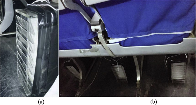
Fig. 5 shows the prototype of the diffusers used and their locations in the cabin mockup. Each diffuser had a damper for airflow balancing. The diffuser grille was made of Plexiglas because it can easily control the airflow direction, and the nine blinds in each diffuser grille directed the flow toward the breathing zone of the passenger. A fiber filter was inserted between the grille and the damper to create a stable and uniform flow. In future application, the seat legs should be adjusted so that they do not block the leg area. The air supply system was insulated.
Fig. 5.
(a) A close-up view of a diffuser and (b) the diffusers installed under the seats.
Table 1 lists the airflow rates measured by the constant tracer-gas method for each diffuser, with an average of 7.63 L/s per diffuser. The relative error for all the diffusers with the average airflow rate was 6.5% on average and 19% maximum. It was difficult to balance the flow perfectly.
Table 1.
Airflow rates from the diffusers (L/s).
| Seat number | F | E | D | C | B | A |
|---|---|---|---|---|---|---|
| 1 | 6.58 | 6.31 | 6.18 | 7.19 | 7.05 | 6.65 |
| 2 | 8.26 | 8.19 | 7.99 | 7.45 | 7.72 | 8.13 |
| 3 | 8.13 | 7.99 | 7.39 | 7.99 | 8.13 | 8.26 |
| 4 | 7.05 | 6.18 | 6.92 | 7.86 | 8.19 | 7.72 |
| 5 | 7.79 | 7.86 | 7.59 | 8.19 | 8.26 | 9.13 |
| 6 | 7.32 | 7.52 | 7.19 | 8.19 | 8.13 | 7.86 |
| 7 | 8.06 | 7.72 | 7.39 | 7.59 | 7.66 | 7.59 |
Fig. 6 is an example of the surface temperature distribution on the manikins as measured by an infrared camera. The image shows that the temperature was not uniform. Therefore, this investigation used the average temperature of each section. The average temperatures of the heads, chests, abdomens, thighs, and calves of all 38 manikins were 31.0, 32.3, 36.0, 34.2, and 25.4 °C, respectively.
Fig. 6.
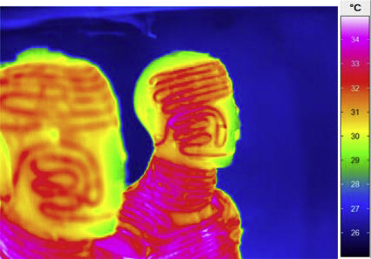
Example of manikin surface temperature distribution measured by an infrared camera.
3.3.1. Air velocity distribution
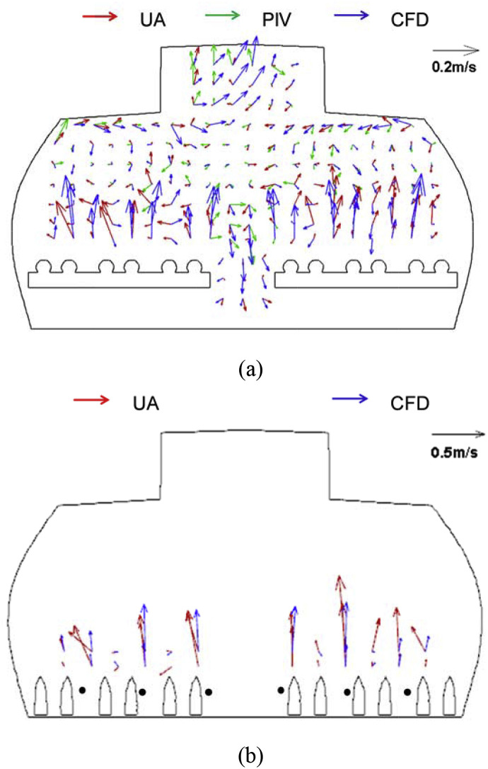
Fig. 7 (a) compares the air distributions in CS4 as measured by UAs, PIV, and CFD. The UA results show that the air traveled upward in the lower part of the cross section, where PIV could not measure anything because of the difficulty in shining the laser light into this region. The upward flow was maintained in this region because the air was directed obliquely upward from the supply diffusers and because of the thermal plumes generated by the manikins. Moreover, both the PIV and UA results indicate that the flow direction in the aisle was downward. The reason for the downward flow could be that the proposed ventilation system created two circulations, one on each side of the cabin.
Fig. 7.
Measured and simulated air velocity distribution in (a) CS4 and (b) the leg area that was located 0.15 m in front of CS4.
The velocity magnitude was small (generally less than 0.2 m/s) in the occupied zone in CS4. However, discrepancies were observed for the results measured by the PIV system and UAs. For instance, at the breathing level of passenger 4D, the air traveled downward according to PIV, but upward according to the UAs. The reason for this difference may be that the UA system measured average velocity over a span of 3 cm in each direction, as determined by the dimensions of the UA sensor, whereas the PIV system captured the data at a specific point. Since the airflow in the cabin was extremely complex, such a difference between UA and PIV might result in the discrepancy of the measured data. The numerical results predicted the general pattern of the air velocity distribution, such as the movement of air upward in the lower region and downward in the aisle, which was consistent with the experimental data.
In the leg area shown in Fig. 7(b), the measured air velocity was lower than 0.5 m/s. It is obvious that the air traveled upward immediately after leaving the diffusers. The UA sensor was too bulky to measure the area between the legs, and thus the air velocity close to the feet was measured by a hot-wire anemometer. The black dots in Fig. 7(b) represent the sampling locations for the anemometer. The velocity magnitude at these locations was found to be in the range of 0.10–0.27 m/s. Therefore, the air velocity magnitude in the leg area was acceptable. Compared with the experimental data, the CFD simulations were able to capture the general trend of the air distribution and provide results with acceptable accuracy.
3.3.2. Air temperature distribution
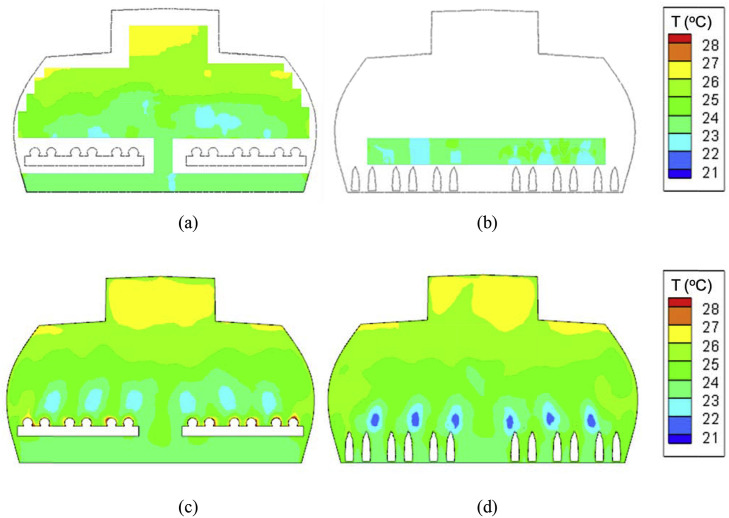
Fig. 8 (a) and (b) show the measured temperature distribution in CS4 and in the section that crossed the leg area. Temperature stratification can be seen in CS4, and the average temperature difference between the heads and ankles was 2.5 K, with the highest difference value as shown in Fig. 8(a). Therefore, the proposed ventilation system would provide an acceptable thermal environment in an airliner cabin. However, the temperature distribution in the occupied zone would not be as uniform as that generated by a mixing ventilation system. Furthermore, the temperature profile in CS4 was not symmetric, possibly because of slight differences in thermo-fluid and geometric conditions. In fact, the asymmetric distribution was stable. As shown in Fig. 8(b), the temperature in the area corresponding to the diffusers was lower than that in the surrounding environment. Therefore, if a passenger placed his/her legs directly in front of a diffuser, he/she might feel cold.
Fig. 8.
Measured air temperature distributions in (a) CS4 and (b) the leg area, and simulated air temperature distributions in (c) CS4 and (d) the section across the leg area.
The temperature distribution predicted by CFD is shown in Fig. 8(c) and (d). For CS4, the CFD simulation was able to predict the temperature stratification reasonably well in comparison with the experimental results. As shown in Fig. 8(d), the predicted temperature was lower than the measured temperature in the area close to the diffusers. The thermocouples sampled the temperature at an interval of 10 cm, and they may have missed the lowest temperature in that area during the experiment.
3.3.3. Contaminant concentration distribution
Fig. 9 shows the measured contaminant concentration distribution in CS4 when the source was at 4D. The results indicate that the contaminant stayed mainly in the upper left region of the cabin after being exhaled by the passenger. It would also be dispersed to the passengers seated in 4E and 4F. In this experiment, the only exhaust was located in the center of the ceiling. If exhausts were also present on the upper side walls, they might help in reducing the contaminant concentration for the passengers in seats 4E and 4F.
Fig. 9.
SF6 concentration distribution in CS4 normalized by the concentration in the exhaust air when the SF6 source is at 4D: (a) experimental measurement and (b) CFD simulation.
Discrepancies existed between the measured and simulated SF6 concentrations. The CFD results predicted that the SF6 would travel downward toward the aisle, but this movement was not observed in the experiment. The travel pattern of the SF6 was sensitive to the air distribution around the source location. According to Fig. 7(a), the experiment depicted flow movement toward the left at the source location (4D), whereas CFD predicted a downward flow.
Many previous studies have demonstrated that it is difficult to precisely predict the airflow, temperature, and contaminant concentration distribution in real or full-scale-mockup aircraft cabins [11,[22], [23], [24]]. Specifically, it is very challenging to precisely measure the boundary conditions due to the complex geometry and limited space in the cabin. However, the CFD simulations were able to capture the general trend of the air, temperature, and contaminant concentration distribution. The capability of predicting the general trends of the distribution would be very useful in the stage of the preliminary design.
4. System optimization
According to the experimental data, the contaminant concentration distribution in the cabin was not ultimately satisfactory. For instance, the contaminant concentration was still quite high in the breathing zone of the passengers in seats 4E and 4F. Improvements to the system parameters, such as adding more exhaust slots, could facilitate faster escape of the contaminant. Therefore, we used the validated CFD program to further design the environment inside a fully occupied one-row section of the economy cabin of a widely-used airplane, the Boeing 737. The goal here was to reduce contaminant transport and maintain cabin thermal comfort.
4.1. Design objectives
Dimensionless exposure, an index widely used in assessing personal exposure [[25], [26], [27]], is defined as:
| (3) |
where Cbreathingzone is the contaminant concentration in a passenger's breathing zone, and C* the contaminant concentration in the return air. C* can be calculated by:
| (4) |
where S is the contaminant emission rate, and Q the air supply rate of the ventilation system.
The new ventilation system aims to facilitate faster escape of the contaminant through the exhaust. The efficiency of contaminant removal was determined as:
| (5) |
where ηremoval is the contaminant removal efficiency, Ci,exh (kg/m3) the contaminant concentration at the exhaust face i, Qi,exh (m3/s) the airflow rate discharged by the exhaust face i, and S (kg/m3) the contaminant emission rate. The contaminant removal efficiency indicates the percentage of exhaled contaminant that is prevented from traveling to the front or back rows. The higher the efficiency, the lower the contaminant concentration level will be in the front and back rows. Therefore, this investigation aimed to minimize the dimensionless exposure for passengers, and maximize the contaminant removal efficiency. Note that this parameter might not be able to fully characterize the longitudinal contaminant transport. More efforts will be made to systematically investigate the contaminant transport between rows in an aircraft cabin with the proposed ventilation system.
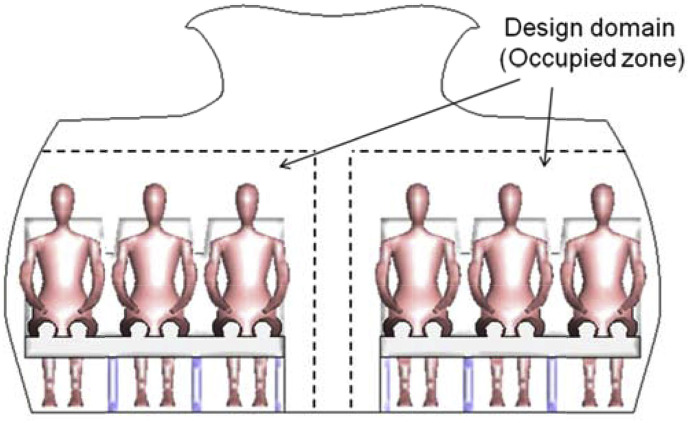
The proposed system must also satisfy the thermal comfort requirements for cabin environments. A modified predicted mean vote for air cabins (PMVc) was used by Cui et al. [28] to evaluate the thermal comfort level. This study considered both summer and winter conditions, with the clothing levels for summer and winter assumed to be 0.57 clo and 1.01 clo [29], respectively. The diffusers were so close to passengers that they may have created a draft. Therefore, this study used the “percent dissatisfied” (PD) developed by Fanger et al. [30] to predict the risk of draft. ASHRAE [31] recommends a PMV level of −0.5 to 0.5, and a PD within 15%. This study used the ASHRAE standards for PMV and PD as the design criteria for thermal comfort. The design domain was the occupied zone [32] shown in Fig. 10 .
Fig. 10.
Schematic of the design domain for the airliner cabin with the proposed ventilation system.
4.2. System optimization
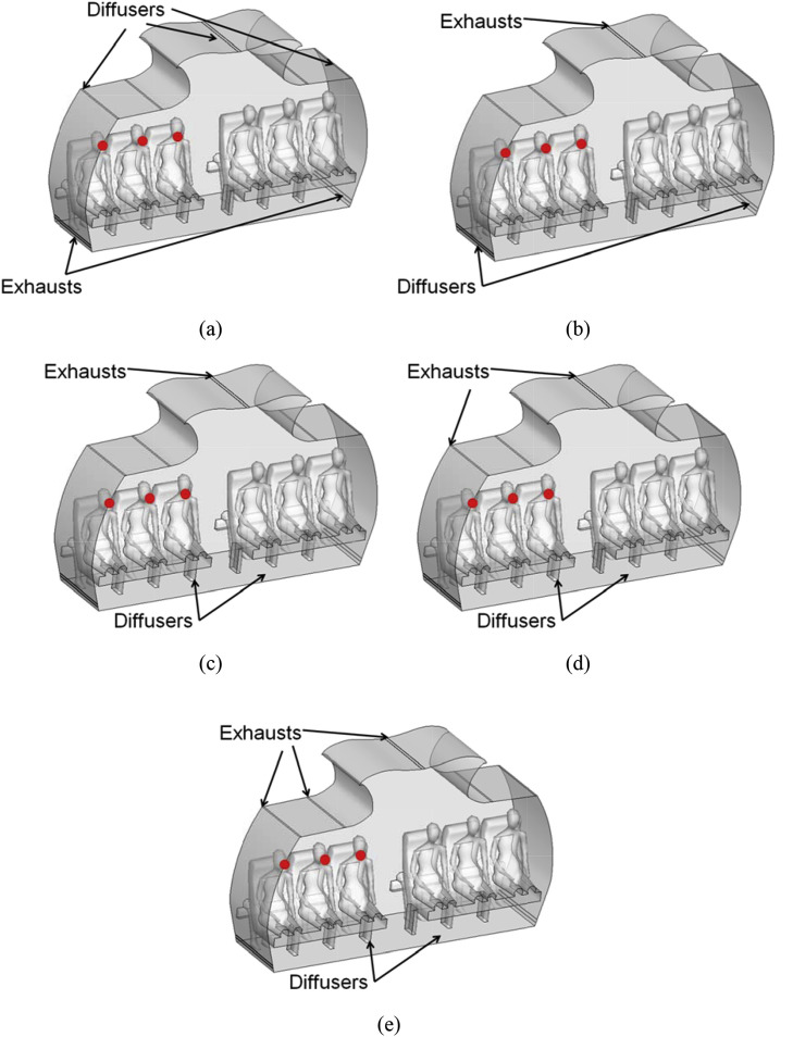
Various parameters can influence the contaminant removal efficiency and cabin thermal comfort. This study evaluated a number of cases with different parameters in order to identify the best design. Fig. 11 is a schematic of a one-row section of the fully occupied economy-class cabin of a Boeing 737 airplane with (a) mixing ventilation system, (b) displacement ventilation system, and (c), (d) and (e) the proposed system. The first two systems were chosen for the purpose of comparison, for evaluation of the proposed system's ability to reduce contaminant transport. The mixing ventilation system had two linear air-supply diffusers in the center of the ceiling and one on the upper side of each wall. The exhausts were in the side walls near the floor. The displacement ventilation system supplied air through two linear diffusers on the side walls near the floor and extracted air through the ceiling center. The proposed system had three possible exhaust configurations. Fig. 11(c) shows two exhaust slots located in the center of the ceiling, Fig. 11(d) has two additional exhaust slots on the upper side walls, and Fig. 11(e) another two slots under the luggage bins. The width of the exhaust was 2 mm. For all the systems, the total air supply rate was 0.047 m3/s for this one-row section. The supply-air temperature was 19.3 °C. The surface temperatures of the walls and the passengers were set at 24.5 and 31 °C, respectively. The source locations were assumed to be at the mouths of passengers seated in the window, middle, and aisle seats on the left size of the cabin.
Fig. 11.
Schematic of the one-row section of a fully occupied economy cabin with (a) mixing ventilation, (b) displacement ventilation, (c) proposed ventilation with two exhaust slots in the ceiling center, (d) proposed ventilation with four exhaust slots, and (e) proposed ventilation with six exhaust slots.
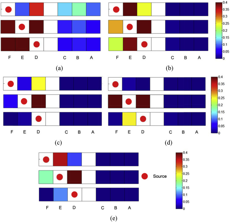
Fig. 12 summarizes the distribution of dimensionless exposure he one-row section of a fully occupied economy cabin with different ventilation systems. The mixing ventilation system was less efficient in controlling the contaminant transport compared with other ventilation system, since the contaminant was more likely to transport to the other half of the cabin. For aisle and window seat sources, the proposed system provided dimensionless exposure less than 0.25. However, the exposure for passenger in seat E for window seat source was 1.52 with displacement ventilation, and that in seat E was for aisle seat source was 0.38. For middle seat, the exposure in seat D was higher than 0.4 for all ventilation systems.
Fig. 12.
Distribution of dimensionless exposure of the one-row section of a fully occupied economy cabin with (a) mixing ventilation, (b) displacement ventilation, (c) proposed ventilation with two exhaust slots in the ceiling center, (d) proposed ventilation with four exhaust slots, and (e) proposed ventilation with six exhaust slots.
To quantitatively assess the proposed ventilation system, Table 2 compares the average computed dimensionless exposure among the recipients in the three seats. For each source location, an average result across the row was reported. The proposed system provided lower dimensionless exposure than the other two systems for the window seat and aisle seat source locations. For the middle seat source, however, the proposed system provided lower exposure than the mixing ventilation system, but higher exposure than the displacement ventilation system. In addition, the exposure decreased from 0.323 to 0.182 with the increase in the number of exhaust slots in the proposed system. This is because adding slots reduced air stagnation and facilitated the escape of the contaminant directly through the exhaust. The proposed system configurations with two, four, and six exhaust slots provided comparable average dimensionless exposure values: 0.128, 0.113, and 0.098, respectively. The four-exhaust system decreased the average exposure in the cabin by 57% and 53%, respectively, compared with the mixing and displacement ventilation systems.
Table 2.
Comparison of the average dimensionless exposure among the recipients for the proposed system, mixing system, and displacement system.
| Exhaust number |
Source location |
Average |
Maximum |
|||
|---|---|---|---|---|---|---|
| Window seat |
Middle seat |
Aisle seat |
||||
| Proposed system | 2 |
0.059 |
0.323 |
0.003 |
0.128 |
0.323 |
| 4 |
0.004 |
0.280 |
0.055 |
0.113 |
0.280 |
|
| 6 | 0.089 | 0.182 | 0.022 | 0.098 | 0.182 | |
| Mixing ventilation | 0.165 | 0.396 | 0.235 | 0.265 | 0.396 | |
| Displacement ventilation | 0.353 | 0.250 | 0.124 | 0.242 | 0.353 | |
Table 3 summarizes the computed contaminant removal efficiency for the various systems. For window and middle source locations, the proposed system with four and six exhaust slots provided higher contaminant removal efficiency than the mixing and displacement ventilation systems. The proposed system with two exhausts also provided higher removal efficiency than the other two systems for the middle seat location. For the aisle seat source, however, the proposed system with all exhaust configurations provided higher efficiency than the mixing ventilation system but lower results with the displacement ventilation system. In addition, for the window seat source, the proposed system with two exhaust slots had the described performance. This is because the sources were in the stagnation zone. The proposed system with four exhaust slots had slightly better removal efficiency than that of the system with six-exhausts, while the four-exhaust system had slightly higher dimensionless exposure than the six-exhaust system. Note that the configuration of the four-exhaust system is simpler. Therefore, it is overall the best choice. The four-exhaust system increased the contaminant removal in the cabin by 2.6 times and 0.4 times, respectively, compared with the mixing and displacement ventilation systems.
Table 3.
Comparison of contaminant removal efficiency for the proposed system, mixing system, and displacement system.
| Exhaust number |
Source location |
Average |
Minimum |
|||
|---|---|---|---|---|---|---|
| Window seat |
Middle seat |
Aisle seat |
||||
| Proposed system | 2 |
29.2% |
30.5% |
34.5% |
31.4% |
29.2% |
| 4 |
78.2% |
50.4% |
18.6% |
49.1% |
18.6% |
|
| 6 | 67.6% | 53.0% | 21.2% | 47.3% | 21.2% | |
| Mixing ventilation | 14.5% | 15.7% | 10.8% | 13.7% | 10.8% | |
| Displacement ventilation | 39.1% | 21.7% | 43.5% | 34.8% | 21.7% | |
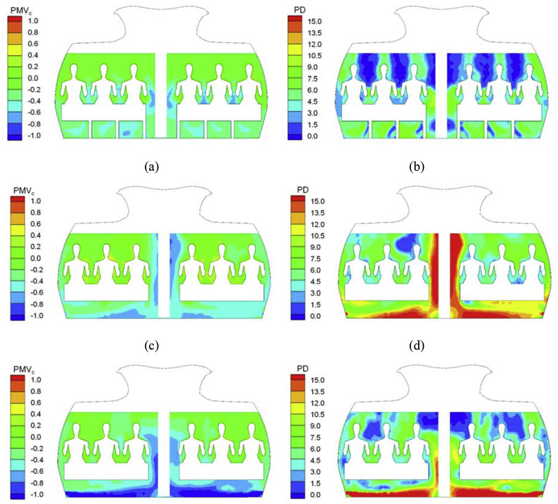
Fig. 13 (a) depicts the PMVc distribution in the cabin, generated by the proposed system with four exhaust slots in summer. The proposed system turned out to have similar PMVc values under summer and winter conditions with different numbers of exhaust slots. Therefore, the results for the proposed system with two slots and six slots are not presented here. The average PMVc values in the cabin under summer and winter conditions were 0.31 and 0.11, respectively. ASHRAE [28] recommends a PMV range of −0.5 to 0.5, and the PMVc clearly satisfied the ASHRAE standard in this cabin. To further assess the proposed system, Fig. 13(c) and (d) show the PMVc distribution under the summer conditions with the mixing and displacement ventilation systems. The average PMVc value under the summer conditions with the proposed system (−0.31) was lower than that with the mixing ventilation system (−0.26), and higher than that with the displacement ventilation system (−0.41). The trend also held for the winter conditions. Thus, the proposed system has the potential to reduce energy consumption by the HVAC system when compared with the mixing ventilation system, but not in comparison with the displacement ventilation system.
Fig. 13.
Distributions of (a) PMVc under summer conditions and (b) PD in the cabin with the proposed system with four exhausts; (c) PMVc under summer conditions and (d) PD in the cabin with the mixing ventilation system; and (e) PMVc under summer conditions and (f) PD in the cabin with the displacement ventilation system.
Fig. 13(b) depicts the PD distribution in the cabin with the proposed system with four exhaust slots. ASHRAE [28] recommends that the PD level be within 15%, and the PD level clearly satisfied the ASHRAE standard in this section of the cabin. Although the system created a draft risk in the area near the diffuser outlets, it was only a small region within the occupied zone (1.88%). Meanwhile, Fig. 13(d) and (f) show the PD distributions for the mixing and displacement ventilation systems. The “dissatisfied” zone of the design domain with the mixing and displacement ventilation systems were 9.97% and 6.64%, respectively, which were larger than that with the proposed system. This is because the two systems would generate a large vortex on each side of the cabin, resulting in a high PD level in the aisle and near the floor in the occupied zone. Thus, the proposed system was able to reduce the draft risk in the occupied zone in comparison with the other two systems.
5. Conclusions
This investigation proposed a new ventilation system to reduce contaminant transport and maintain thermal comfort in airliner cabins. The following are the major conclusions drawn from the study:
-
•
The proposed ventilation system was manufactured and then installed in a fully occupied seven-row, single-aisle airliner cabin mockup. The air velocity, air temperature, and contaminant distributions in the mockup were measured. It demonstrated good contaminant removal potential and acceptable thermal comfort. Despite the fact that the diffusers in the proposed system were close to the passengers' legs, the air velocity magnitude was small in the leg area and therefore would not create a draft. However, if a passenger placed his/her legs directly in front of the diffuser, he/she might feel cold.
-
•
This study also conducted CFD simulation of the air distributions in the mockup, and the experimental data was used to validate the CFD results. The accuracy of the CFD simulation was acceptable for designing the cabin airflow.
-
•
The study found the exhaust location to be a crucial design parameter for contaminant removal in airliner cabins with the proposed system. The validated CFD program was used to evaluate the location and number of exhausts in a one-row section of a fully occupied Boeing 737 cabin. The system configuration with four exhausts seemed to be the best choice, as it decreased the average exposure in the cabin by 57% and 53%, respectively, when compared with the mixing and displacement ventilation systems. The four-exhaust system also increased contaminant removal in the cabin by 2.6 times and 0.4 times, respectively, when compared with mixing and displacement ventilation systems. The PMVc with the proposed system was lower than that with the mixing ventilation system, but higher than that with the displacement ventilation system.
Acknowledgements
The authors would like to thank Congcong Wang, Jiayu Li, Xilei Dai, Wuxuan Pan, Lizhi Jia, and Wenhua Chen of Tianjin University for their advice and help in conducting the experiment. The research presented in this paper was partially supported by the national key R&D project of the Ministry of Science and Technology, China, on “Green Buildings and Building Industrialization” through Grant No. 2016YFC0700500 and by the Chinese Natural Science Foundation through Grant No. 51478302.
References
- 1.Moser M.R., Bender T.R., Margolis H.S., Noble G.R., Kendal A.P., Ritter D.G. An outbreak of influenza aboard a commercial airliner. Am. J. Epidemiol. 1979;110(1):1–6. doi: 10.1093/oxfordjournals.aje.a112781. [DOI] [PubMed] [Google Scholar]
- 2.Kenyon T.A., Valway S.E., Ihle W.W., Onorato I.M., Castro K.G. Transmission of multidrug-resistant Mycobacterium tuberculosis during a long airplane flight. N. Engl. J. Med. 1996;334(15):933–938. doi: 10.1056/NEJM199604113341501. [DOI] [PubMed] [Google Scholar]
- 3.Olsen S.J., Chang H.L., Cheung T.Y.Y., Tang A.F.Y., Fisk T.L., Ooi S.P.L., Kuo H.W., Jiang D.D.S., Chen K.T., Lando J., Hsu K.H. Transmission of the severe acute respiratory syndrome on aircraft. N. Engl. J. Med. 2003;349(25):2416–2422. doi: 10.1056/NEJMoa031349. [DOI] [PubMed] [Google Scholar]
- 4.ACI (Airports Council International) 2007. The Global Airport Community.www.airports.org/aci/aci/file/AnnualReport/ACIAnnualReport2006FINAL.pdf [Google Scholar]
- 5.Li Y., Leung G.M., Tang J.W., Yang X., Chao C.Y.H., Lin J.Z., Lu J.W., Nielsen P.V., Niu J., Qian H., Sleigh A.C. Role of ventilation in airborne transmission of infectious agents in the built environment–A multidisciplinary systematic review. Indoor Air. 2007;17(1):2–18. doi: 10.1111/j.1600-0668.2006.00445.x. [DOI] [PubMed] [Google Scholar]
- 6.Liu W., Wen J., Chao J., Yin W., Shen C., Lai D., Lin C.-H., Liu J., Sun H., Chen Q. Accurate and high-resolution boundary conditions and flow fields in the first- class cabin of an MD-82 commercial airliner. Atmos. Environ. 2012;56:33–44. [Google Scholar]
- 7.Cao X., Liu J., Chen Q. Particle image velocimetry measurement of indoor airflow field: a review of the technologies and applications. Energy Build. 2014;69:367–380. [Google Scholar]
- 8.Li B., Duan R., Li J., Huang Y., Yin H., Lin C.H., Wei D., Shen X., Liu J., Chen Q. Experimental studies of thermal environment and contaminant transport in a commercial aircraft cabin with gaspers on. Indoor Air. 2016;26:806–819. doi: 10.1111/ina.12265. [DOI] [PubMed] [Google Scholar]
- 9.Zhang T., Chen Q. Novel air distribution systems for commercial aircraft cabins. Build. Environ. 2007;42(4):1675–1684. doi: 10.1016/j.buildenv.2009.09.010. [DOI] [PMC free article] [PubMed] [Google Scholar]
- 10.You R., Liu W., Chen J., Lin C.-H., Wei D., Chen Q. Predicting airflow distribution and contaminant transport in aircraft cabins with a simplified gasper model. J. Build. Perform. Simulation. 2016;9(6):699–708. [Google Scholar]
- 11.You R., Chen J., Lin C.-H., Wei D., Chen Q. Investigating the impact of gaspers on cabin air quality in commercial airliners with a hybrid turbulence model. Build. Environ. 2017;111:110–122. doi: 10.1016/j.buildenv.2016.10.018. [DOI] [PMC free article] [PubMed] [Google Scholar]
- 12.Lee K.S., Zhang T., Jiang Z., Chen Q. Comparison of airflow and contaminant distributions in rooms with traditional displacement ventilation and under-floor air distribution systems. Build. Eng. 2009;115(2) [Google Scholar]
- 13.Schmidt M., Müller D., Gores I., Markwart M. 11th International Conference on Indoor Air Quality and Climate, Copenhagen, Denmark. 17. -22. Aug. 2008. Numerical study of different air distribution systems for aircraft cabins. [Google Scholar]
- 14.Müller D., Schmidt M., Müller D. Proceedings of the 3rd International Workshop on Aviation System Technology, Hamburg, Germany. 31 Mar.-01. Apr. 2011. Application of a displacement ventilation system for air distribution in aircraft cabins. [Google Scholar]
- 15.Bosbach J., Heider A., Dehne T., Markwart M., Gores I., Bendfeldt P. 28th International Congress of the Aeronautical Sciences ICAS2012, Brisbane, Australia, 23. - 28. Sept. 2012. Evaluation of cabin displacement ventilation under flight conditions. [Google Scholar]
- 16.You R., Chen J., Shi Z., Liu W., Lin C.H., Wei D., Chen Q. Experimental and numerical study of airflow distribution in an aircraft cabin mock-up with a gasper on. Journal of Building Performance Simulation. 2016;9(5):555–566. [Google Scholar]
- 17.Chen Q. Comparison of different k-ε models for indoor air flow computations. Numer. Heat Tran., Part B—Fundamentals. 1995;28(3):353–369. [Google Scholar]
- 18.Zhang Z., Zhang W., Zhai Z.J., Chen Q.Y. Evaluation of various turbulence models in predicting airflow and turbulence in enclosed environments by CFD: Part 2—comparison with experimental data from literature. HVAC R Res. 2007;13(6):871–886. [Google Scholar]
- 19.Wang M., Chen Q. Assessment of various turbulence models for transitional flows in an enclosed environment (RP-1271) HVAC R Res. 2009;15(6):1099–1119. [Google Scholar]
- 20.Zhang Z., Chen Q. Comparison of the Eulerian and Lagrangian methods for predicting particle transport in enclosed spaces. Atmos. Environ. 2007;41(25):5236–5248. [Google Scholar]
- 21.ANSYS . Fluent Inc.; Lebanon, NH: 2010. Fluent 12.1 Documentation. [Google Scholar]
- 22.Zhang Z., Chen X., Mazumdar S., Zhang T., Chen Q. Experimental and numerical investigation of airflow and contaminant transport in an airliner cabin mockup. Build. Environ. 2009;44(1):85–94. [Google Scholar]
- 23.Liu W., Wen J., Lin C.-H., Liu J., Long Z., Chen Q. Evaluation of various categories of turbulence models for predicting air distribution in an airliner cabin. Build. Environ. 2013;65:118–131. [Google Scholar]
- 24.Yan Y., Li X., Shang Y., Tu J. Evaluation of airborne disease infection risks in an airliner cabin using the Lagrangian-based Wells-Riley approach. Build. Environ. 2017;121:79–92. doi: 10.1016/j.buildenv.2017.05.013. [DOI] [PMC free article] [PubMed] [Google Scholar]
- 25.Olmedo I., Nielson P.V., Ruiz de Adana M., Jensen R.L., Grzelecki P. Distribution of exhaled contaminants and personal exposure in a room using three different air distribution strategies. Indoor Air. 2011;22:64–76. doi: 10.1111/j.1600-0668.2011.00736.x. [DOI] [PubMed] [Google Scholar]
- 26.Liu L., Li Y., Nielson P.V., Wei J., Jensen R.L. Short-range airborne transmission of expiratory droplets between two people. Indoor Air. 2017;27:452–462. doi: 10.1111/ina.12314. [DOI] [PubMed] [Google Scholar]
- 27.Bjørn E., Nielson P.V. Dispersal of exhaled air and personal exposure in displacement ventilated rooms. Indoor Air. 2002;12:147–164. doi: 10.1034/j.1600-0668.2002.08126.x. [DOI] [PubMed] [Google Scholar]
- 28.Cui W., Zhu Y. Presented in the Annual Meeting of the Center for Cabin Air Reformative Environment (973 Project), Chongqing, China. 2015. Systematic study on passengers' thermal comfort under low-air-pressure environment in commercial aircraft cabin. [Google Scholar]
- 29.Handbook A.S.H.R.A.E. ASHRAE, Inc.; Atlanta, GA: 2005. Thermal Comfort Chapter, Fundamentals Volume of the ASHRAE Handbook. [Google Scholar]
- 30.Fanger P.O., Melikov H., Hanzawa H., Ring J. Air turbulence and sensation of draught. Energy Build. 1988;12:21–39. [Google Scholar]
- 31.ASHRAE . ASHRAE, Inc.; Atlanta, GA: 2007. Standard 161–2007, Air Quality within Commercial Aircraft. [Google Scholar]
- 32.Xue Y., Zhai Z., Chen Q. Inverse prediction and optimization of flow control conditions for confined spaces using a CFD-based genetic algorithm. Build. Environ. 2013;64:77–84. [Google Scholar]


