Abstract
Breathing is a high-risk behavior for spreading infectious diseases in enclosed environments, so it is important to investigate the characteristics of human exhalation flow and dispersal of exhaled air to reduce the risk. This paper used two-dimensional time-resolved particle image velocimetry (2D TR-PIV) to measure the exhaled flow from a breathing thermal manikin. Since the exhaled flow is transient and periodic, the phase-averaged method was used to analyze the flow characteristics. The results showed that the velocity profile of the flow exiting the mouth was bell-shaped for exhalation and flat for inhalation. The exhaled flow showed different characteristics during each stage of the exhalation process. In the initial phase, a mushroom-shaped flow arose, while some jet characteristics appeared in the middle phase. The effect of thermal buoyancy and thermal plume on the exhaled flow was analyzed. Clear turbulence characteristics were found in the exhaled flow, and the turbulence fluctuation was very strong in the transition stage between exhalation and inhalation. The last finding was that the distribution and value of vorticity were different in each phase. The results of quantitative PIV provided detailed information about the boundary condition set and validation data for CFD simulation.
Keywords: Exhaled flow, PIV, Boundary condition, Phase-averaged method, Turbulence characteristics
Highlights
-
•
The exhaled flow from a breathing thermal manikin is measured by 2D TR-PIV.
-
•
The phase-averaged method is used to analyze the flow characteristics.
-
•
The exhaled flow shows different characteristics at different stages during exhalation.
-
•
Clear turbulent characteristics can be found in the exhaled flow.
-
•
The turbulent fluctuations are very strong in the transition stage between exhalation and inhalation.
1. Introduction
Coughing and sneezing are considered to be high-risk behaviors for transmitting infectious diseases, and some influenza viruses have also been found in human breathing [1], [2], occurring even in a higher concentration than in sneezing and coughing [3]. Human breathing process can thereby be an important source of infectious diseases [4] that are transmitted through airborne droplets. The majority of droplets in human breathing are tiny or nuclei (smaller than 10 μm) [5], and can follow the airstream [6]. In recent years, outbreaks of airborne infectious diseases have frequently occurred, such as severe acute respiratory syndrome (SARS) in over 25 countries in 2003 [7], and the spread of the swine flu epidemic in 2009 [8], which caused high morbidity and mortality worldwide [9], [10]. The World Lung Foundation has reported that more than four million deaths are caused by acute respiratory infections (ARIS) each year. Therefore, it is extremely important to investigate the characteristics of human exhalation flow and the dispersal of exhaled air to reduce the risk of spreading infectious diseases.
The dispersal characteristics of exhaled air in enclosed spaces with different forms of ventilation have been widely studied in experiments [11], [12], [13], [14] and numerical simulations [15], [16]. When human breathing was considered as a contaminant source, different exhalation boundary conditions were used in these studies. In both early numerical studies [11], [14], [17], [18] and experiments [19], [20], [21], a constant initial exhalation velocity was used. Under other circumstances, the real sinusoidal function [7], [13], [15], [16] or a very similar time-dependent function [22], [23] was used. One study that compared steady and unsteady boundary conditions found that the distribution of contaminants was quite different and suggested that the boundary condition of a sinusoidal exhalation should not be simplified [14]. In almost all the experiments [12], [24], [25], only the velocity in the center of the exit was obtained, while the distribution of contaminants at the exit has never been illustrated. In general, the velocity profile at the exit is bell-shaped for a free jet [26]. So it could be inferred that the velocity profile for exhaled flow is also not flat at each phase either.
There are few studies that address the flow characteristics of the breathing process. The breathing process is complicated, periodic, and transient [10]. Olmedo [12] suggested that the exhaled flow can be partly modeled as a vortex ring and partly as an instantaneous turbulent jet. Most studies only showed the trajectory of the exhalation from the mouth or nose using smoke visualization, or have measured the peak values for exhalation velocity using hot sphere anemometry [11], [12], [13], [24]. Nielsen [25] showed that the peak value of instantaneous human exhalation flows can be described by an equation similar to the centerline velocity in a steady state jet. Marr investigated on turbulence intensity and anisotropy in the breathing zone, while the studies had little analysis about the turbulence characteristics of exhaled flow [27], [28]. In a word, few papers have described the turbulence characteristics of the exhaled flow. Xu [4] also pointed out that although the boundary conditions of a varying flow rate or velocity had been used in most of the computational fluid dynamics (CFD) simulations of breathing, the turbulence features have not been clearly described. Thus experimental studies of exhaled flow are required. The precise measurement of the exhaled flow and analysis of turbulent statistics could help control the exhaled contaminant transmission and facilitate the selection of the best turbulence model for CFD simulations.
In the experiment study, different breathing manikins were used to represent a real human, falling into two broad groups. The first kind of manikin had a steady breathing boundary. In some studies [20], [21], the initial breathing momentum was ignored, with a very low initial velocity. Also, a mean velocity of the exhalation process was chosen as the boundary [19]. The others had an unsteady breathing boundary. Most of the unsteady boundary used sinusoid function. However, there could be a difference in breathing pattern. In some studies [4], [12], [13], exhalation and inhalation of the manikin were carried out through different respiratory organ (mouth or nose) in a breathing process. The shapes of mouth in breathing process were also different. Some [12] were circular, and the others [4], [13] were semi-ellipsoid. However, in Marr's studies [27], [28], the manikin exhaled through nose and also inhaled through nose. And in Marr's early study [27], the breathing boundary was not sinusoid function. In a word, many different breathing manikins were used. Gupta pointed out that the exhaled flow rate of real human over time can be represent as a sinusoid function [10]. So in this study, the breathing manikin was used to breathe through mouth with a boundary of sinusoid function.
It is difficult to measure the entire jet flow using traditional point–wise velocimetry such as hot-wire or hot-sphere anemometry [29], [30]. All traditional anemometers can only measure the velocity information at the point of the probe sensor after a laborious process, making it difficult to conduct accurate and detailed measurement of multipoint turbulent airflows. Furthermore, traditional anemometry may disturb the local airflow to different degrees [31], [32]. Therefore, it could be more difficult to measure the exhaled flow using traditional velocimetry, which is more complex and unsteady comparing to free jet. However, sound measuring information can be obtained by particle image velocimetry (PIV) technique [27], [28], for instance, Marr found that the local turbulence intensity had a threefold increase in the breathing zone by PIV technique, when compared to the ambient values [27]. PIV can capture velocities and related statistical information in the global flow domain in a very short time, and the airflow is not disturbed because no intrusive sensor probe exists [32]. Therefore, PIV may be the better velocimetry for measuring the exhaled flow in the study.
In this work, experimental investigation was conducted in an environmental chamber to study the boundary conditions and turbulence characteristics of the exhaled flow from a breathing thermal manikin by TR-PIV. The objectives of present work were:
-
1.
To obtain a precise boundary of the breathing process, including the velocity profile and the turbulence intensity in boundary, which is necessary for CFD simulation.
-
2.
To analyze the flow characteristics of exhaled flow and to deepen understanding the exhaled flow. The mean velocity, vorticity and turbulence intensity obtained by experiment can provide the basic data for turbulence model and validation for CFD simulation.
2. Methods
2.1. Experimental mockup and thermal manikin
As shown in Fig. 1(a) , the experimental mockup was placed in an enclosed environmental chamber with an indoor air temperature maintained at 20 ± 1 °C using a packaged air conditioner, satisfying the recommendation of ASHRAE Standard 161-2007 [33]. The mockup was 1.2 m (length) × 1.0 m (width) × 1.5 m (height), with transparent walls, through which a laser can penetrate to form a light sheet for PIV measurements. One naked, breathing thermal manikin with a mouth (1.4 m in height when seated and a body surface area of 1.339 m2) was used to simulate an average-sized male. The breathing thermal manikin consisted of four segments, including head, trunk, left leg and right leg. The surface of the manikin was wrapped with 2 mm nickel-chromium resistance wire (32 Ω/m). The sensible heat loss of the manikin was controlled at 75 W [32] and the sensible heat loss of each segment was listed in Table 1 . In the experiment, the manikin breathed through a mouth with a 12 mm diameter circular opening [10], [13], as shown in Fig. 2 . The manikin had a respiration flow of 0.45 l per exhalation and a frequency of 15 breaths per minute, and the breathing condition was sinusoidal [10], [11], [34]. The angle of breathing flow was horizontal. The exhaled air temperature of human breath varies in different ambient air conditions, and it is about 32–36 °C when the ambient air is 20 °C [35]. Therefore, in the experiment the exhaled air temperature was set to 34 °C.
Fig. 1.
(a) Schematic of experimental platform (b) test sections schematic.
Table 1.
The sensible heat loss of each segment.
| Segment | Sensible heat loss (W) |
|---|---|
| Head | 7.4 |
| Trunk | 25.6 |
| Left leg | 21.0 |
| Right leg | 21.0 |
Fig. 2.

The detailed mouth of the breathing thermal manikin.
2.2. PIV measurement system
Two-dimensional time-resolved particle image velocimetry (2D TR-PIV) was used in the experiment, as shown in Fig. 1(b). The PIV system consisted of a Dantec NanoSense MKⅢcamera with a resolution of 1280 × 1024 pixels and a Pegasus double-cavity Nd:YLF laser with a pulse energy of 10 mJ at a wavelength of 532 nm. The laser beam was originally enlarged using a telescope, and then extended using a cylindrical lens to form a light sheet with an opening angle of about 30° and a thickness of 0.5 mm in front of the manikin's face. The camera was installed on a tripod and positioned perpendicularly to the light sheet. The camera and the laser were controlled to capture sequential pairs of images using a synchronizer. In the experiment, theatrical fog particles with a mean diameter of 1 μm were used as tracer particles since their density is similar to that of air. Theatrical fog is preferred for revealing detailed flow features over two other kinds of particles, oils and Di-Ethyl-Hexyl-Sebacat (DEHS), which were used in previous studies [32].
2.3. Experiment setup
Considering that the exhaled air temperature is higher than the ambient air temperature in real case, the effect of thermal buoyance on the exhaled flow will occur. Furthermore, thermal plume induced by the sensible heat loss will also affect the exhaled flow. Thus, experiments were conducted under two conditions to study the flow characteristics and the effect of thermal buoyancy and thermal plume on the exhaled flow, namely isothermal and heated conditions. Under the isothermal condition, the manikin and the exhaled air were not heated. Under the heated condition, the manikin was heated and the exhaled air was also heated to 34 °C. Under each condition, three repeated tests were conducted to obtain a precise result.
In the experimental process, a data logger for Pt1000 temperature sensors with an accuracy of ±0.3 K was used to monitor the temperature in the experimental mockup. The monitor point is shown in Fig. 3 (a). For both the isothermal and heated conditions, the temperature change is shown in Fig. 3(b), which shows that the temperature was constant during the experiment with a fluctuation less than 0.3 K.
Fig. 3.
(a) Temperature monitoring point; (b) the monitoring results under two conditions.
In the experiment, a light sheet from the laser was formed in front of the manikin's face, as shown in Fig. 1(b). For this particular system, the measurement area was 8637 mm2 (103.9 mm × 83.1 mm). The sampling frequency was 10 Hz, and 3000 image pairs were obtained for each condition. The manikin experienced 75 exhalations in the process. To reduce the background noise, the upper part of the manikin was blackened using flat lacquer [32]. The analysis of the PIV images was conducted using the Dantec software package DynamicStudio. The background noise of the raw images was first removed using background subtraction. Then, an adaptive correlation algorithm supplemented with a pinpoint accuracy sub-pixel interpolation was used to extract the velocity vectors. The size of the interrogation window was 16 × 16 pixels with a 50% overlap, which led to a spatial resolution of 0.65 mm × 0.65 mm. PIV measurements can be affected by many error sources. The errors can divided into systematic errors and statistical errors [32]. The systematic errors are mainly induced by the tracking behavior and seeding density of the particle, the background noise, the random displacement error and so on [27], [32]. The statistical error is mainly the random error. According to the method in studies [32], the uncertainty was less than 3.5% in the velocity field.
Except for the PIV measurement, the velocity over time at the exit of the manikin's mouth was obtained using IFA-300 constant-temperature anemometry. Only a mini single wire (TSI model 1260 A-T1.5) was used, which consisted of tungsten with a length of 1.5 mm and a diameter of 5 μm. The sampling frequency was set at 1000 Hz. The anemometer was calibrated before experiment and achieved a resolution of 0.01 m/s and it can provide a very good accuracy. The velocity was measured at the center of the exit of the manikin's mouth.
2.4. Phase-averaged method
Since the breathing flow is transient and periodic, the phase-averaged method should be used to analyze the result rather than the time-averaged method [27]. In this study, one breathing process was broken into 40 phases, 20 phases for exhalations and 20 phases for inhalation. The thermal manikin experienced 75 breathing process. The mean velocity for each phase was obtained by Equation (1):
Here, u φ is the mean velocity, φ represents a given phase, and N is the total number of the periods, equals to 75 in this study. u φ(n) is the instantaneous velocity of a given phase in the nth period.
3. Results
3.1. Boundary condition for breathing process
Fig. 4(a) shows the velocity profile at x/d = 0.224 for the different phases of the exhalation process. U φ.c is the centerline velocity of each phase at x/d = 0.224. The velocity profile was considered to be the same as that at the exit of the mouth for exhalation. In the region of x/d ≥ 0.224, the measured data was accurate enough to analyze the flow characteristics, whereas in the region of x/d < 0.224, the accuracy of the measured data was poor. The results show that there was a common non-dimensional velocity profile at different phases. In addition, the velocity profile was bell-shaped rather than flat at the exit of the mouth, and a velocity gradient (du/dr) existed for each phase along the radial direction. The area of the shear layer was different in the two cases, so if a constant value for each phase at the exit was set as the CFD boundary condition, inaccurate predictions for the characteristics of the exhaled flow will resulted [36].
Fig. 4.
The velocity profile at x/d = 0.224 for different phases of the breathing process. (a) Exhalation; (b) Inhalation.
Fig. 4(b) shows the velocity profile at x/d = 0.224 for different phases of inhalation process (V φ. m is the maximum velocity for inhalation). In the inhalation process, the similarity of the non-dimensional velocity was not as perfect as that of exhalation, because the inhalation process was more affected by the manikin's shape [37], [38]. Compared to the exhalation process, the non-dimensional velocity magnitude was greater than 0.68 for the range of −0.5 ≤ y/d ≤ 0.5. Thus, it can be concluded that all of the velocity at the exit for each phases can be modeled as a constant V φ. m.
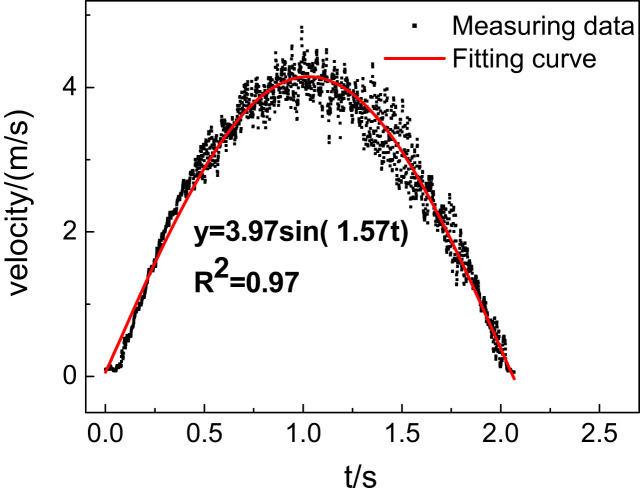
As Fig. 5 shows, the exhaled flow velocity over time was a sinusoidal function, and as Gupta pointed out, the breathing flow rate over time can be considered as a sinusoidal function [10]. The exhaled flow rate of the manikin was a sinusoidal function according to the following equations:
| (1) |
where
| (2) |
Here, Qφ is the exhaled flow rate of a given phase (l/s). As U/Uφ .c was uniform for each phase, k was a constant. As a consequence, Qφ had a positive correlation relationship with U φ .c, so the exhaled flow rate was sinusoidal. The outlet velocity profile from the manikin can be acquired using an integral expression with a known velocity profile, but mere measurement of the nearest point [24] may be inaccurate. The outlet velocity can be calculated according to these equations, which we modified from those obtained from Xu [24]:
| (3) |
| (4) |
| (5) |
| (6) |
Here, Q is the instantaneous flow rate and A is the maximum flow rate in a period. BF represents the breathing frequency. Tidal volume (TV) is the volume of one exhalation, RMV is the volume of exhalations in a minute, and k was obtained Equation (2), which may be different for other diameters.
Fig. 5.
The exit velocity in the center measured using IFA-300 constant-temperature anemometry in an exhalation process.
3.2. Mean velocity
3.2.1. Isothermal condition
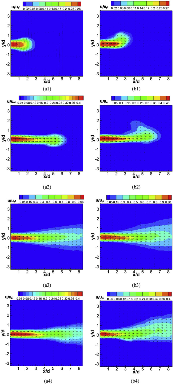
Fig. 6 shows the mean velocity contours of different phases in the exhalation process under the isothermal and heated conditions. Fig. 6(a1) and 6(a2) illustrate the mushroom flow that arose in the initial phases, which was possibly induced by the periodic flow or resistance of the ambient air. The exhaled flow had nearly no diffusion, maintaining the same width as the manikin's mouth exit. The jet characteristics could not be clearly identified.
Fig. 6.
Mean velocity contours of the exhalation process under two conditions: (a1-4) Isothermal condition; (b1-4) Heated condition; (a1/b1) φ = 2; (a2/b2) φ = 3; (a3/b3) φ = 10; (a4/b4) φ = 18.
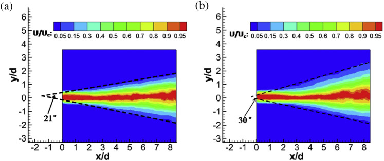
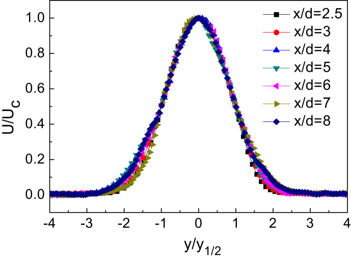
As Fig. 6(a3) shows, the exhaled flow gradually evolved similarly into a steady jet flow. Fig. 7 shows the local mean velocity U/U c contours (U c is the jet centerline velocity) of the exhaled flow in the middle phase. The liner diffusion exhibited characteristics of a free jet [39]. The tracking radial position in which the mean velocity U/U c was equal to 0.05 [39] traced a diffusion angle of about 21° under the isothermal condition. Another phenomenon was that a region just beyond the exit had a same width as that of the exit. This phenomenon was also found for the free jet [40], but the length of the region was much longer for a similar Re, which is the undisturbed region of flow. The velocity in the region of x/d ≤ 1 was greater than 0.98, which can be recognized as the exhaled flow initial region similar to the free jet. Also, the exhaled flow potential core zone can be clearly seen, that is the red (in the web version) region in Fig. 6(a3). As above mentioned, the radial velocity gradient was so great that the exhaled flow potential core zone was very small. The exhaled flow had perfect similarity of the local mean velocity profile for the axial distance x/d > 2.2, as shown in Fig. 8 . The region of x/d > 2.2 can be considered as the fully developed region. There was no similarity of the local mean velocity profile in the region of 1 < x/d < 2.2, which can be recognized as the transitional region.
Fig. 7.
Diffusion angle of the exhaled flow in the middle phase (φ = 10): (a) Isothermal condition; (b) Heated condition.
Fig. 8.
Similarity of mean velocity in the middle phase (φ = 10).
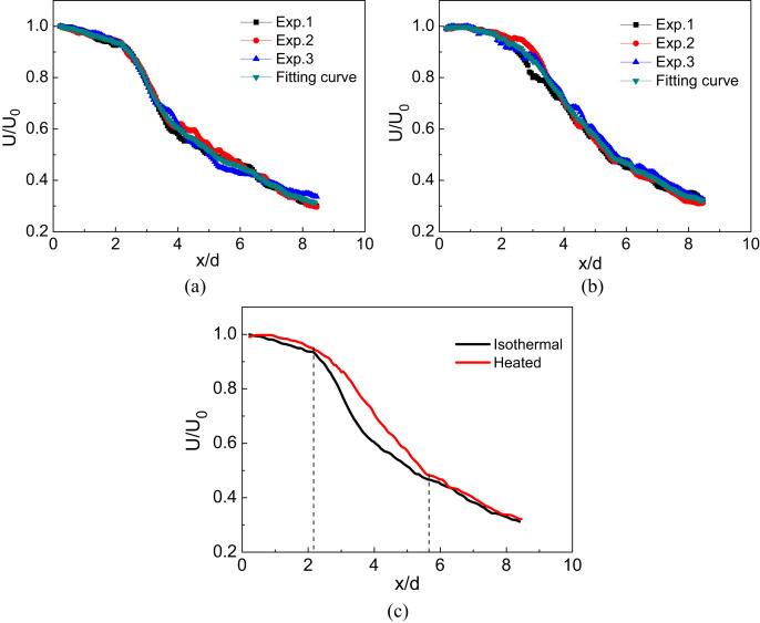
There were also some observed differences between the exhaled flow and the free jet. Fig. 9(a) shows the axial non-dimensional velocity decay curve of the exhaled flow in the middle phase. The reproducibility of the results was very good (three experiments were performed under the same condition). Unlike the free jet, the curve had four regions with distinct features. The first was in the exhaled flow initial region. The second was in the transitional region, where the decay was slow. The third region was the fully developed flow region, which had two parts, one was 2.2 < x/d < 5.6 and the other was x/d > 5.6. In the first part, 2.2 < x/d < 5.6, the decay of the exhaled flow was much greater than that in 1 < x/d < 2.2. Also, in the third part, 2.2 < x/d < 5.6, the surrounding air was obviously entrained by the exhaled flow, and a diffusion angle was formed. Gradually, the decay became constant in the fourth region, like a free jet.
Fig. 9.
Non-dimensional mean velocity distribution along the axis (a) Isothermal condition; (b) Heated condition (Experiments 1,2, and 3 are repetitive experiments); (c) Comparison of two conditions.
Nielsen [25] and Olmedo [12] found that the peak non-dimensional velocity in the centerline was inversely proportional to the dimensional distance, being similar to a free jet. The dimensional distance was x/d in this paper. Therefore, the decay of non-dimensional velocity was given by:
| (8) |
Here, U 0 is the maximum velocity, and K and n are the characteristic constant values. Unlike the expression for the free jet, the characteristic constants of K and n had different values in different regions. The constants and exponents are listed in Table 2 for the two conditions.
Table 2.
The characteristic constants for different regions for two conditions.
| Conditions | 1 < x/d < 2.2 |
2.2 < x/d < 5.6 |
x/d > 5.6 |
||||||
|---|---|---|---|---|---|---|---|---|---|
| K | n | R2 | K | n | R2 | K | n | R2 | |
| Heated | 0.998 | −0.0581 | 0.921 | 1.87 | −0.727 | 0.948 | 3.24 | −1.09 | 0.991 |
| Isothermal | 0.979 | −0.0591 | 0.980 | 1.81 | −0.785 | 0.993 | 3.20 | −1.08 | 0.991 |
For the end phase shown in Fig. 6(a4), the jet characteristic disappeared gradually. The diffusion angle decreased, and the length of the region that had the same width as the exit increased. As the exhaled flow momentum decreased, the velocity contour became asymmetric, and then the exhalation process ended.
3.2.2. Comparison of two conditions
Comparing the same phases in Fig. 6(b1-2), the initial segment of the exhaled flow, having a great momentum, was almost not affected by the thermal plume and thermal buoyancy, but these thermal effects acted upon the later segment of the exhaled flow because its momentum was very small. In other words, the mushroom-shaped flow became asymmetric with a tendency to move upward due to the thermal plume and thermal buoyancy. Therefore, it can be predicted that there will be a zone with a high contaminant concentration close to the manikin's head under the heated condition [16]. However, this phenomenon cannot be predicted with a steady boundary condition in the exhalation process.
In the middle phase, the diffusion angle (about 30°) for the heated condition was greater than that of the isothermal condition, as shown in Fig. 7(b). The axial non-dimensional velocity decay curves for both the isothermal and heated conditions are shown in Fig. 9(a) and (b). The decay of the heated condition was slower in 2.2 < x/d < 5.6, which is shown in Fig. 9(c) and also in Xu's work [24], although Xu did not provide an explanation. Our explanation was that the temperature difference (about 9 K between the exhaled air and the surrounding air) promoted entrainment in the boundary of the exhaled flow, and in turn reduced the loss of kinetic energy.
The upward thermal plume interacted with the exhaled flow, so the entrainment was also promoted [32]. In x/d > 5.6 the exhaled air temperature decreased to reach the same temperature as the ambient air [4], and the thermal plume became weak, so the decay curve was similar for the two conditions. Thus, we concluded that a high exhaled air temperature and corresponding thermal plume helped to spread the exhaled flow profile more widely and to promote the diffusion of the contaminant, which we should be concerned about.
For the end phase, the exhaled flow clearly ascended, as shown in Fig. 6(b4), and became more asymmetric under the heated condition. Similarly, the region of the exhaled flow was greater, promoting contaminant diffusion.
3.3. Vorticity
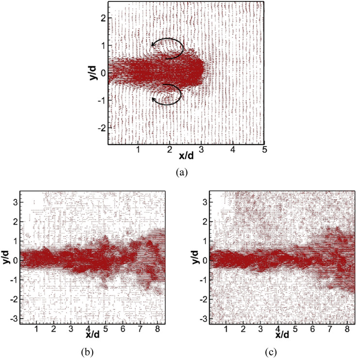
Fig. 10 shows the instantaneous velocity vector fields of different phases in the exhalation process. For the initial phase (φ = 2), there was a pair of large-scale vortices appearing on the two sides of the mushroom-shaped flow, and the exhaled flow was relatively stable. In the middle phase, many vortices appeared in the free shear region, which demonstrated a clear turbulent structure. In the final phase (φ = 18), the vortex structure can also be clearly seen. It can be concluded that a pair of vortices form at the beginning of the exhalation process, and they quickly evolved, existing throughout the entire exhalation process. Because the spatial vortex plays an important role in the evolution of the exhaled flow, the phase-averaged vorticity was used to analyze this evolution. The vorticity was obtained by this equation:
| (9) |
Here, ω is the spanwise component of vorticity, u is the x-mean velocity, and v is the y-mean velocity.
Fig. 10.
The instantaneous velocity vector fields of the exhalation process under the isothermal condition: (a) φ = 2; (b) φ = 10; (c) φ = 18.
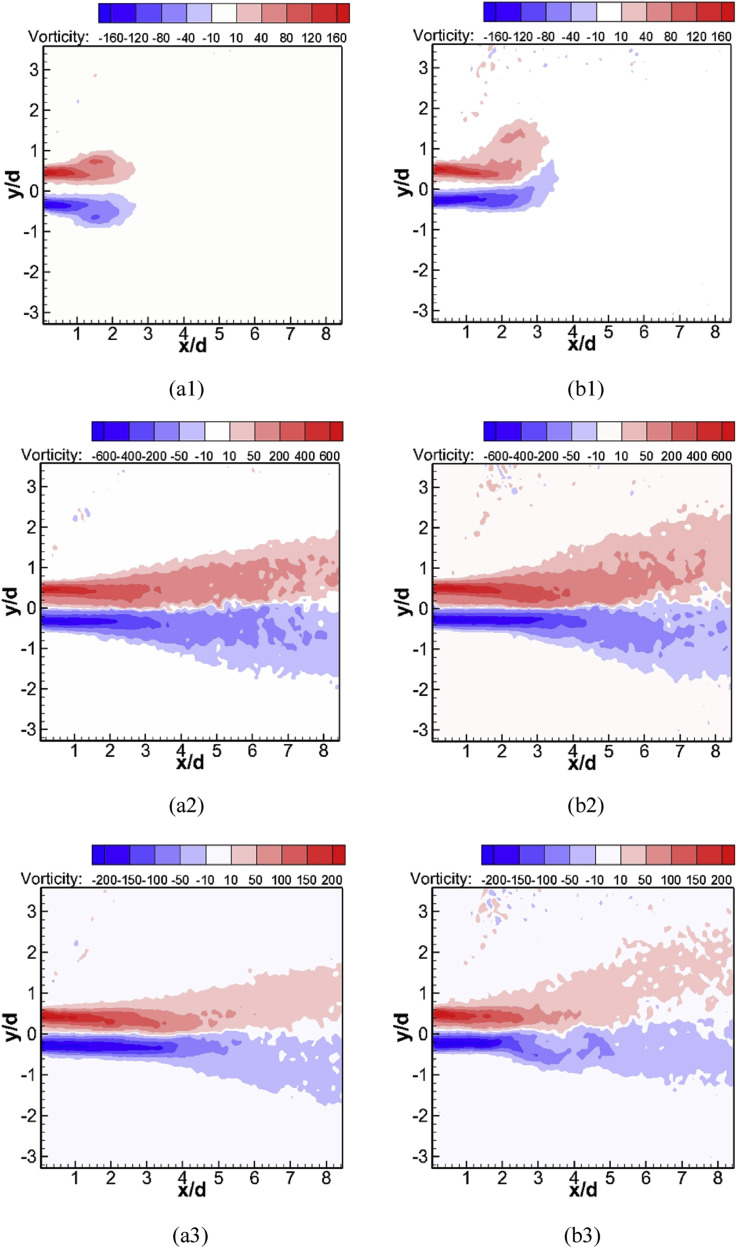
Fig. 11 shows the vorticity contours of the different phases under the two conditions. A common feature was that the positive and negative values of vorticity appeared beside the centerline for almost all cases, indicating that there was a counterclockwise rotation in the region above the centerline and a clockwise rotation in the region below the centerline. The interface between the positive and negative regions represented the centerline of the exhaled flow. The maximum absolute value appeared in the region near the exit of the manikin's mouth, where there was a large velocity gradient.
Fig. 11.
Contours of phase-averaged vorticity under two conditions: (a1-3) Isothermal condition; (b1-3) Heated condition; (a1/b1) φ = 2; (a2/b2) φ = 10; (a3/b3) φ = 18.
There were also differences between the different phases for the two conditions. At the initial phase (φ = 2), similar to the velocity field, the mushroom-shaped region appeared but was divided into two parts. It was different from the other phases in that a maximum value of vorticity arose in the center of the above-centerline and below-centerline parts. Under the heated condition, the mushroom-shaped region was also asymmetric, and the part below the centerline became small, while the other became large due to the thermal plume and thermal buoyancy.
In the middle phase, the value of vorticity was the maximum in the exhaled process and was quite large; the absolute value was above 600 in the initial section of the exhaled flow. When in x/d < 5, the decay of the vorticity value under the isothermal condition was faster than that under the heated condition. In addition, the vorticity distribution covered a larger region under the heated condition. This shows that the free shear layers covered a larger region, which promoted the diffusion of the contaminant under the heated condition. For x/d > 6, the characteristics of the two vorticity fields gradually became similar, which was the same as the observation for the velocity field.
In the final phase (φ = 18), the maximum value of vorticity decreased. With the decrease of the exhaled flow momentum, the vortex structure was easily destroyed by the thermal plume. In short, the decay of vorticity was faster under the heated condition, and the region covered by the shear layer became smaller.
3.4. Turbulence intensity
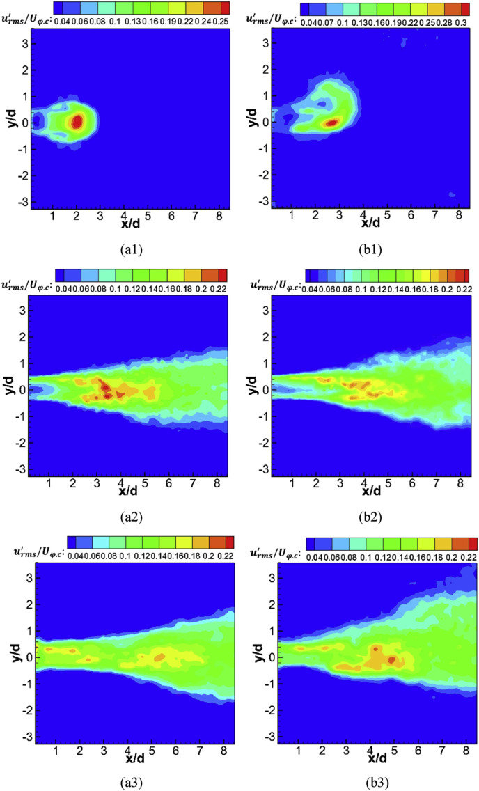
The turbulence characteristics can be seen clearly in Fig. 10, which shows that the exhaled flow was relatively stable in Fig. 10(a), whereas it appeared chaotic in Fig. 10(b/c). So, we can assume that the turbulence intensity was different in each phase. Fig. 12 shows the turbulence intensity contours of different phases under the two conditions: (U φ.c is the centerline velocity at x/d = 0.224 for each phase).
Fig. 12.
Contour of turbulence intensity urms' of exhaled flow: (a1-3) Isothermal condition; (b1-3) Heated condition; (a1/b1) φ = 2; (a2/b2) φ = 10; (a3/b3) φ = 18.
At the beginning of the exhaled flow (φ = 2), the distribution of had a similar shape as that of the velocity. The turbulence fluctuation was minimal for x/d < 1, while it rapidly became pronounced in the region x/d > 1, which may be induced by high levels of shear. A significant difference with a free jet was that the maximum turbulence intensity appeared in the centerline. Under the heated condition, the distribution of the turbulence intensity became asymmetrical. The maximum value arose in the region where the exhaled flow interacted with the thermal plume.
In the middle phase (φ = 10), as in the initial phase, the level of turbulence fluctuation was low in x/d < 1, especially in the exhaled flow potential core zone, as shown in Fig. 12(a2), while it was slightly strong under the heated condition, as shown in Fig. 12(b2). The distribution of the turbulence intensity showed symmetrical characteristics, similar to a free jet. After the exhaled flow initial region (x/d > 1), the turbulence intensity increased rapidly, increasing to its maximum at about x/d = 4, much faster than a free jet [39]. As distinct from the isothermal condition, the point at which the turbulence intensity reached its maximum occurred at after x/d = 5 under the heated condition, and the velocity decay was slower in 2.2 < x/d < 5.6. In addition, the maximum of the turbulence intensity was lower under the heated condition. For x/d > 7, the distribution became similar for the two conditions.
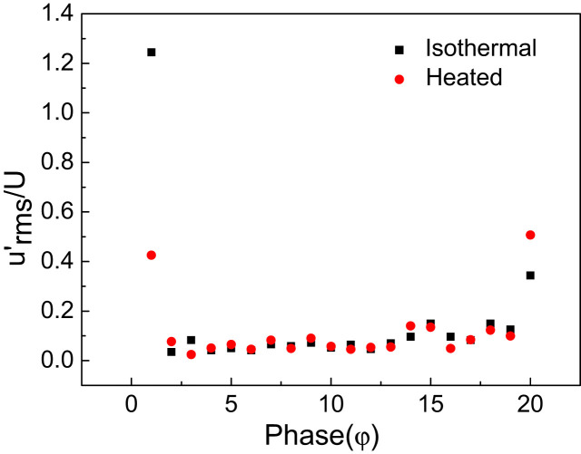
For the end phase (φ = 18), there was a large difference from previous phases since the turbulence fluctuation was also strong in x/d < 1, due to the rapid decrease of the initial momentum. The turbulence intensity at the center point of the exit is shown in Fig. 13 for the entire exhalation process. At the phase when the inhalation process had just ended and the exhalation process had just begun, the turbulence fluctuation was very strong, then decreased rapidly before slightly increasing (it is relatively stable). The turbulence fluctuation increased again in the second half of the exhalation process, becoming strong especially in φ = 18/19/20. The mean turbulence intensity was 0.055 for the first half of the exhalation, while it was 0.092 for the second half of exhalation. For x/d > 2, the turbulence intensity appeared to be asymmetrical under the heated condition since the exhaled flow interacted with the thermal plume, while the turbulence fluctuation was stronger and symmetric under the isothermal condition.
Fig. 13.
The turbulence intensity at the center point of different phases in an exhalation process.
4. Discussion
In this work, the boundary condition and turbulence characteristics of the exhaled flow from a breathing thermal manikin were measured and analyzed by TR-PIV measurement.
Compared with the traditional velocimetry, TR-PIV can obtain the velocities, vorticity and turbulence intensity in a globe domain for each phase according to time sequence, while it is rather difficult to acquire such information through traditional testing method, such as hot-wire or hot-sphere anemometry. Similar methods were also used in the studies [27], [28]. All these studies achieved good results. However, N was equal to 75 in Equation (1) of this study, while it was 500 in Marr's studies [27], [28]. Compared with the results obtained by Marr's studies, the statistical result of mean velocity was very good, while that of the vorticity and the turbulence intensity was less satisfactory. It may be induced by the value of N [32], but a greater value of N will lead to a lower sampling frequency. Some key characteristics cannot be found by a low sampling frequency especially for the periodic flow. For instance, in the transition between inhalation and exhalation the turbulence fluctuation was very strong, such phenomenon may not be found with a smaller sampling frequency. So a trade-off had to be made between the sampling frequency and the number (N) of instantaneous sample for each phase, especially when the storage of the camera is limited. And it is suggested that the number of instantaneous samples for each phase should be equal to or greater than 75. Further study is need about the trade-off.
CFD simulation would also be an important and necessary method for the verification of the measured results and the investigation on the turbulence characteristics of the exhaled flow. The measured results would help CFD simulation in the following ways:
In the periodic flow, there would be phase difference between Reynolds-Stress and the Mean Rate of Strain, which means the turbulent viscosity would be imaginary in the turbulent model [41], [42]. The results can be used to verify such theory.
To make a good prediction by CFD, the precise boundary information is needed. As mentioned above, the precise boundary was obtained and it was noticed that the velocity was bell-shaped for each phase. However, for a bell-shape boundary, a greater number of meshed and more computing resources would be needed. If a simplified boundary was used as shown in Fig. 14 , the mean velocity was much less than the peak value, with a non-dimension velocity about 0.5. It is suggested that a comparison between measuring data and the simplified boundary was needed. The turbulence intensity is another important boundary condition. In previous CFD studies, it could be underestimated with a value of 0.5% [4], [7], while in this study it may be very strong in the short time between inhalation and exhalation and it was also much greater than 0.5% in the whole process. Since turbulence plays a significant role in pollutant dispersion [27], underestimating the turbulence intensity may lead to a poor prediction. The mean velocity, vorticity and turbulence intensity in each phase measured by PIV can provide validation data for CFD simulations. The results can provide help for the CFD simulation in enclosed space, for instance in aircraft cabins where airborne disease transmission always happens.
Fig. 14.
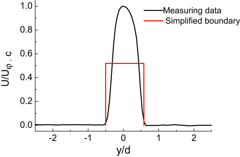
The breathing boundary for CFD simulation.
In this paper, results of manikin's breathing through mouth were presented, while it may become more complicated when the manikin breathes through nose. It can be more difficult to measure the exhaled flow since the two nostrils have an angle with the horizontal plane about 45° and an angle with the intervening angle of 30° between the vertical planes. The flow characteristics may be different for the interaction of the two jets. In addition, compared with a real human, the shape of the manikin's mouth was simplified. For the diversity of human, the shape of mouth when breathing is various and irregular, which may have an effect on the characteristics of the exhaled flow. All these need further research.
5. Conclusions
In this study, 2D TR-PIV was used to measure the exhaled flow. Since it is transient and periodic, the phase-averaged method was used to analyze the exhaled flow characteristics. The experiments were performed under isothermal and heated conditions. It can be concluded that:
-
(1)
TR-PIV measurement together with the phase-averaged method, can help obtain sound information of the breathing flow. When choosing the sampling frequency and the number of the instantaneous samples for each phase, a trade-off had to be made and it was suggested that the number of the instantaneous samples for each phase should be equal to or greater than 75.
-
(2)
The breathing boundary should be set with a velocity inlet of a sinusoidal function over time in CFD modeling. In exhalation process, as the mouth exit velocity profile was bell-shaped for each phase, and the radial velocity gradient was quite large. While the velocity profile can be considered as a constant for each phase of the inhalation process.
-
(3)
The exhaled flow showed different characteristics during each stage of the exhalation process. In the initial phase, a mushroom-shaped flow was observed for the isothermal condition, while this structure became asymmetric due to the thermal plume and thermal buoyancy under the heated condition. In the middle phase, the exhaled flow exhibited jet characteristics, yet it had some differences from a free jet. Under the heated condition, the diffusion angle was greater, the decay of the centerline velocity along the axis was different, and the exhaled flow had greater entrainment. In the final phase, the jet characteristics gradually disappeared, and the exhaled flow had a clear upwards trend under the heated condition, promoting contaminant diffusion.
-
(4)
The distribution of the vorticity was also different at different phases. A pair of vortices was formed besides the mushroom-shaped flow, and the vortex structure existed throughout the entire exhalation process. The exhaled flow had a large vorticity. In the initial phase, the distribution of the vorticity value was unique for the exhaled flow, with its maximum occurring in the center of the above-centerline and below-centerline parts. In other phases, it was similar to a free jet.
-
(5)
The exhaled flow showed clear turbulence characteristics. In the short time between exhalation and inhalation, the turbulence fluctuation was quite strong. The mean turbulence intensity was about 0.055 at the center of the exit in the first half of the exhalation process, while it was about 0.092 in the second half of the exhalation process.
These quantitative PIV results provided detailed information about boundary condition set and validation data for CFD simulations. The whole exhalation process were also presented in detail. Due to the difference between the manikin and human, further study is required.
Acknowledgments
The research presented in this paper was financially supported by the National Key Basic Research and Development Program of China (the 973 program) through grant number 2012CB720100.
References
- 1.Fabian P., McDevitt J.J., DeHaan W.H., Fung R.O., Cowling B.J., Chan K.H., Leung G.H., Milton D.K. Influenza virus in human exhaled breath: an Observational Study. Plos One. 2008;3:e2691. doi: 10.1371/journal.pone.0002691. [DOI] [PMC free article] [PubMed] [Google Scholar]
- 2.Milton D.K., Fabian M.P., Cowling B.J., Grantham M.L., McDevitt J.J. Influenza virus aerosols in human exhaled breath: particle size, culturability, and effect of surgical masks. PLoS Pathog. 2013;9:e1003205. doi: 10.1371/journal.ppat.1003205. [DOI] [PMC free article] [PubMed] [Google Scholar]
- 3.Papineni R.S., Rosenthal F.S. The size distribution of droplets in the exhaled breath of healthy human subjects. J. Aerosol Med. 1997;10:105–116. doi: 10.1089/jam.1997.10.105. [DOI] [PubMed] [Google Scholar]
- 4.Xu C., Nielsen P.V., Gong G., Liu L., Jensen R.L. Measuring the exhaled breath of a manikin and human subjects. Indoor Air. 2015;25:188–197. doi: 10.1111/ina.12129. [DOI] [PubMed] [Google Scholar]
- 5.Morawska L., Johnson G.R., Ristovski Z.D., Hargreaves M., Mengersen K., Corbett S. Size distribution and sites of origin of droplets expelled from the human respiratory tract during expiratory activities. J. Aerosol Sci. 2009;40:256–269. doi: 10.1016/j.jaerosci.2008.10.003. [DOI] [PMC free article] [PubMed] [Google Scholar]
- 6.Tang J., Noakes C., Nielsen P., Eames I., Nicolle A., Li Y. Observing and quantifying airflows in the infection control of aerosol- and airborne-transmitted diseases: an overview of approaches. J. Hosp. Infect. 2011;77:213–222. doi: 10.1016/j.jhin.2010.09.037. [DOI] [PMC free article] [PubMed] [Google Scholar]
- 7.Gao N., Niu J. Transient CFD simulation of the respiration process and inter-person exposure assessment. Build. Environ. 2006;41:1214–1222. doi: 10.1016/j.buildenv.2005.05.014. [DOI] [PMC free article] [PubMed] [Google Scholar]
- 8.Gupta J.K., Lin C.H., Chen Q. Risk assessment of airborne infectious diseases in aircraft cabins. Indoor Air. 2012;22:388–395. doi: 10.1111/j.1600-0668.2012.00773.x. [DOI] [PubMed] [Google Scholar]
- 9.Corbett E.L., Watt C.J., Walker N., Maher D., Williams B.G., Raviglione M.C. The growing burden of tuberculosis: global trends and interactions with the HIV epidemic. Arch. Intern. Med. 2003;163:1009–1021. doi: 10.1001/archinte.163.9.1009. [DOI] [PubMed] [Google Scholar]
- 10.Gupta J.K., Lin C.H., Chen Q. Characterizing exhaled airflow from breathing and talking. Indoor Air. 2010;20:31–39. doi: 10.1111/j.1600-0668.2009.00623.x. [DOI] [PubMed] [Google Scholar]
- 11.Bjørn E., Nielsen P.V. Dispersal of exhaled air and personal exposure in displacement ventilated rooms. Indoor Air. 2002;12:147–164. doi: 10.1034/j.1600-0668.2002.08126.x. [DOI] [PubMed] [Google Scholar]
- 12.Olmedo I., Nielsen P.V., Ruiz de Adana M., Jensen R.L., Grzelecki P. Distribution of exhaled contaminants and personal exposure in a room using three different air distribution strategies. Indoor air. 2012;22:64–76. doi: 10.1111/j.1600-0668.2011.00736.x. [DOI] [PubMed] [Google Scholar]
- 13.Olmedo I., Nielsen P.V., de Adana M.R., Jensen R.L. The risk of airborne cross-infection in a room with vertical low-velocity ventilation. Indoor Air. 2013;23:62–73. doi: 10.1111/j.1600-0668.2012.00794.x. [DOI] [PubMed] [Google Scholar]
- 14.Qian H., Li Y., Nielsen P.V., Hyldgaard C.E. Dispersion of exhalation pollutants in a two-bed hospital ward with a downward ventilation system. Build. Environ. 2008;43:344–354. [Google Scholar]
- 15.Gupta J.K., Lin C.H., Chen Q. Transport of expiratory droplets in an aircraft cabin. Indoor Air. 2011;21:3–11. doi: 10.1111/j.1600-0668.2010.00676.x. [DOI] [PubMed] [Google Scholar]
- 16.Villafruela J.M., Olmedo I., Ruiz de Adana M., Méndez C., Nielsen P.V. CFD analysis of the human exhalation flow using different boundary conditions and ventilation strategies. Build. Environ. 2013;62:191–200. [Google Scholar]
- 17.He Q., Niu J., Gao N., Zhu T., Wu J. CFD study of exhaled droplet transmission between occupants under different ventilation strategies in a typical office room. Build. Environ. 2011;46:397–408. doi: 10.1016/j.buildenv.2010.08.003. [DOI] [PMC free article] [PubMed] [Google Scholar]
- 18.Villafruela J.M., Castro F., José J.F.S., Saint-Martin J. Comparison of air change efficiency, contaminant removal effectiveness and infection risk as IAQ indices in isolation rooms. Energy & Build. 2013;57:210–219. [Google Scholar]
- 19.Hyldg rd C.-E. Dept. of Building Technology and Structural Engineering; 1994. Humans as a Source of Heat and Air Pollution. [Google Scholar]
- 20.Yan W., Zhang Y., Sun Y., Li D. Experimental and CFD study of unsteady airborne pollutant transport within an aircraft cabin mock-up. Build. Environ. 2009;44:34–43. [Google Scholar]
- 21.Yin Y., Gupta J.K., Zhang X., Liu J., Chen Q. Distributions of respiratory contaminants from a patient with different postures and exhaling modes in a single-bed inpatient room. Build. Environ. 2011;46:75–81. doi: 10.1016/j.buildenv.2010.07.003. [DOI] [PMC free article] [PubMed] [Google Scholar]
- 22.Zhao B., Zhang Z., Li X. Numerical study of the transport of droplets or particles generated by respiratory system indoors. Build. Environ. 2005;40:1032–1039. doi: 10.1016/j.buildenv.2004.09.018. [DOI] [PMC free article] [PubMed] [Google Scholar]
- 23.Gao N.P. CFD study of the thermal environment around a human body: a review. Indoor Built Environ. 2005;14:5–16. [Google Scholar]
- 24.Xu C., Nielsen P.V., Gong G., Jensen R.L., Liu L. Influence of air stability and metabolic rate on exhaled flow. Indoor air. 2015;25:198–209. doi: 10.1111/ina.12135. [DOI] [PubMed] [Google Scholar]
- 25.Nielsen P.V., Jensen R.L., Litewnicki M., Zajas J.J. Proceedings of the 9th International Conference & Exhibition of Healthy Buildings 2009. Syracuse; NY, USA: 2009. Experiments on the Microenvironment and Breathing of a Person in Isothermal and Stratified Surroundings. Paper 374. [Google Scholar]
- 26.Yao S., Guo Y., Jiang N., Liu J. An experimental study of a turbulent jet impinging on a flat surface. Int. J. Heat Mass Transf. 2015;83:820–832. [Google Scholar]
- 27.Marr D., Khan T., Glauser M. On particle image velocimetry (PIV) measurements in the breathing zone of a thermal breathing manikin. Ashrae Trans. 2005:299–305. [Google Scholar]
- 28.Marr D., Spitzer I., Glauser M. Anisotropy in the breathing zone of a thermal manikin. Exp. Fluids. 2008;44:661–673. [Google Scholar]
- 29.Cao G., Sivukari M., Kurnitski J., Ruponen M. PIV measurement of the attached plane jet velocity field at a high turbulence intensity level in a room. Int. J. Heat Fluid Flow. 2010;31:897–908. [Google Scholar]
- 30.Sandberg M. Whole-field measuring methods in ventilated rooms. HVAC&R Res. 2007;13:951–970. [Google Scholar]
- 31.Cao X., Liu J., Jiang N., Chen Q. Particle image velocimetry measurement of indoor airflow field: a review of the technologies and applications. Energy Build. 2014;69:367–380. [Google Scholar]
- 32.Cao X., Liu J., Pei J., Zhang Y., Li J., Zhu X. 2D-PIV measurement of aircraft cabin air distribution with a high spatial resolution. Build. Environ. 2014;82:9–19. [Google Scholar]
- 33.ASHRAE . American Society of Heating, Rifrigerating and Air Conditoning Engineers; Atlanta: 2007. Air Quality Within Commercial Aircraft. ANSI/ASHRAE Standard 161–2007. [Google Scholar]
- 34.Bjørn E. Dept. of Building Technology and Structural Engineering, Aalborg University; 2000. Simulation of Human Respiration with Breathing Thermal Manikin. [Google Scholar]
- 35.Höppe P. Temperatures of expired air under varying climatic conditions. Int. J. Biometeorol. 1981;25:127–132. doi: 10.1007/BF02184460. [DOI] [PubMed] [Google Scholar]
- 36.Ghahremanian S., Moshfegh B. Evaluation of RANS models in predicting low Reynolds, free, turbulent round jet. J. Fluids Eng. 2014:136. 011201. [Google Scholar]
- 37.Laverge J., Spilak M., Novoselac A. Experimental assessment of the inhalation zone of standing, sitting and sleeping persons. Build. Environ. 2014;82:258–266. [Google Scholar]
- 38.Zhu S., Kato S., Murakami S., Hayashi T. Study on inhalation region by means of CFD analysis and experiment. Build. Environ. 2005;40:1329–1336. [Google Scholar]
- 39.Guo Y., Jiang N., Yao S., Dai S., Liu J. Turbulence measurements of a personal airflow outlet jet in aircraft cabin. Build. Environ. 2014;82:608–617. [Google Scholar]
- 40.Gori F., Petracci I., Angelino M. Flow evolution of a turbulent submerged two-dimensional rectangular free jet of air. Average particle image velocimetry (PIV) visualizations and measurements. Int. J. Heat Fluid Flow. 2013;44:764–775. [Google Scholar]
- 41.Wang Xin, Lian Yuan. Experimental research on complex eddy viscosity modeling in turbulent boundary layer. Acta Mech. Sin. 2002;03(3):320–327. (in Chinese) [Google Scholar]
- 42.Wang Xinjun, Luo Jisheng, Zhou Heng. On the eddy viscosity model of periodic turbulent shear flows. Acta Mech. Sin. OCT. 2003;19(5):470–475. [Google Scholar]


