

Highlights
► Sensitivity analysis of enthalpy recovery wheels to atmospheric conditions. ► Sensitivity analysis of active desiccant wheels to regeneration temperature. ► Thorough analysis of the transport phenomena in solid desiccant air drying.
Keywords: Desiccant, Dehumidification, Enthalpy recovery
Abstract
Although Passive and active solid desiccant dehumidification have been increasingly investigated and applied in modern air-conditioning design, some discrepancies regarding the effectiveness and the psychrometric representation of the two processes can be found in the literature. Passive desiccant wheels are usually applied as an energy saving technique for vapor-compression cooling systems, unburdening the cooling coil from handling the humidity of outside ventilation air stream. In contrast, active desiccant wheels are designed to promote a thorough dehumidification of outside ventilation air, many times allowing for the use of an evaporative cooler and achieving an appreciable cooling effect, using only water as the refrigerant. The present work is comprised of a comparative study of the roles played by heat and mass transfer in passive and active adsorptive air dehumidification. The adequate definition of effectiveness for desiccant wheels is also discussed.
Nomenclature
- a
constant
- c
constant
- Cwr
wall specific heat (kJ/kg K)
- d
constant
- f
desiccant mass fraction
- Fi
characteristic potential
- h
convective heat transfer coefficient (kW/m2)
- hy
convective mass transfer coefficient (kg/m2 s)
- hv
heat of vaporization (kJ/kg)
- H
enthalpy of air (kJ/kg)
- L
length of the wheel (m)
air mass flow rate (kg/s)
- mw
mass of the wall (kg)
- Patm
atmospheric pressure (Pa)
- Pws
saturation pressure (Pa)
- Pwt
wetted perimeter of flow channel (m)
- Q
heat of adsorption (kJ/kg)
- t
time (s)
- T
temperature (°C)
- u
air flow velocity (m/s)
- Y
air absolute humidity (kg H2O/kg air)
- YL
adsorbed air layer absolute humidity (kg/kg air)
- W
desiccant humidity (kg of moisture/kg of desiccant)
- x
coordinate (m)
Greek letters
- λ1
auxiliary parameter
- λ2
auxiliary parameter
- H
desiccant wheel characteristic potential effectiveness
- ϕw
relative humidity of air layer
- ɛ
effectiveness
Subscripts
- 1
air
- ci
cold inlet
- co
cold outlet
- dw
desiccant wheel
- EA
Entering Apparatus (fan-coil)
- er
enthalpy recovery
- EXH
exhaust stream
- hi
hot inlet
- ho
hot outlet
- IA
Insufflated Air
- in
inlet
- LA
leaving apparatus (fan-coil)
- OA
outside air stream
- out
outlet
- RA
room air
- sat
saturation
- w
wall
Superscript
- *
non-dimensional
1. Introduction
The careful control of ambient air moisture content is of concern in many industrial processes, with diverse applications such as in metallurgic or pharmaceutical production. In the air-conditioning field, the increasingly concern with sick building syndrome has brought the humidity control into a new perspective. Underestimated ventilation rates usually result in poor indoor air quality, with a high concentration of volatile organic compounds, smoke, bacteria and other contaminants [1]. Epidemiological studies indicate a direct connection between inadequate levels of moisture and the incidence of allergies, in addition to infectious respiratory diseases. Events such as the outbreak of Legionella in 1976 and the more recent SARS (severe acute respiratory syndrome) shed a new light over indoor air quality control and regulations [2].
The standard procedure for reducing the concentration of contaminants is to increase the flow of fresh air, known as ventilation rate. In fact, the required fresh air volume per occupant/hour imposed by indoor air-quality standards has typically doubled over the last three decades [3], [4]. However, since the outside fresh air has to be brought to the thermal comfort condition, increased ventilation rates also imply increased thermal loads, which in turn will demand air chillers with increased cooling capacity. Accordingly, there is a trade-off between indoor air quality and energy consumption, which is also of main concern of private and public sectors.
All-air systems usually employ multi-zone air-conditioning equipment, with individual reheat coils. Separate single ducts from the air-handling unit are distributed to each room, which is individually controlled. When the room air humidity exceeds a limit value, the humidistat takes control of the cooling coil, calling for additional cooling so as to dehumidify the air to the desired level. At this point, the air is excessively cold to be supplied to the room, which causes the thermostat to set off the reheat coil, with the objective of bringing the air temperature back to the comfort condition, as depicted in Fig. 1 . The steepness of the room sensible heating ratio, represented by the dashed line, prevents the fan-coil process (curve EA–LA) to intersect it, which can only be accomplished by the reheat process. Although it provides a satisfactory individual control of each zone, this constitutes a very energy wasteful design, since the air is continuously cooled and reheated. Moreover, it requires both temperature and humidity sensors and controls, which might represent a significant increase to the total cost of the system.
Fig. 1.

Psychrometric representation of standard air-conditioning system.
In addition, the different kinematics of heat and mass transfer makes it very difficult for the humidistat to respond as fast as the thermostat, many times resulting in an ineffective control. The strategy of bringing the air temperature value forth and back is an evidence of the cooling coil inability to simultaneously handle the sensible and the latent components of the thermal load [5].
The previous reasoning expresses a favorable scenario for the application of air dryers, particularly solid sorbent dryers. Adsorption is primarily used for component separation from a gaseous mixture, and is widely employed in the chemical industry. The main advantage is that the material pore size can be designed for selective adsorption of a given component, allowing even trace amounts to be removed. In air-conditioning systems, silica-gel has been used to remove the air humidity to an acceptable level, unburdening the cooling coil from the dehumidification task. Silica-gel is a form of silicon dioxide derived from sodium silicate and sulfuric acid, which has good affinity to water vapor and an adsorbing capacity of as much as 40% of its own weight. It can be manufactured as a substrate, and applied as a coating to a cylindrical drum, fitted with a micro-channel mesh. This equipment is often referred to as a desiccant wheel. The air dehumidification can be passive or thermally activated, as explained in the next section.
Although the modeling of desiccant wheels has been addressed by many publications [6], [7], [8], [9], [10], [11], [12], [13], [14], [15], [16], [17], [18], the discussion about the definition of efficiency for desiccant wheels is yet to be settled [19]. The mathematical modeling used to simulate the dynamic behavior of the desiccant wheel [16], [17], [18] is briefly described in the next section.
2. The mathematical modeling of air drying by solid desiccants
The modeling of the desiccant wheel is described by the following system of partial differential equations. The first and second equations account for mass balances within the flow channel and the desiccant layer, respectively. Similarly, the third and fourth equations represent energy balances within the flow channel and the desiccant layer, respectively.
| (1) |
The independent variables are the non-dimensional position
| (2) |
and the non-dimensional time
| (3) |
with the auxiliary parameters given by
| (4) |
| (5) |
Q is the heat of adsorption, given by [20],
| (6) |
and the enthalpy of the air H1 can be written as [21]
| (7) |
where
There are four equations to be solved [1], and five unknowns, T 1, T w, W, Y and Y L. The equation that relates the absolute humidity of the air in equilibrium Y L (or its relative humidity) to the moisture content and the temperature of the solid is the adsorption isotherm, and for silica gel RD is given by [22]
| (8) |
the pressure of saturated water vapor given by
| (9) |
and the absolute humidity at the adsorbed layer given by
| (10) |
The periodic nature of the problem implies an iterative procedure. Both initial distributions of temperature and humidity within the solid are guessed, and Eq. [1], assume the form of tridiagonal matrices, as a result of the discretization using the finite-volume technique [23], with a fully implicit scheme to represent the transient terms and an upwind formulation for the convective terms. By the end of the cycle, both calculated temperature and moisture fields are compared to the initially guessed. If there is a difference in any nodal point bigger than the convergence criteria established for temperature and moisture content,
| (11) |
| (12) |
the procedure is repeated, using the calculated fields as new guesses for the initial distributions. The average “hot outlet” enthalpy during a cycle is defined as
| (13) |
Since the wheel is to store neither energy nor mass after a complete cycle,
| (14) |
or else
| (15) |
the normalized difference between the two sides of equation [15] is defined as the Heat Balance Error (HBE):
| (16) |
All cases exhibited extremely low values of HBE (less than 0.01%) at moderate values of grid size and temperature and mass convergence criteria. The results were obtained for a grid of 91 points with a time interval δt of 10−3, with a HBE of 0.0022% after 173 iterations.
Although the mathematical model previously described is suitable for both passive and active dehumidification, the outcome of the simulation and the roles played by heat and mass transfers are substantially distinct in each case.
Consider Fig. 2(a), which shows a scheme of a passive desiccant wheel in an air-conditioning system. It operates swinging between the outside air and the exhaust room streams. The outside air stream is forced through the wheel, flowing through the micro-channels as it exchanges heat and mass with the desiccant coated walls. Since the objective is to recover enthalpy, the outside air stream is expected to simultaneously transfer heat and mass to the desiccant material. On the other side, when the room exhaust stream is forced through the wheel, it cools and dries the desiccant coated walls, dumping the heat and mass back to the atmosphere. As enthalpy is to be recovered, is expected some enthalpy storage within the desiccant material during the adsorptive period, which should exactly match the enthalpy deficit during the desorptive period, in steady state operation. Accordingly, the outside air stream is not expected to undergo an isenthalpic process when submitted to passive desiccant dehumidification. In fact, it is expected that the outside air stream will experience an enthalpy decrease between the wheel inlet and outlet, as depicted by the dashed line in Fig. 3 .
Fig. 2.
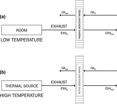
Schematic representation of active and passive dehumidification.
Fig. 3.

Psychrometric description of active and passive dehumidification.
Moreover, it should be observed that passive desiccant wheels exhibit a limited dehumidification capacity. This can be explained by observing that desorption, which is an endothermic process, is promoted by the low temperature room exhaust stream. In a similar way, at the opposite process, the outside air stream cooling occurs simultaneously to the adsorption. Accordingly, the cooling process is rather ineffective, since adsorption is an exothermic process. It can be concluded that the heat and the mass transfers play off-setting roles from the enthalpy recovery viewpoint. Heat and mass are expected to have the same direction of migration, from the air to the desiccant felt during adsorption, with this direction being reversed during desorption. The enthalpy recovery effectiveness can be defined as [16]
| (17) |
If lower levels of absolute humidity are to be achieved, the dehumidification has to be thermally activated, as depicted in Fig. 2(b). When compared to passive wheels, active desiccant wheels contain a greater weight of silica-gel, or even uses a different desiccant material, with stronger affinity to water vapor. A high temperature regeneration stream provides the sensible energy required to purge the humidity from the solid, allowing for a thorough dehumidification. During desorption, heat is transferred from and mass is transferred to the air stream, whereas during adsorption these directions are reversed. As a result, an isenthalpic process is expected when air is submitted to active desiccant dehumidification, such as depicted by the continuous line in Fig. 3. Since the efficiency as described by Eq. [17] would be null, Eq. [18] has been proposed [14], [15] to represent the desiccant wheel efficiency. However, since it does not carry any enthalpy terms, it can only represent a dehumidification effectiveness,
| (18) |
The ideal outside air humidity at the wheel outlet would be zero. The deviation of the isenthalpic behavior was suggested as a measure of inefficiency [24], as calculated by Eq. [3]. The adequacy of this definition will be addressed at the next section.
| (19) |
3. Results
3.1. Passive dehumidification
The analysis will be first carried out for passive desiccant wheels, considering different conditions for the room exhaust stream, as described by cases (1)–(3) in Table 1 . Cases (1)–(3) have increasing temperatures and decreasing humidities for the room exhaust stream, in such a way that the enthalpy is kept constant. The outside air stream condition is kept constant in all situations. Referring to Fig. 2(a), cases (1)–(3) in Table 1 correspond to different room exhaust conditions (EXHin), whereas state OAin corresponds to the condition of outside air. The processes undergone by the outside air ventilation stream are shown in Fig. 4 . All results show that the outside air stream enthalpy is significantly reduced, as it would be expected from an enthalpy recovery technique. The deviation from the isenthalpic behavior is indeed a measure of the enthalpy recovery efficiency. Moreover, the enthalpy recovery for cases (1)–(3) is the same, even though they represent different wheel inlet values for the room exhaust stream humidity and temperature. The physical reasoning behind this result is the aforementioned offsetting roles played by heat and mass transfers during the enthalpy recovery. The same behavior is observed, that is, all the cases exhibit the same value for the enthalpy at the outside air stream outlet. In addition, it can be inferred by observing (Fig. 4) that the enthalpy recovery capacity is limited. Comparing the outlet states from (1) to (3), it is apparent that a greater humidity reduction (i.e. latent energy recovery) is associated to a less significant temperature drop (i.e., sensible energy recovery). Accordingly, the greater is the humidity reduction, the lesser will be the temperature drop of the outside air stream across the desiccant wheel. Moreover, it should be observed that adsorption is an exothermic process, and the released heat hinders the airstream cooling. This result represents an opportunity for combining desiccants with a phase change material, which could act as a heat sink which absorbs the released heat of adsorption, allowing for a more significant sensible energy recovery [25], [26]. This ideal process would be represented by the dashed line in Fig. 4, leading to state OApc.
Table 1.
Influence of room condition over the enthalpy recovery.
| TEXHin (°C) | YEXHin (kg/kg) | HEXHin (kJ/kg) | TOAin (°C) | YOAin (kg/kg) | |
|---|---|---|---|---|---|
| Case 1 | 22.0 | 0.0116 | 51.6 | 35.0 | 0.0253 |
| Case 2 | 25.0 | 0.0104 | 51.6 | 35.0 | 0.0253 |
| Case 3 | 29.0 | 0.0088 | 51.6 | 35.0 | 0.0253 |
Fig. 4.

Influence of room conditions over the enthalpy recovery, conditions of Table 1.
Table 2 shows a similar analysis, however taking different outside air conditions (in such a way the enthalpy is held constant) and a fixed condition at inlet for the air exhaust stream, as this is the most common situation in air-conditioning design. The results depicted in Fig. 5 show that the enthalpy recovery is constant for cases (OA1) to (OA3), which represent fairly distinct values for outside air temperature and humidity. Accordingly, the enthalpy recovery efficiency, as described by Eq. [1] is oblivious to the outside air condition.
Table 2.
Influence of the atmospheric condition over the enthalpy recovery.
| TEXHin (°C) | YEXHin (kg/kg) | TOAin (°C) | YOAin (kg/kg) | HOAin (kJ/kg) | |
|---|---|---|---|---|---|
| Case 1 | 25.0 | 0.0099 | 32.0 | 0.0212 | 56.7 |
| Case 2 | 25.0 | 0.0099 | 35.0 | 0.0200 | 56.7 |
| Case 3 | 25.0 | 0.0099 | 29.0 | 0.0025 | 56.7 |
Fig. 5.
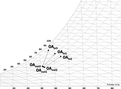
Influence of atmospheric conditions over the enthalpy recovery, Table 2.
3.2. Active dehumidification
As for active desiccant rotors, Table 3 shows four different conditions for the regeneration air inlet, with the respective outlet conditions shown in Fig. 6 . The outside air inlet condition is kept fixed for all four cases. It can be seen that all cases exhibit an isenthalpic behavior (with a small deviation) between inlet and outlet. This result supports the cooperating roles played by heat and mass transfers in active dehumidification. Fig. 7 shows that it takes a regeneration temperature of 120 °C to produce an appreciable deviation from the isenthalpic process. It is an indication that the maximum moisture removal capacity of the material has been reached. Fig. 6 shows that the efficiency, as described by Eq. [3] is of limited use, because deviations such as exhibited by state (1) would yield a value for the efficiency greater than 100%. The nearly isenthalpic behavior for air dehumidification by active desiccant wheels has been previously observed in experimental [27] and numerical investigations [28].
Table 3.
Influence of the regeneration temperature over the dehumidification effectiveness.
| Texhin (°C) | Yexhin (kg/kg) | TOAin (°C) | YOAin (kg/kg) | |
|---|---|---|---|---|
| Case 1 | 50.0 | 0.0120 | 35.0 | 0.0253 |
| Case 2 | 60.0 | 0.0120 | 35.0 | 0.0253 |
| Case 3 | 70.0 | 0.0120 | 35.0 | 0.0253 |
| Case 4 | 80.0 | 0.0120 | 35.0 | 0.0253 |
| Case 5 | 120.0 | 0.0120 | 35.0 | 0.0253 |
Fig. 6.

Influence of the regeneration temperature over the active dehumidification, Table 3.
Fig. 7.
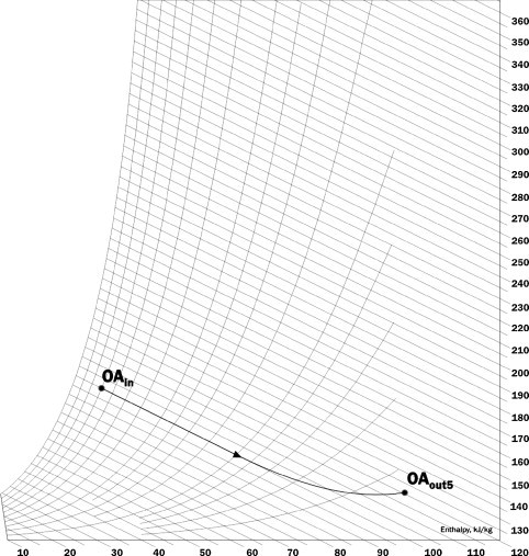
Excessive regeneration temperature in active dehumidification, case 5, Table 3.
An alternative solution for the process undergone by the outside air stream through an active desiccant wheel can be alternatively obtained by transforming the conservation equations into a non-linear system of hyperbolic partial differential equations, which are solved using the wave shock method [29], [30], [31]. The solution leads to Riemann invariants, described by Eqs. (20) and (21) which are named characteristic potentials F i. Then, values for the potentials effectiveness of the desiccant wheel are assigned, allowing for the potentials F 1,OAout and F 2,OAout to be evaluated using Eqs. (22) and (23). The temperature T OAout and the humidity Y OAout are then recovered from the potentials F 1,OAout and F 2,OAout, which form a system of non-linear algebraic equations.
| (20) |
| (21) |
| (22) |
| (23) |
This solution has been applied in several desiccant cycle modeling [31], [32], [33], as well as in professional simulation tools [34]. Moreover, it has been compared to experimental results, exhibiting a reasonable agreement [35]. Table 4 shows the results for the values of η F1 and η F2 respectively set to 0.05 and 0.95, which correspond to a high performance desiccant wheel [31]. It can be observed a maximum of deviation of 5% from the isenthalpic behavior, for T EXHxin = 80 °C.
Table 4.
| TEXHin (°C) | TOAin (°C) | YOAin (kg/kg) | hOAin (kJ/kg) | TOAout (°C) | YOAout (kg/kg) | hOAout (kJ/kg) |
|---|---|---|---|---|---|---|
| 70.0 | 35.0 | 0.012 | 67.0 | 54.8 | 0.0057 | 70.0 |
| 80.0 | 35.0 | 0.012 | 67.0 | 60.2 | 0.0043 | 71.7 |
A comparison between the dehumidifying capacities of passive and active wheels is provided in Fig. 8 . It can be observed a linear dependence between the inlet and outlet absolute humidities. It is also shown that passive desiccant wheels exhibit a significantly lower dehumidifying capacity than active wheels, particularly for an increased regeneration temperature.
Fig. 8.

A comparison of active and passive dehumidifying capacities.
4. Conclusion
The present work discusses the definitions for effectiveness of active and passive desiccant wheels, as well as the physical reasoning underlying the enthalpy recovery and active dehumidification processes. For passive dehumidification, it was concluded that heat and mass transfer have conflicting influences over the enthalpy recovery, making the enthalpy recovery effectiveness oblivious to the atmospheric conditions. Accordingly, an increase in the outside air temperature will imply in a greater contribution of the sensible energy to the total enthalpy recovery, at the expense of a lesser contribution of the latent energy. Conversely, an increase in the outside air humidity will reverse this scenario, imposing a greater importance of the latent energy contribution. In any case, the enthalpy recovery effectiveness is properly described by Eq. [17].
As for the active dehumidification, it was shown that heat and mass transfer have cooperating effects, with the dehumidification capacity increasing with the regeneration temperature, until the maximum dehumidification capacity has been reached. The isenthalpic nature of the process has been confirmed, which prevents a definition of efficiency based on enthalpy, as it occurs for evaporative cooling systems [21]. The results show that silica-gel accomplishes a thorough air dehumidification even for a low reactivation temperature, which allows for the use of solar energy or low grade waste heat to drive the system.
References
- 1.Godish T. Lewis Publishers; Boca Raton, FL: 2001. Indoor Environmental Quality. [Google Scholar]
- 2.Straube J.F. Moisture organisms health effects. In: Trechsel H., Bomberg M.T., editors. Moisture Control in Buildings. West Conshohocken; ASTM: 2009. [Google Scholar]
- 3.American Society of Heating, Refrigerating and Air-Conditioning. Ventilation for Acceptable Indoor Air Quality, ASHRAE Standard 62-1981, 1981.
- 4.American Society of Heating, Refrigerating and Air-Conditioning. Ventilation for Acceptable Indoor Air Quality, ASHRAE Standard 62-2005, 2005.
- 5.Pita E.G. 4th ed. Prentice-Hall; 2002. Air Conditioning Principles and Systems. [Google Scholar]
- 6.Close D.J. Characteristic potentials for heat and mass transfer processes. International Journal of Heat and Mass Transfer. 1983;26:1098–1102. [Google Scholar]
- 7.Shen C.M., Worek W.M. The effect of wall conduction on the performance of regenerative heat exchangers. Energy. 1992;17:1199–1213. [Google Scholar]
- 8.Ge T.S., Li Y., WangY.J., Dai R.Z. A review of the mathematical models for predicting rotary desiccant wheel. Renewable and Sustainable Energy Reviews. 2008;12:1485–1528. [Google Scholar]
- 9.Sphaier L.A., Worek W. The effect of axial diffusion on enthalpy wheels. International Journal of Heat and Mass Transfer. 2006;49:1412–1419. [Google Scholar]
- 10.Zhang X.J., Dai Y.J., Wang R.Z. A Simulation study of heat and mass transfer in a honeycomb structure rotary desiccant dehumidifier. Applied Thermal Engineering. 2003;23:989–1003. [Google Scholar]
- 11.Shang W., Besant R.W., Theoretical Experimental methods for the sensible effectiveness of air-to-air energy recovery wheels. HVAC&R Research. 2008;14:373–396. [Google Scholar]
- 12.Shang W., Besant R.W. Effectiveness of desiccant coated regenerative wheels from transient response characteristics and flow channels-part I. HVAC&R Research. 2008;15:329–345. [Google Scholar]
- 13.Stabat P., Marchio D. Heat and mass transfer modeling in rotary dehumidifiers. Applied Energy. 2009;86:762–771. [Google Scholar]
- 14.Niu J.L., Zhang L.Z. Effects of wall thickness on the heat and moisture transfers in desiccant wheels for air dehumidification and enthalpy recovery. International Communications in Heat and Mass Transfer. 2002;29(2):255–268. [Google Scholar]
- 15.Niu J.L., Zhang L.Z. Performance comparisons of desiccant wheels for air dehumidification and enthalpy recovery. Applied Thermal Engineering. 2002;22:1347–1367. [Google Scholar]
- 16.Nobrega C.E.L, Brum N.C.L. Modeling and simulation of heat and enthalpy recovery wheels. Energy. 2009;34:2063–2068. [Google Scholar]
- 17.Nobrega C.E.L., Brum N.C.L. Influence of isotherm shape over desiccant cooling cycle performance. Heat Transfer Engineering. 2009;30(4):302–308. [Google Scholar]
- 18.Nobrega C.E.L.N.C., Brum L. A graphical procedure for desiccant cooling cycle design. Energy. 2011;36:1564–1570. [Google Scholar]
- 19.Mandegari M.A., Pahlavanzadeh H. Introduction of a new definition of desiccant wheels. Energy. 2009;34:797–803. [Google Scholar]
- 20.San J.Y. Heat and Mass transfer in a two-dimensional cross flow regenerator with a solid conduction effect. International Journal of Heat and Mass Transfer. 1993;36(3):633–643. [Google Scholar]
- 21.Kuehn T.H., Ramsey J.W., Threlkeld J.L. 3rd ed. Prentice-Hall; Upper Saddle River: 1998. Thermal Environmental Engineering. [Google Scholar]
- 22.Pesaran A.A., Mills A.F. Moisture transport in silica gel packed beds-part I. International Journal of Heat and Mass Transfer. 1987;30:1051–1060. [Google Scholar]
- 23.Patankar S. Hemisphere Publishing Co.; Boston, MA: 1980. Numerical Heat Transfer and Fluid Flow. [Google Scholar]
- 24.Sphaier L.A., Nobrega C.E.L. Parametric analysis of components effectiveness on desiccant cooling cycle performance. Energy. 2012;38:1564–1570. [Google Scholar]
- 25.Rady M., Pessac F. Heat and mass transfer in a composite bed or silica-gel and macro encapsulated PCM for dehumidification. Proceedings of the 5th European Thermal Sciences Conference, EUROTHERM; Eindhoven, the Netherlands; 2008. [Google Scholar]
- 26.Rady M. Heat and mass transfer in a composite bed or silica-gel and macro encapsulated PCM for performance of dehumidification of desiccant beds composed of silica-gel and thermal energy storage particles. Heat and Mass Transfer. 2009;45(5):545–561. [Google Scholar]
- 27.Kanoglu M., Çarpinlioglu M.C., Yildirim M. Energy and energy analyses of an experimental open cycle desiccant cooling Systems. Applied Thermal Engineering. 2004;24:919–932. [Google Scholar]
- 28.Niu J.L., Zhang L.Z., Kho H.G. A pre-cooling Munters environmental control desiccant cooling cycle in combination with chilled-ceiling panels. Energy. 2003;28:275–292. [Google Scholar]
- 29.Bulck E.V., Mitchell J.W., Klein S.A. Design theory for rotary heat and mass exchangers – I: wave analysis of rotary heat and mass exchangers with infinite transfer coefficients. International Journal of Heat and Mass transfer. 1985;28(8):1575–1586. [Google Scholar]
- 30.Bulck E.V., Mitchell J.W., Klein S.A. Design theory for rotary heat and mass exchangers – II: effectiveness-number of unit transfers analysis. International Journal of Heat and Mass Transfer. 1985;28(8):1587–1595. [Google Scholar]
- 31.Panaras G., Mathioulakis E., Belessotis V. Achievable working range for all-desiccant air-conditioning systems under specific space comfort requirements. Energy and Buildings. 2007;39:1055–1060. [Google Scholar]
- 32.Niu J.L., Zhang Z.L., Kho H.G. Energy saving potential of chilled-ceiling combined with desiccant cooling in hot and humid climates. Energy and Buildings. 2002;34:487–495. [Google Scholar]
- 33.Niu J.L., Zhang Z.L., Kho H.G. A pre-cooling munters environmental control desiccant cooling cycle in combination with chilled-ceiling panels. Energy. 2003;28:275–292. [Google Scholar]
- 34.Howe R. Energy Lab; 1983. Rotary Desiccant Dehumidifiers, TRNLIB, Libraries of User-Written TRNSYS Components. [Google Scholar]
- 35.Panaras G., Mathioulakis G.E., Belessotis V., Kyriakis N. Experimental validation of a simplified approach for desiccant wheel model. Energy and Buildings. 2010;(42):1719–1725. [Google Scholar]