Abstract
Full-scale experiments and CFD simulations were performed to study potential inter-cubicle airborne transmissions through a shared anteroom due to the hinged door opening. When doors are closed, current negative pressure designs are effective for the containment of airborne pathogens in the 'dirty' cubicle with an index patient. When the 'dirty' cubicle door is open, airborne agents can move into the other 'clean' cubicle via the shared anteroom. As the door being opened or closed, the door sweeping effect is the main source of the two-way airflow and contaminant exchange through the doorway. When the dirty cubicle door remains fully open, temperature difference and concentration gradient across the doorway induce the two-way buoyancy-driven flow and transport of airborne agents across the doorway. The longer the dirty cubicle door remains fully open (10 s, 30 s or 60 s) or the smaller the air change rate (34–8.5 ACH for each cubicle), the more airborne pathogens are being transported into the 'clean' cubicle and the longer time it takes to remove them after the door is closed. Keeping the door completely open is potentially responsible for the majority of inter-cubicle transmissions if its duration is much longer than the duration of door motion (only 3 s). Our analyses suggest a potential inter-cubicle infection risk if the shared anteroom is used for multiple isolation cubicles. Decreasing the duration of door opening, raising air change rate or using a curtain at the doorway are recommended to reduce inter-cubicle exposure hazards.
Keywords: Inter-cubicle airborne transmission, Isolation room, Door motion, Computational fluid dynamic (CFD) simulation, Full-scale field experiment
Highlights
-
•
Potential inter-cubicle airborne transmission through a shared anteroom was found.
-
•
Both full-scale experiments and CFD simulations were performed to ensure this issue.
-
•
As the door being opened or closed, door motion induces two-way flow across doorway.
-
•
As the door remains fully open, it is due to temperature difference across doorway.
-
•
Longer door-opening duration and smaller air change rate produce more risk.
1. Introduction
Respiratory infectious diseases, such as tuberculosis (TB), influenza, and severe acute respiratory syndrome (SARS), threaten lives worldwide. For example, in the early 21st century, more than 8000 cases of SARS were reported, resulting in 774 deaths [1]. Infection transmission in hospitals for such highly infectious diseases is an important public health issue. Besides direct or indirect contact transmissions [2], respiratory infectious diseases can also be spread by airborne transmission of droplet nuclei over large distance. The Centers for Disease Control and Prevention (CDC) includes the use of administrative measures and engineering controls among its recommendations for reducing exposure risk in health care facilities [3]. Negative pressure isolation cubicles are usually built to accommodate patients in which a slightly negative pressure relative to the surrounding area may effectively prevent infectious agents from escaping out of isolation cubicles [3], [4]. Some design guidelines are widely accepted [3], [4]. US CDC guidelines and relevant international standards are in agreement with respect to requiring a ventilation rate of 12 air change rates per hour (ACH) [3], [4].
However if an isolation cubicle door is open, the negative pressure differential across the doorway may decrease to small values and the effectiveness of the containment measure may not be maintained [5], [6], [7], [8], [9], [10], [11], [12]. To reduce the risk of infectious droplets and particles escaping into the corridor, an anteroom is commonly added to separate the cubicle and the corridor. With a higher pressure than the isolation cubicle and lower pressure than the corridor, the anteroom acts as an airlock. Tung et al. [6] reported that, if the isolation cubicle door is open and the air velocity through the doorway is less than 0.2 m/s, risk of droplet nuclei leakage into the anteroom is high. Small-scale experiments and theoretical models [7], [8] confirmed that the opening and closing motion of hinged doors can induce transient airflows and turbulence close to the doorway, followed by air exchange and the transport of airborne particles into the anteroom through the doorway. In addition, health care worker (HCW) movement is a significant factor in the spread of airborne pathogens and particles [9], [10], [11], [12], [13], [14], [15], [16], [17], [18], [19].
It is difficult to obtain quantitative and high-quality experimental data with meaningful spatial and temporal resolution on how door opening and HCW movement affecting the containment effectiveness of isolation cubicles [9], [10], [11]. Rydock and Eian [9] carried out tracer gas experiments in which sulfur hexafluoride (SF6) was released at the patient bed position and allowed to mix in the room for 2 min before the release technician exited the room into the anteroom. The technician waited an additional 3 min in the anteroom before entering the adjacent corridor. Subsequently, SF6 was readily detected in both the anteroom and the corridor, indicating tracer gas leakage into the anteroom and corridor during HCW movement. Johnson et al. [10] also reported that containment efficiency was greatly reduced during HCW movement into and out of an expedient isolation enclosure. After fluorescent microspheres were released in the isolation cubicle (particle diameter of 2 μm), Adams et al. [11] measured airborne concentrations in the anteroom and at the corridor–anteroom door with and without HCW movement. They found that containment efficiency rose with greater negative pressure differential, and fell with an increase in human traffic.
Use of a dynamic mesh technique combined with computational fluid dynamics (CFD) simulations [12], [13], [14], [15], [16], [17] has recently allowed simulation of transport of infectious agents induced by door motion and human movement. Using large eddy simulations, Choi and Edward [12] found that for a non-hospital environment the motion of hinged door and realistic human walking did enhance compartment-to-compartment contaminant transport between two rooms through the doorway and a shared vestibule. Poussou et al. [13] and Mazumdar et al. [14] numerically found that human-movement-induced wake may carry contaminant to positions far from the source location in an airplane cabin. For hospital isolation rooms with higher air change rates, some published studies verified that the velocity and pressure field were significantly affected by human motion and/or door motion [15], [16], [17], [18], [19]. However there was only a small change in airborne transmission of airborne agents, and the risk quickly returned to its original level after the door was closed and HCW motion stoped [15], [16], [17]. Hang et al. [17] reported ventilation design and air change rates in a six-bed isolation room affected airborne transmission much more than human motion. Goldasteh [18] and Wang and Chow [19] found that human motion can significantly influence particle re-suspension and particle dispersion in the isolation room.
Most airborne transmissions are via dispersion of droplets/particles. Previous studies have confirmed that droplets/particles of different sizes are released from breathing, coughing, or sneezing and then undergo evaporative water loss in the air. There have been a number of studies on evaporation, dispersion and deposition of respiratory droplets as well as tracer gas dispersion in various indoor environments under different ventilation systems [19], [20], [21], [22], [23], [24], [25], [26], [27], [28], [29], [30], [31], [32], [33], [34], [35], [36], [37], [38]. Larger particles (diameter >20 μm) may rapidly deposit onto wall surfaces because the force of gravity is more significant than ventilation [19], [20], [21], [22], [23], [24], [25], [26], [27], [37]; Smaller particles (0.5–10 μm) may remain suspended for a long time and contribute to disease transmission over greater distances, thus their transport process is similar with those of gaseous agents [24], [25], [26], [27], [37], [38]. Both fine particles and gaseous pathogens are significantly influenced by ventilation rates and airflow patterns [19], [20], [21], [22], [23], [24], [25], [26], [27], [28], [29], [30], [31], [32], [33], [34], [35], [36], [37], [38]. Yin et al. [38] experimentally studied an one-bed isolation room under the mixing or displacement ventilation system. They found that fine particles (diameter 1 μm and 3 μm) and tracer gas can generate similar contaminant distributions in most region of the ward, except in the areas close to the contaminant source and the exhaust adjacent to the restroom, where the flow may be unstable.
Two or more isolation cubicles may share the same anteroom to reduce construction costs. However few studies have been carried out to evaluate the risk of inter-cubicle airborne transmission via the shared anteroom if hinged door motion and/or HCW movement occur. Our objective was to confirm and quantify the mechanism of inter-cubicle airborne transmission induced by the hinged door motion and the duration of door opening. As a start, this paper first disregards HCW movement and only investigates inter-cubicle transport of tracer gas as a surrogate for very fine droplet nuclei. 2, 3 introduce full-scale experiments and CFD setups respectively. Section 4 presents results and discussions. Finally the conclusions are drawn in Section 5.
2. Experimental setups in full-scale measurements
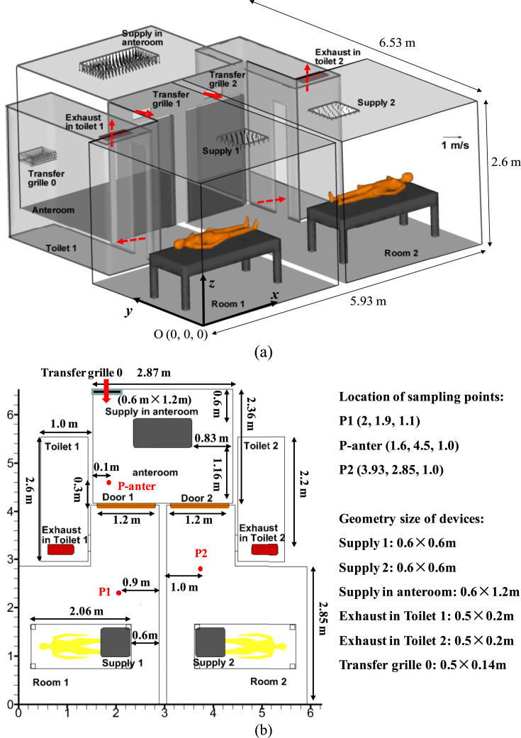
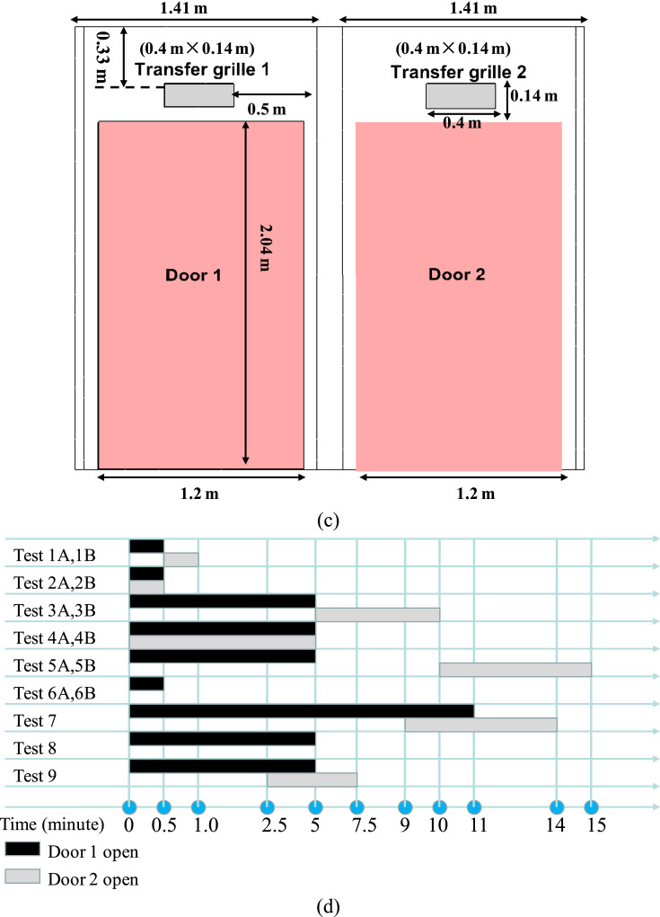
We carried out a series of full-scale field measurements in the Christian Medical Centre (CMC) Hospital, Hong Kong in 2010. Two neighboring isolation cubicles are located in Ward 8B, as shown in Fig. 1 a–c. In these experiments, tracer gas (SF6) was continuously released from the mouth of a thermal manikin in Cubicle 850A (named as Room 1, 'dirty room'). There was no tracer gas source in Cubicle 849 which is named as Room 2 ('clean room'). Each cubicle has its own toilet (Toilet 1 and 2) but uses a shared anteroom. Exhausts 1 and 2 are located in the ceiling of Toilets 1 and 2. The door in 'dirty' Room 1 is referred to as Door 1, and that in 'clean' Room 2 as Door 2. Each door is 1.2 m wide and 2.04 m tall (Fig. 1c). Above the two doors there are two air transfer grilles (Transfer grilles 1 and 2, see Fig. 1c) connecting two cubicles with the shared anteroom. There are downward supply diffusers in each cubicle, i.e. Supply 1 in Room 1, and Supply 2 in Room 2. In the anteroom, there is also a downward supply diffuser on the ceiling and an air transfer grille connected to the corridor (Transfer grille 0).
Fig. 1.
(a–c) Model description of two isolation cubicles with a shared anteroom. (d) Nine sets of test cases in field measurements.
The volumetric flow rates were measured by an electronic balometer (Model: ALNOR with APM 150 Meter) (Table 1 ). The measured volumetric flow rates through the supply in the anteroom, Transfer grille 0, Supply 1 and 2 were 0.354 m3/s, 0.080 m3/s, 0.089 m3/s and 0.043 m3/s respectively. Wind speed at two exhausts in Toilet 1 and 2 and Transfer grilles 1 and 2 was measured at nine points by using an air velocity meter (Model: TSI 8386A-M-GB), and an average air speed was obtained to estimate the air flow rate. Because the quality of such calculated flow rates is poor, this paper only uses the measured supply flow rates from the electronic balometer to calculate air change rates, which are 85 ACH, 27 ACH and 39 ACH for the anteroom, Room 1 and Room 2 respectively. These are much larger than the CDC specified value of 12 ACH [3], but such larger flow rates are commonly adopted in isolation wards of Hong Kong.
Table 1.
Ventilation parameters in full-scale field experiments and CFD simulations.
| Flow rates for supplies | Supply in anteroom | Transfer grille 0 from the corridor | Supply 1 in Room 1 | Supply 2 in Room 2 |
|---|---|---|---|---|
| Dimensions (cm) | 1.2 m × 0.6 m | 0.5 m × 0.14 m | 0.6 m × 0.6 m | 0.6 m × 0.6 m |
| Q-measured data (m3/s) | 0.354 | 0.080 | 0.089 | 0.043 |
| Q -defined in CFD (m3/s) | 0.354 | 0.080 | 0.066 | 0.066 |
| Air change rate in each location | Anteroom | Room 1 | Toilet 1 | Room 2 | Toilet 2 |
|---|---|---|---|---|---|
| Volume (m3) | 18.35 | 20.12 | 9.51 | 20.12 | 9.51 |
| Measured ACH | 85 ACH | 27 ACH | 39 ACH | ||
| ACH in CFD | 34 ACH | 34 ACH | |||
The concentration was continuously monitored by multipoint sampler/doser Type 1302 & 1303 (Brüel & Kjær, Denmark) at four sampling points (Fig. 1b–c), i.e. P1, P2, P-anter, one point near and below Supply 1. Each sample was collected within about three minutes. As shown in Fig. 1d, nine sets of experiments were performed according to the mode and duration of door opening. In Fig. 1d, the time unit is minute, and is not to scale. Prior to each test, all doors were closed for about 10 minutes to approximate conditions of equilibrium.
3. CFD setups in numerical modeling
3.1. Modeling door motion in CFD simulations
In all CFD simulations, only Door 1 is opened for a while (10 s, 30 s or 60 s). It is assumed for Door 1 to take 3 s to move from the closed state (0°) to fully open (90°). Similarly it takes 3 s to close from 90° to 0°. As shown in Fig. 2 a, the angular velocity of the sweeping motion varies over time (i.e. modeled by π2cos(πt/6)/12 as opening and −π2cos (πt/6)/12 as closing), implying that Door 1 moves the fastest at the beginning and the slowest when it is fully open/closed. Note that, here we only tested one speed of door motion (about 3 s) as displayed in Fig. 2. If the speed of door motion was quicker or lower, the sweeping effect of door motion on airborne transmission across door way would possibly differ from present simulation results.
Fig. 2.
(a) Angular velocity of door motion, (b) temporal variation of door angle if Door 1 remains fully open for 30 s. Here 90° denotes Door 1 being fully open.
3.2. Test cases investigated in CFD simulations
In CFD simulations (Table 1), it was assumed that Supply 1 and 2 have the same flow rate (0.066 m3/s). Thus the default air change rates for the anteroom and each isolation cubicle were set as 85 and 34 ACH respectively. Moreover the impact of smaller air change rates (21.25 and 8.5 ACH, 25% of the operating air change rates) was also investigated in CFD simulations. Table 2 summarizes five test cases in which only Door 1 is open. The tests are referred to as Case [ACH, time] in which “ACH” represents the air change rate for each cubicle and “time” denotes the duration of Door 1 remaining entirely open.
Table 2.
Test cases investigated in CFD simulations.
| Case | Duration of Door 1 remains fully open | ACH for anteroom | ACH for cubicle |
|---|---|---|---|
| [34,10 s] | 10 s (t = 3–13 s) | 85 | 34 |
| [34,30 s] | 30 s (t = 3–33 s) | ||
| [34,60 s ] | 60 s (t = 3–63 s) | ||
| [8.5,30 s] | 30 s (t = 3–33 s) | 21.25 | 8.5 |
| [8.5,10 s] | 10 s (t = 3–13 s) |
3.3. CFD setups for flow and dispersion modeling with dynamic mesh technique
FLUENT 6.3 [39] was used to simulate indoor turbulent flows. Large eddy simulation (LES) demands more computer memory and a longer simulation time [12]. Among the Reynolds Averaged Navier–Stokes (RANS) turbulence models, the RNG k–ε model was applied because it was reported to be suitable in terms of accuracy, computing efficiency, and robustness for modeling indoor environments [40]. The steady flow field and gaseous concentration field when both doors were closed (i.e. t = 0 s) were first solved, then the transient door motion was simulated. The governing equations were discretized using a finite volume method (FVM). The second-order upwind scheme was used for discretizing the convection terms. The SIMPLE algorithm was used to couple pressure and velocity. The Boussinesq model was adopted for the buoyancy effect.
User defined functions (UDFs) were dynamically loaded to realize the sweeping motion of Door 1 (Fig. 2). The minimum time step for unsteady CFD simulation in all test cases was 0.02 s. To apply a dynamic mesh technique, the integral form of the conservation equation for a general scalar on an arbitrary control volume Vol with a moving boundary is defined as [41]:
| (1) |
where ρ is the fluid density, is the flow velocity vector, is the grid velocity of the moving mesh, Γ is the diffusion coefficient, S ϕ is the source term, and represents the boundary of the control volume.
All boundary conditions and geometries are summarized in Table 3 , and also shown in Fig. 1a. A total of 76 W heat flux was produced by each lying and sleeping manikin, and half was assumed to be transferred through convection (i.e. 38 W) [41]. Following its surface area of 1.47 m2, the convection heat flux at skin surfaces is 26 W/m2. Similar to our previous studies [17], [37], the radiation was not simulated, but the radiation heat from thermal manikins was distributed at other wall surfaces. A non-slip wall boundary condition with a standard wall function was used at all wall surfaces. The grids were the finest near manikin's mouth (grid size of 0.5 cm), finer near the manikin torso and bed surfaces (2–5 cm), and the coarsest near wall surfaces (∼4–10 cm). The total number of tetrahedral cells was about 0.8 million. This grid arrangements were similar to those described in the literature [15], [17], [37]. To attain default air change rates of 85/34 ACH, default supply velocities of 0.184 m/s, 0.486 m/s, and 1.21 m/s were defined with the same temperature (T = 15 °C) in the supply of each cubicle, the anteroom, and Transfer grille 0. For air change rates of 21.25/8.5 ACH, 25% of the default supply velocities were set.
Table 3.
Boundary conditions with default air change rates (85/34 ACH).
| Supply in cubicles | Default supply velocity Vs = 0.184 m/s (0.066 m3/s), T = 15 °C |
| Supply in anteroom | Vs = 0.486 m/s (0.354 m3/s), T = 15 °C |
| Transfer grille 0 | Connected to corridor, Vs = 1.21 m/s (0.080 m3/s), T = 15 °C |
| Exhausts in toilets | Zero normal gradient (outflow) boundary, 0.283 m3/s |
| Lying manikins | Uniform heat flux 26 W/m2, no slip boundary, standard wall function |
| Walls and beds | 2 and 1 W/m2 at ceiling/floor, no slip boundary, standard wall function |
| Mouth of source manikin in Room 1 | Exhalation velocity 0.107 m/s, T = 32 °C, mass fraction of tracer gas is 0.04 (i.e. tracer gas release rate is 4.8 mg/s). |
In CFD simulations, tracer gas (Carbon dioxide, CO) was continuously released into the ward through the source manikin's mouth in Room 1 with an emission rate of 4.8 mg/s (exhalation velocity 0.107 m/s, mass fraction of tracer gas is 0.04, T = 32 °C). The height of the source manikin's mouth was 1.06 m. The momentum of exhalation has been reported as important for coughing and sneezing but not significant for breathing and talking (Gupta et al. [42], [43]). Thus, the tracer gas source treatment here was acceptable. The second-order upwind scheme was used for the convection term in the tracer gas transport equation. For the boundary condition, zero normal gradient at exhausts and zero normal flux at wall surfaces were used.
A reliable turbulence model, suitable boundary conditions, along with a appropriate numerical scheme and algorithm can improve numerical accuracy. The CFD methodologies adopted are similar to those in the literature [15], [16], [17], [37].
4. Results and discussion
For both full-scale experiments and CFD simulations, t = 0 s is always the time that the Door 1 opening motion begins.
4.1. Confirmation of inter-cubicle transmission by full-scale experiments
This paper only displays experimental data in two example tests to verify inter-cubicle transmission. In Test 2A (Fig. 3 a), both doors were opened/closed at the same time, with both remaining fully open for 30 s. The concentration at P-anter increased by 2648% at t = 89 s and then returned to its original concentration levels, verifying that considerable tracer gas was transported from Room 1 to the anteroom during the 30 s. This rise of the concentration at P2 in Room 2 was not obviously detected because Door 1 only remained fully open for 30 s, however the sampling interval at P2 was about 180 s. Concentration data at P2 was not sampled during the time that Door 1 was fully open which only lasted for 30 s.
Fig. 3.
Concentration history at P1, P2, P-anter in: (a) Test 2A, (b) Test 4A.
Since it is difficult to experimentally capture the evidence of inter-cubicle airborne transmission if the duration of door opening is only 30 s, in Test 4A (Fig. 3b), we opened and closed both doors together, with both remaining fully open for 300 s. Concentration data was sampled at least once when the doors were fully open, therefore, the concentration at P1 in 'dirty' Room 1 was found to decrease by about 90% at t = 284 s, and tended to recover after Door 1 was closed. This fact confirms that the concentration distribution in Room 1 completely changed while Door 1 remained fully open for 300 s. In addition, the concentration at P-anter in Test 4A increased by 1396% at t = 164 s. Moreover the concentration at P2 in Test 4A increased by 76% at t = 239 s. Finally, the concentration decrease at P-anter after Door 1 was closed indicates that contaminants in the anteroom were gradually removed after Door 1 was closed.
Overall, the measurements show that containment failure does occur when Door 1 is open and infectious agents indeed spread between two isolation cubicles through the shared anteroom. This suggests that patients with different diseases should not be accommodated in isolation cubicles sharing an anteroom. Because the sampling interval was about three minutes at only four sampling points, the temporal and spatial resolution of our full-scale experiments was limited, and it does not permit a good understanding of the inter-cubicle transmission mechanism. CFD simulations with better spatial and temporal resolutions will be more revealing.
4.2. Evaluation of CFD modeling of steady-state indoor airflow by experimental data
Because the spatial and temporal resolution of our full-scale experiments in Subection 4.1 was limited, it cannot be used to evaluate the transient CFD simulations of inter-cubicle transmission. The experimental data measured by Yin et al. [38] in an inpatient ward (Fig. 4 ) was used to verify the reliability of CFD methodologies in predicting steady-state indoor airflows. In Yin et al. [38], a ventilation rate of 4 ACH (114 CFM) was obtained by air supplied from a near floor diffuser. Air was exhausted by the bathroom exhaust and the main exhaust, with a ventilation rate of 36 CFM and 78 CFM respectively. Vertical profiles of velocity, magnitude, and static temperature at eight poles were measured from the floor to the ceiling.
Fig. 4.
Descriptions of one-bed isolation room in the CFD validation case.
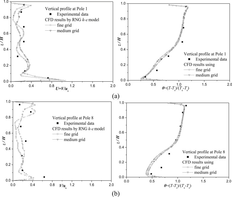
In CFD simulations, medium and fine grid arrangements were utilized with tetrahedral cells of 0.38/1.8 million and a maximum grid size of 10 cm/5 cm at wall surfaces. The heat released from patient, caretaker, equipment and TV was 106 W, 110 W, 36 W, and 24 W, which matched the experiment. The other CFD arrangements are introduced in Subection 3.3. Fig. 5 shows vertical profiles of velocity and temperature at two sample locations (Pole 1 and Pole 8). The height, velocity, and temperature (θ = (T − Ts)/(Te − Ts)) were normalized with respect to the height of the inpatient ward (H = 2.7 m), supply air velocity (u s = 0.14 m/s), temperature at inlet (T s), and main exhaust (T e). Thermal stratification is clearly shown. By using present CFD set-ups with RNG k–ε model, the medium grid performs as well as the fine grid in simulating steady-state turbulent airflows in such a hospital isolation room.
Fig. 5.
Vertical profiles of velocity and temperature in the CFD validation case at (a) Pole 1, (b) Pole 8.
4.3. Steady-state flow and dispersion before door opening (t = 0 s)
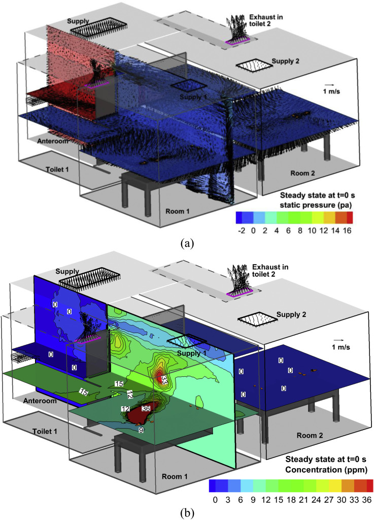
Fig. 6 shows the flow and dispersion in Case [34, 10 s] at the steady-state (t = 0 s) when both doors are closed, including velocity vectors and concentration in the plane of z = 1 m and x = 2.2 m (the center plane of Door 1). Obviously, the flow patterns are mixing ventilation systems in both isolation cubicles. There are strong airflows (about 4 m/s) through Transfer grilles 1 and 2 (Fig. 6a) with total volumetric flow rates of −0.2112 m3/s. Then these airflows reach the vertical wall, go down to the ground (Fig. 6a), flow around the isolation cubicles, enter the toilets contained in each cubicle and finally leave through the ceiling-level exhausts in these two toilets (Fig. 6b). In Room 1, the concentration in the recirculation region was much higher than in other regions (Fig. 6b), and is referred to as the 'highly polluted region'. The concentration in the anteroom and Room 2 was approximately zero, showing that there were few infectious agents spreading out of Room 1.
Fig. 6.
In the steady state (at t = 0 s) of Case [34, 10 s]: (a) Velocity vector and pressure, (b) concentration in x = 2.2 m and z = 1 m.
4.4. An example of transient flow and inter-cubicle dispersion: case [34, 10 s]
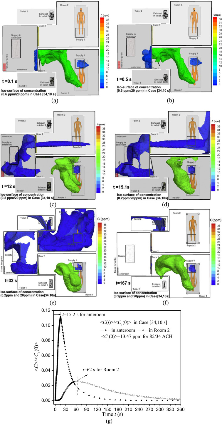
Case [34, 10 s] is presented as an example. Fig. 7 a–f shows iso-surfaces of contaminant concentration at different times. Gaseous contaminants start spreading from Room 1 into the anteroom after Door 1 begins opening (t = 0.1 and 0.5 s, Fig. 7a–b). More agents enter Room 2 from 3 s to 13 s while Door 1 remains fully open (Fig. 7c at 12 s) and from 13 s to 16 s while Door 1 is closing (Fig. 7d at 15.1 s). After Door 1 is closed at t = 16 s, the concentration in Room 2 first rises (Fig. 7e at 32 s), then decreases. For example, at 167 s (Fig. 7f) the concentration in Room 1 approximates its original level and those in the anteroom and in Room 2 become low. To quantify the concentration variation, Fig. 7g shows normalized spatial average concentration <C(t)>/<C 1(0)> in Room 2 and the anteroom for Case [34, 10 s], where <C 1(0)>=13.47 ppm is the spatial average concentration in Room 1 at t = 0 s in this case. The anteroom first experiences a peak of <C > max = 1.52 ppm at t = 15.2 s, and afterward <C> decreases. After Door 1 is closed at t = 16 s, <C> in the anteroom decreases more quickly, while <C> in Room 2 continues increasing until it reaches the maximum concentration of <C>max = 0.35 ppm at t = 62.0 s.
Fig. 7.
Iso-surfaces of concentration at 0.2 ppm and 20 ppm in Case [34, 10 s] at (a) 0.1 s, (b) 0.5 s, (c) 12 s, (d) 15.1 s, (e) 32 s and (f) 167 s. (g) Normalized spatial average concentration <C(t)>/<C1(0)> in Room 2 and anteroom. <C1(0)> is <C(t)> in Room 1 at steady state (t = 0 s) before door opening.
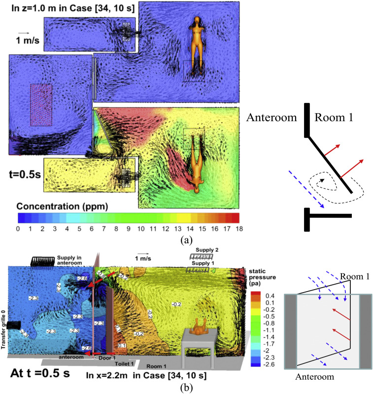
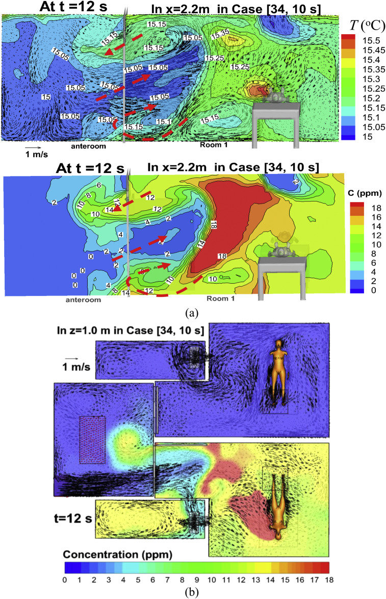
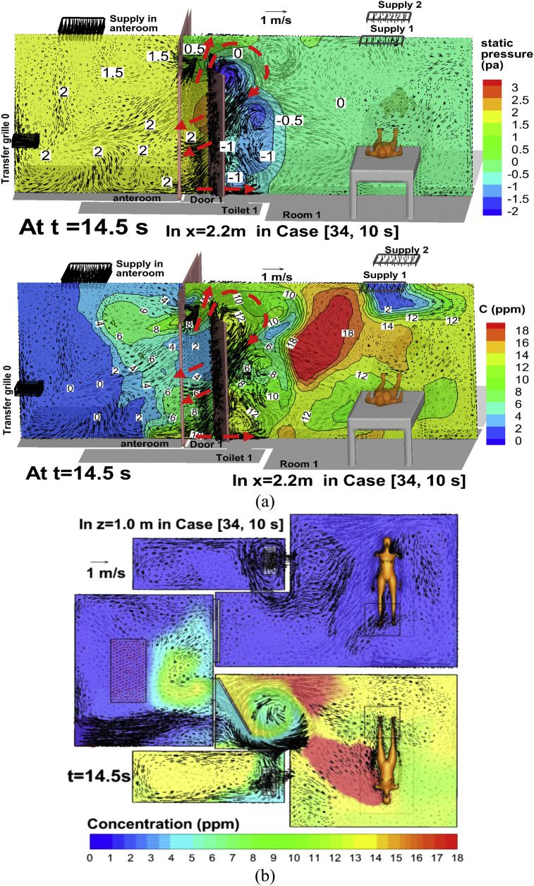
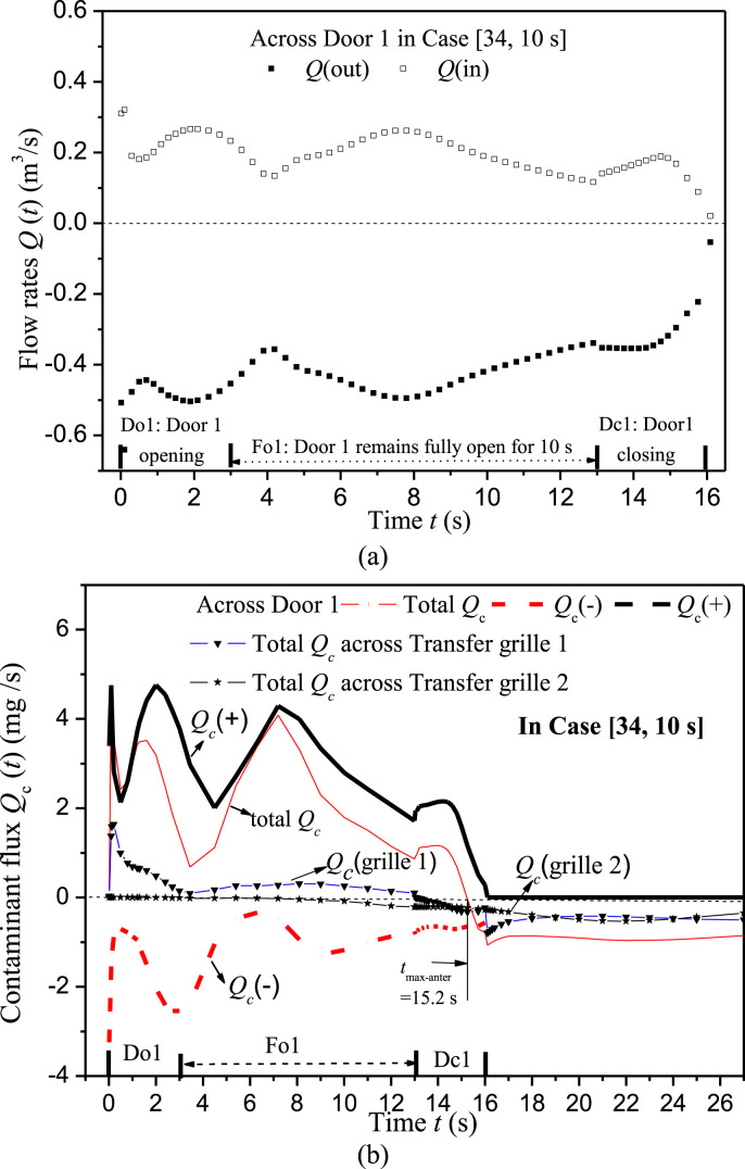
To analyze the transient dispersion processes, Fig. 8, Fig. 9, Fig. 10 display velocity vector, concentration, temperature, and static pressure at certain cross sections at times of 0.5 s, 12 s, 14.5 s in Case [34, 10 s]. Fig. 11 displays the history of flow rates and contaminant fluxes through Door 1 in Case [34, 10 s]. Here we point out that a positive value denotes flow rate and contaminant flux entering the anteroom, and a negative value represents leaving it. The net flow rate through Door 1 and Transfer grille 1 is always −0.2112 m3/s in Case [34, 10 s]. But the net contaminant fluxes transiently vary (Fig. 11b).
Fig. 8.
Static pressure and velocity vector in Case [34, 10 s] at t = 0.5 s: (a) x = 2.2 m, (b) z = 1.0 m.
Fig. 9.
Velocity vector, concentration and/or temperature in Case [34, 10 s] at t = 12 s: (a) x = 2.2 m, (b) z = 1.0 m.
Fig. 10.
Velocity vector, concentration and/or static pressure in Case [34, 10 s] at t = 14.5 s: (a) x = 2.2 m, (b) z = 1.0 m.
Fig. 11.
(a) Flow rates across Door 1 in Case [34, 10 s], (b) Contaminants fluxes through Door 1 and Transfer grilles in Case [34, 10 s]. Note that a positive value denotes flow rate or contaminants entering the anteroom and a negative value means leaving it.
4.4.1. Classification and analysis of four phases
4.4.1.1. Phase 1: Opening motion of Door 1 (0 s < t < 3 s, Fig. 8, Fig. 11)
The opening motion of Door 1 produces two-way airflows and contaminant transport (Fig. 8, Fig. 11). Firstly, we define ‘the swept volume of door motion’ as the space Door 1 passes and moves through. The sweeping motion of Door 1, coupled with the flow from Transfer grille 0 produces a negative flow rate leaving the anteroom and entering Room 1 through the swept volume (Figs. 8a and 11). Secondly, the door motion produces a higher pressure in Room 1 than in the anteroom (Fig. 8b). The pressure is relatively low near the top and bottom of the doorway where considerable positive flow rate (Q(in) in Fig. 11a) is produced, and which is the main reason for contaminant flux entering the anteroom from Room 1 (Q c(+) in Fig. 11b). Vortexes are induced near the tip of Door 1 (Fig. 8a) which are also reported in the literature [7], [8]. In this period Door 2 is always closed, and contaminant flux through Transfer grille 2 (Fig. 11b) is small because little contaminant reaches Transfer grille 2 over such a short duration (3 s).
4.4.1.2. Phase 2: Door 1 remaining fully open (3 s < t < 33 s, Fig. 9, Fig. 11)
Another type of two-way airflow and contaminant exchange was generated (Fig. 9a). The temperature difference between the anteroom and Room 1, combined with airflow from Transfer grille 0 and the entire ventilation system is the main cause of contaminant leakage. Since the net flow rate across the doorway of Door 1 is about −0.2112 m3/s in Case [34, 10 s] and its cross area is 2.444 m2, the average velocity is only −0.08 m/s, which is not sufficient to prevent contaminant leakage out of Room 1 when Door 1 remains fully open (0.2 m/s required by Tung et al. [6]). Contaminants mainly enter the anteroom through the top of Door 1 and Transfer grille 1 (Fig. 11b). Chen et al. [44] reported similar findings in a hospital ward consisting of four cubicles with 'positive pressure' towards their shared corridor. If the door is open, the slightly higher temperature in the corridor compared with the cubicles does induce two-way air exchange and contaminant transport across the doorway from one source cubicle into the corridor, and subsequently into the other 'clean' cubicles. A good technique is to install curtains at the doorway [45] which can reduce the area of the doorway and thus increase this average velocity through it. Over this period (3 s < t < 13 s), as displayed in Fig. 11b, the net contaminant fluxes across the Door 1 doorway is positive (i.e. entering the anteroom and leaving Room 1), meanwhile there is an increasing negative contaminant flux through Transfer grille2 (i.e. leaving the anteroom and entering Room 2).
4.4.1.3. Phase 3: Door 1 closing motion (33 s < t < 36 s, Fig. 10, Fig. 11)
Pressure in the anteroom is relatively higher than in Room 1 (Fig. 10a). The closing motion also induces vortexes behind Door 1 and a two-way airflow pattern (Fig. 10). Fig. 11a–b shows that there is considerable positive flow rate and contaminant flux into the anteroom across the doorway of Door 1 due to the sweeping effect of the closing motion. Meanwhile there is much greater negative flow rate and contaminant flux re-entering Room 1 through the bottom and top of the doorway and Transfer grille 1. Negative contaminant fluxes entering Room 2 through Transfer grille 2 continue to rise (Fig. 11b). As displayed in Fig. 7g, <C(t)> in the anteroom reaches its maximum value at t = 15.2 s. As shown in Fig. 11b, total Qc of the anteroom becomes negative after t = 15.2 s, i.e. the negative contaminant fluxes leaving the anteroom across Door 1 doorway and Transfer grilles 1 and 2 (Qc(−)+Qc(grille 2) +Qc(grille 1)) start to exceed that entering the anteroom across Door 1 doorway (Qc(+)).
4.4.1.4. Phase 4: After Door 1 is fully closed (t > 16 s, Fig. 11)
After Door 1 is closed, the negative pressure design produces the negative constant flow rates (−0.2112 m3/s) through Transfer grilles 1 and 2. Consequently, the two-way air exchange disappears. Contaminants are quickly removed from the anteroom across two transfer grilles (Fig. 11b). Considerable Qc across Transfer grille 2 entering Room 2 can explain why the concentration in Room 2 increases until t = 62 s (Fig. 7g).
Overall, Door 1 remaining fully open for 10 s contributes similarly to inter-cubicle transmission as the opening and closing motion of Door 1 (only 3 s). With a scale physical model, Fontana and Quintino [46] experimentally confirmed that door operation can produce a dirty air transfer in the clean room, and that transfer entity appears strongly related to air volume displaced in the door opening operation but almost independent from differential pressure and flow rate imbalance. However, our simulation results show that the amount of airborne agents transferred into the clean anteroom depend on not only the transient two-way airflow induced by door motion but also the unsteady concentration gradient across the doorway. Thus the transport of airborne agents across the doorway into the clean anteroom and to the neighbor cubicle is a much more complicated and transient process than the scaled model in the literature [46]. Further investigations with various speed of door sweeping motion (for example 3 s, 2 s, 1 s) are still required to check how the speed of door motion influences inter-cubicle transmission in such realistic hospital wards.
4.5. How different door operations affect inter-cubicle transmission
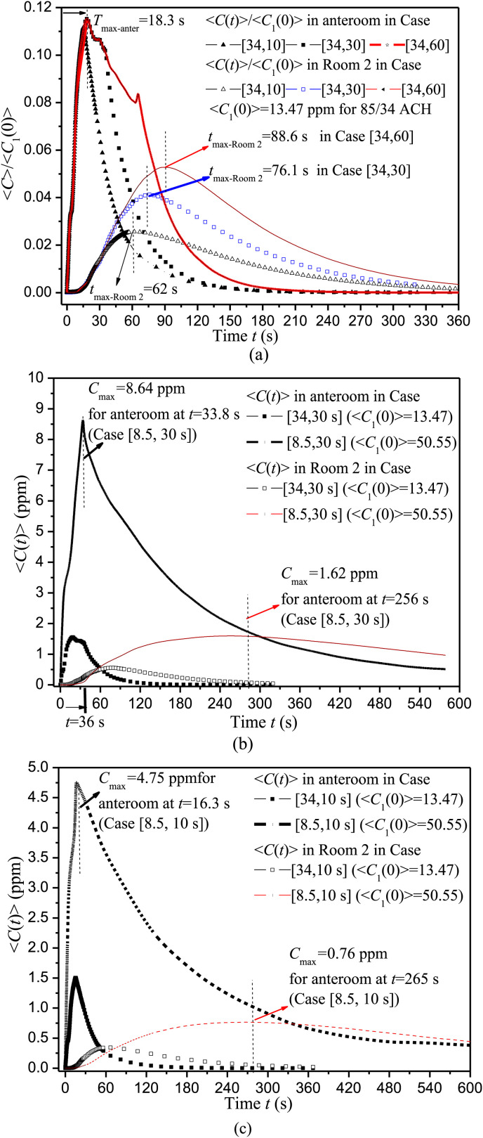
To investigate the impact of the duration of door opening, Fig. 12 a displays <C(t)>/<C>1(0) in Room 2 and the anteroom in Case [34, 10 s], Case [34, 30 s] and Case [34, 60 s]. Table 4 summarizes <C>1(0) in Room 1, the peak concentration <C>max and peak time in the anteroom and Room 2.
Fig. 12.
<C(t)> in Room 2 and anteroom in test cases with different door operations.
Table 4.
Significant parameters for the four test cases investigated.
| Case | <C> max(ppm) and peak time (s) in anteroom | <C> max(ppm) and peak time (s) in Room 2 | <C>1(0) (ppm) | ACH in CFD | ||
|---|---|---|---|---|---|---|
| [34,10 s] | 15.2 s | 1.50 | 62.0 s | 0.35 | 13.47 | 85.0/34.0 |
| [34,30 s] | 18.3 s | 1.55 | 76.1 s | 0.55 | ||
| [34,60 s] | 18.3 s | 1.55 | 88.6 s | 0.71 | ||
| [ 8.5,30 s] | 33.8 s | 8.64 | 256 s | 1.62 | 50.55 | 21.25/8.5 |
| [ 8.5,10 s] | 16.3 s | 4.75 | 265 s | 0.76 | ||
<C>max in Room 2 and peak time are 62.0 s/0.35 ppm, 76.1 s/0.55 ppm and 88.6 s/0.71 ppm if Door 1 remains fully open for 10 s, 30 s and 60 s, with similar <C>max and peak time in the anteroom (15.2 s/1.50 ppm, 18.3 s/1.55 ppm). This shows that, the longer Door 1 remains fully open, the greater the transport of infectious agents into Room 2 through the shared anteroom, but <C>max in the anteroom does not rise, apparently because the net contaminant flux of the anteroom becomes negative at t = 15.2 s or 18.3 s (Fig. 12a).
To study the effect of air change rate, Fig. 12b–c shows <C(t)> in Room 2 and the anteroom in Case [34, 30 s] and Case [8.5, 30 s], Case [34, 10 s] and Case [8.5, 10 s]. As displayed in Table 4, <C>1(0) is 50.55 ppm if 8.5 ACH is used for each cubicle, which is much greater than 13.47 ppm for 34 ACH. In Case [8.5, 10 s] and Case [8.5, 30 s], <C>max in the anteroom is 4.75 ppm at 16.3 s and 8.64 ppm at 33.8 s, that in Room 2 is 0.76 ppm at 265 s and 1.62 ppm at 256.0 s. The comparisons with 34 ACH verify that, if reducing the air change rate of each cubicle from 34 ACH to 8.5 ACH, <C> in Room 1 rises about 3.5 times, <C>max in the anteroom increases about 3–5 times and that in Room 2 increases about 2–3 times. More time is also required to reach the peak concentration in the anteroom and room 2, as well as to remove contaminant leaked into the anteroom and Room 2. Thus the amount of inter-cubicle transmission and exposure time in Room 2 increases greatly if air change rate decreases.
5. Conclusion
Both field experiments and CFD simulations show that, despite the maintenance of negative pressure gradients across the doorway with high air change rates (85ACH for the anteroom and 34 ACH for each isolation cubicle as in a real ward in a Hong Kong hospital), infectious agents in one 'dirty' isolation cubicle (Room 1) with a source manikin can spread into the other 'clean' cubicle (Room 2) through the shared anteroom if the door is open. Throughout the door opening and closing motion, the door sweeping effect in combination with the ventilation system dominates two-way airflow and contaminant exchange. When the dirty cubicle door remains fully open for a while, the average air velocity through the doorway is small and the temperature difference across this doorway is the main cause of two-way contaminant exchange and inter-cubicle transmission.
Our analysis shows that, if 34 ACH is used for each cubicle, the longer the dirty cubicle door remains fully open (10, 30 or 60 s), the more airborne pathogens enter the clean cubicle (Room 2), but the peak concentration in the anteroom only increases slightly. Keeping the door completely open possibly contributes to the major fraction of inter-cubicle transmission when the duration time (30 s, 60 s) is much longer than the door sweeping processes (only 3 s). Air change rate is another important parameter. If the air change rate for each cubicle decreases from 34 ACH to 8.5 ACH, more infectious agents enter the anteroom and the clean cubicle, meanwhile it requires more time to reach their peak concentration and to remove the leaked airborne pathogens once the dirty cubicle door is closed.
Overall, the opening of hinged doors does pose a significant risk of containment failure, and the use of shared anterooms for isolation cubicles poses the risk of inducing inter-cubicle infection. Considering that the negative pressure in isolation cubicles is sufficient to prevent inter-cubicle airborne transmission if wind speed across the doorway is sufficiently high [6], it is recommended that curtains can be installed at doorway locations to reduce the risk of airborne pathogen leakage [45]. Other techniques are also plausible, such as using air cleaners [47], using facemasks [48], etc. Although further investigations are still required with respect to particles and droplets simulations, this paper offers meaningful findings for the inter-cubicle transmission of gaseous agents when a shared anteroom is used.
Acknowledgment
This study was financially supported by the National Natural Science Foundation of China (No. 51278440) and (No. 51478486) as well as the Fundamental Research Funds for the Central Universities of Sun Yat-sen University (No. 2013390003165002). Thanks go to Dr WH Seto and Ms Patricia Ching, Mr Lei Zhang for help with the field measurement. We also thank the hospital engineers, ward managers, and ward nurses for their assistance during this study.
References
- 1.WHO . World Health Organization; Geneva, Switzerland: 2007. International travel and health; p. 74. [Google Scholar]
- 2.Morawska L. Droplet fate in indoor environments, or can we prevent the spread of infection? Indoor Air. 2006;16:335–347. doi: 10.1111/j.1600-0668.2006.00432.x. [DOI] [PubMed] [Google Scholar]
- 3.Centers for Disease Control and Prevention Guidelines for preventing the transmission of Mycobacterium tuberculosis in health care facilities. Morb Mortal Recomm Rep. 2005;54(RR-17):6–7. [PubMed] [Google Scholar]
- 4.Facility Guidelines Institute . Facility Guidelines Institute; Dallas (TX): 2010. Guidelines for design and construction of hospital and health care facilities. [Google Scholar]
- 5.Tang J.W., Li Y., Eames I., Chan P.K., Ridgeway G.L. Factors involved in the aerosol transmission of infection and control of ventilation in healthcare premises. J Hosp Infect. 2006;64:100–114. doi: 10.1016/j.jhin.2006.05.022. [DOI] [PMC free article] [PubMed] [Google Scholar]
- 6.Tung Y., Shih Y., Hu S. Numerical study on the dispersion of airborne contaminants from an isolation room in the case of door opening. Appl Therm Eng. 2009;29:1544–1551. doi: 10.1016/j.applthermaleng.2008.07.009. [DOI] [PMC free article] [PubMed] [Google Scholar]
- 7.Tang J.W., Eames I., Li Y., Taha Y.A., Wilson P., Bellingan G. Door-opening motion can potentially lead to a transient breakdown in negative-pressure isolation conditions: the importance of vorticity and buoyancy airflows. J Hosp Infect. 2005;61:283–296. doi: 10.1016/j.jhin.2005.05.017. [DOI] [PMC free article] [PubMed] [Google Scholar]
- 8.Eames I., Shoaib D., Klettner C.A., Taban V. Movement of airborne contaminants in a hospital isolation room. J R Soc Interface. 2009;6:S757–S766. doi: 10.1098/rsif.2009.0319.focus. [DOI] [PMC free article] [PubMed] [Google Scholar]
- 9.Rydock J.P., Eian P.K. Containment testing of isolation rooms. J Hosp Infect. 2004;57:228–232. doi: 10.1016/j.jhin.2004.01.032. [DOI] [PubMed] [Google Scholar]
- 10.Johnson D.L., Lynch R.A., Mead K.R. Containment effectiveness of expedient patient isolation units. Am J Infect Control. 2009;37:94–100. doi: 10.1016/j.ajic.2008.05.011. [DOI] [PubMed] [Google Scholar]
- 11.Adams N.J., Johnson D.L., Lynch R.A. The effect of pressure differential and care provider movement on airborne infectious isolation room containment effectiveness. Am J Infect Control. 2011;39:91–97. doi: 10.1016/j.ajic.2010.05.025. [DOI] [PubMed] [Google Scholar]
- 12.Choi J.I., Edwards J.R. Large-eddy simulation of human-induced contaminant transport in room compartments. Indoor Air. 2012;22:77–87. doi: 10.1111/j.1600-0668.2011.00741.x. [DOI] [PubMed] [Google Scholar]
- 13.Poussou S.B., Mazumdar S., Plesniak M.W., Sojka P.E., Chen Q.Y. Flow and contaminant transport in an airliner cabin induced by a moving body: model experiments and CFD predictions. Atmos Environ. 2010;44:2830–2839. [Google Scholar]
- 14.Mazumdar S., Poussou S.B., Lin C.H., Isukapalli S.S., Plesniak M.W., Chen Q.Y. Impact of scaling and body movement on contaminant transport in airliner cabins. Atmos Environ. 2011;45:6019–6028. [Google Scholar]
- 15.Shih Y.C., Chiu C.C., Wang O. Dynamic airflow simulation within an isolation room. Build Environ. 2007;42:3194–3209. doi: 10.1016/j.buildenv.2006.08.008. [DOI] [PMC free article] [PubMed] [Google Scholar]
- 16.Mazumdar S., Yin Y., Guity A., Marmion P., Gulick B., Chen Q. Impact of moving objects on contaminant concentration distributions in an inpatient room with displacement ventilation. HVAC&R Res. 2010;16:545–564. [Google Scholar]
- 17.Hang J., Li Y., Jin R. The influence of human walking on the flow and airborne transmission in a six-bed isolation room: tracer gas simulation. Build Environ. 2014;77:119–134. doi: 10.1016/j.buildenv.2014.03.029. [DOI] [PMC free article] [PubMed] [Google Scholar]
- 18.Goldasteh I., Tian Y.L., Ahmadi G., Ferro A.R. Human induced flow field and resultant particle resuspension and transport during gait cycle. Build Environ. 2014;77:101–109. [Google Scholar]
- 19.Wang J., Chow T.T. Numerical investigation of influence of human walking on dispersion and deposition of expiratory droplets in air-borne infection isolation room. Build Environ. 2011;46:1993–2002. [Google Scholar]
- 20.Xie X., Li Y., Sun H., Liu L. Exhaled droplets due to talking and coughing. J R Soc Interface. 2009;6:S703–S714. doi: 10.1098/rsif.2009.0388.focus. [DOI] [PMC free article] [PubMed] [Google Scholar]
- 21.Zhai S., Li Z., Zhao B. State-space analysis of influencing factors on airborne particle concentration in aircraft cabins. Build Environ. 2014;74:13–21. [Google Scholar]
- 22.Nicas M., Nazaroff W.W., Hubbard A. Toward understanding the risk of secondary airborne infection: emission of respirable pathogens. J Occup Environ Hyg. 2005;2:143–154. doi: 10.1080/15459620590918466. [DOI] [PMC free article] [PubMed] [Google Scholar]
- 23.Zhao B., Zhang Y., Li X., Yang X., Huang D. Comparison of indoor aerosol particle concentration and deposition in different ventilated rooms by numerical method. Build Environ. 2004;39:1–8. [Google Scholar]
- 24.Chen C., Zhao B. Some questions on dispersion of human exhaled droplets in ventilation room: answers from numerical investigation. Indoor Air. 2010;20:95–111. doi: 10.1111/j.1600-0668.2009.00626.x. [DOI] [PubMed] [Google Scholar]
- 25.Zhao B., Wu J. Numerical investigation of particle diffusion in a clean room. Indoor Built Environ. 2005;14:469–479. [Google Scholar]
- 26.Zhao B., Zhang Z., Li X.T. Numerical study of the transport of droplets or particles generated by respiratory system indoors. Build Environ. 2005;40:1032–1039. doi: 10.1016/j.buildenv.2004.09.018. [DOI] [PMC free article] [PubMed] [Google Scholar]
- 27.Chao C.Y.H., Wan M.P., Sze To G.N. Transport and removal of expiratory droplets in hospital ward environment. Aero Sci Technol. 2008;42:377–394. [Google Scholar]
- 28.Qian H., Li Y., Nielsen P.V., Hyldgaard C.E., Wong T.W., Chwang A.T.Y. Dispersion of exhaled droplet nuclei in a two-bed hospital ward with three different ventilation systems. Indoor Air. 2006;16:111–128. doi: 10.1111/j.1600-0668.2005.00407.x. [DOI] [PubMed] [Google Scholar]
- 29.Qian H., Li Y., Nielsen P.V., Huang X. Spatial distribution of infection risk of SARS transmission in a hospital ward. Build Environ. 2009;44:1651–1658. [Google Scholar]
- 30.Zhu S.W., Srebric J., Spengler J.D., Demokritou P. An advanced numerical model for the assessment of airborne transmission of influenza in bus microenvironments. Build Environ. 2012;47:67–75. doi: 10.1016/j.buildenv.2011.05.003. [DOI] [PMC free article] [PubMed] [Google Scholar]
- 31.Gilkeson C.A., Camargo-Valero M.A., Pickin L.E., Noakes C.J. Measurement of ventilation and airborne infection risk in large naturally ventilated hospital wards. Build Environ. 2013;65:35–48. [Google Scholar]
- 32.Li Y., Huang X., Yu I.T.S., Wong T.W., Qian H. Role of air distribution in SARS transmission during the largest nosocomial outbreak in Hong Kong. Indoor Air. 2005;15:83–95. doi: 10.1111/j.1600-0668.2004.00317.x. [DOI] [PubMed] [Google Scholar]
- 33.Yin Y.G., Gupta J.K., Zhang X.S., Liu J.J., Chen Q.Y. Distributions of respiratory contaminants from a patient with different postures and exhaling modes in a single-bed inpatient room. Build Environ. 2011;46(1):75–81. doi: 10.1016/j.buildenv.2010.07.003. [DOI] [PMC free article] [PubMed] [Google Scholar]
- 34.Li Y., Leung G.M., Tang J.W., Yang X., Chao C.Y.H., Lin J.Z. Role of ventilation in gaseous transmission of infectious agents in the built environment: a multidisciplinary systematic review. Indoor Air. 2007;17:2–18. doi: 10.1111/j.1600-0668.2006.00445.x. [DOI] [PubMed] [Google Scholar]
- 35.Wang M., Lin C.H., Chen Q.Y. Advanced turbulence models for predicting particle transport in enclosed environments. Build Environ. 2012;47:40–49. [Google Scholar]
- 36.He Q.B., Niu J.L., Gao N.P., Zhu T., Wu J.Z. CFD study of exhaled droplet transmission between occupants under different ventilation strategies in a typical office room. Build Environ. 2011;46(2):397–408. doi: 10.1016/j.buildenv.2010.08.003. [DOI] [PMC free article] [PubMed] [Google Scholar]
- 37.Qian H., Li Y. Removal of exhaled particles by ventilation and deposition in a multibed gaseous infection isolation room. Indoor Air. 2010;20:284–297. doi: 10.1111/j.1600-0668.2010.00653.x. [DOI] [PubMed] [Google Scholar]
- 38.Yin Y., Xu W., Gupta J.K., Guity A., Marmion P., Manning A. Experimental study on displacement and mixing ventilation systems for a patient ward. HVAC&R Res. 2009;15:1175–1191. [Google Scholar]
- 39.FLUENT 6.3 . 2006. User's guide. [Google Scholar]
- 40.Zhang Z., Zhang W., Zhai Z., Chen Q. Evaluation of various turbulence models in predicting airflow and turbulence in enclosed environments by CFD: part-2: comparison with experimental data from literature. HVAC&R Res. 2007;13:871–886. [Google Scholar]
- 41.Brohus H. Aalborg University; Denmark: 1997. Personal exposure to contaminant sources in ventilated rooms. PhD Thesis. [Google Scholar]
- 42.Gupta J.K., Lin C.H., Chen Q. Flow dynamics and characterization of a cough. Indoor Air. 2009;19:517–525. doi: 10.1111/j.1600-0668.2009.00619.x. [DOI] [PubMed] [Google Scholar]
- 43.Gupta J.K., Lin C.-H., Chen Q. Characterizing exhaled airflow from breathing and talking. Indoor Air. 2010;20:31–39. doi: 10.1111/j.1600-0668.2009.00623.x. [DOI] [PubMed] [Google Scholar]
- 44.Chen C., Zhao B., Yang X., Li Y. Role of two-way airflow owing to temperature difference in severe acute respiratory syndrome transmission: revisiting the largest nosocomial severe acute respiratory syndrome outbreak in Hong Kong. J R Soc Interface. 2010;8:699–710. doi: 10.1098/rsif.2010.0486. [DOI] [PMC free article] [PubMed] [Google Scholar]
- 45.Ching W.H., Leung M.K.H., Leung D.Y.C., Li Y., Yuen P.L. Reducing risk of gaseous transmitted infection in hospitals by use of hospital curtains. Indoor Built Environ. 2008;17:252–259. [Google Scholar]
- 46.Fontana L., Quintino A. Experimental analysis of the transport of airborne contaminants between adjacent rooms at different pressure due to the door opening. Build Environ. 2014;81:81–91. [Google Scholar]
- 47.Chen C., Zhao B., Cui W.L., Dong L., An N., Ouyang X.Y. The effectiveness of an air cleaner in controlling droplet/aerosol particle dispersion emitted from a patient's mouth in the indoor environment of dental clinics. J R Soc Interface. 2010;7(48):1105–1118. doi: 10.1098/rsif.2009.0516. [DOI] [PMC free article] [PubMed] [Google Scholar]
- 48.Lai A.C.K., Poon C.K.M., Cheung A.C.T. Effectiveness of facemasks to reduce exposure hazards for airborne infections among general populations. J R Soc Interface. 2012;9(70):938–948. doi: 10.1098/rsif.2011.0537. [DOI] [PMC free article] [PubMed] [Google Scholar]


