Abstract
This study reports a method for humidity sensing based on a specialty microstructured optical fiber (MOF). A suspended tri-core MOF was fabricated using the stack and draw technique. A low finesse sensing head was prepared by depositing a chitosan polymer matrix within the holes of the MOF, forming a Fabry-Pérot interferometer as a sensing platform while the chitosan film acts as the sensing material. The use of the probe for real-time breath monitoring was also successfully demonstrated. The probe possessed a maximum sensitivity of 81.05 pm/(%RH) for 90–95%RH range while the linear region of the sensor ranged from 70–95%RH. The temperature cross correlation was also experimented, and a lower influence of external temperature was observed. The probe shows an ultrafast response during human breath monitoring with a rising time and recovery time of 80 ms and 70 ms, respectively.
Subject terms: Physics, Optics and photonics
Introduction
Humidity is an essential criteria that should be accounted for in industrial, agricultural applications as well as in human activities, for example, manufacturing and storage of electronic and computer components, food storage, air conditioning and in pharmaceutical industry1–6. Apart from having negative impacts on people with dry skin, low humidity also affects individuals who are suffering from eczema7 leading towards increased skin irritations. Furthermore, high humidity may cause discomfort during breathing especially if the person has any chronic lung condition including COPD (Chronic obstructive pulmonary disease) or asthma8. In industrial applications, a specific humidity level is required for fabrication of various devices, or it may result in high energy level consumptions5. Additionally, humidity sensors are also being used by the European Organization for Nuclear Research (CERN) to monitor experiments in relation to high-energy physics (HEP) at specific humidity levels9. Hence, continuous monitoring of air humidity is essential in enhancing human comfort levels as well as in industrial applications.
Over the last few decades, optical fiber technology has significantly evolved and a wide range of physical, chemical and biological sensors have been developed. Many different physical parameters such as displacement, temperature, pressure, refractive index, current, electric field, magnetic field and humidity have been detected using optical fibers either intrinsically or extrinsically owing to their numerous advantages of compactness, immunity to external electromagnetic interference, corrosion resistance, applicability in multiplexing and remote sensing. The detection of relative humidity (RH) using optical fiber as a sensing platform, including evanescent wave sensors10,11, fiber Bragg gratings12,13, modal interferometers14,15 and Fabry-Perot (FP) interferometers16,17 have been reported. Among these, FP interferometers are a commonly used transducing platform to realize RH sensing as these are robust, and small in size. FP cavities are also used in the fabrication of a broad range of sensors to monitor pressure18, humidity16, force19, and strain20. Suspended core microstructured optical fibers (MOFs) consist of large air holes surrounding a small core which is only a few microns. In such fibers, the core of the fiber is suspended by thin silica struts. Several studies have reported employing suspended-core MOFs for the development of temperature sensors21, volatile organic compound (VOC) sensors22, displacement sensors23, curvature/bend sensors24, and humidity sensors25 due to their intrinsic features. The special geometry of these fibers facilitate the advantage of strong interaction between the evanescent field and the receptors attached within the holes22.
Generally, the working principle of an RH sensor is based on the change in volume and refractive index of the hygroscopic material as they undergo changes in the RH values of the surrounding. Hence, the performance of RH sensors is strongly dependent on the properties of these hygroscopic materials such as polyimide13, SiO216, SnO225, polyvinyl alcohol14, agarose10, gelatin11 and chitosan17,26. Among them chitosan based hydrogels have shown great potential in humidity sensing due to its high degree of swelling27, reversibility, easy preparation, non-toxicity, and broad range of transparency in light spectrum (300–2700 nm)28.
Based on the fiber geometry and types of hygroscopic materials used, a number of studies have reported optical fiber based humidity sensors and a few review articles6,29 have also been published summarizing the extensive use of these sensors. The sensors based on evanescent wave spectroscopy are generally designed through tapering the middle section of fiber and deposition of the hygroscopic medium over the sensing medium layer30. In another paper reported by Mathew et al., buffer-stripped bent SMF together with Polyethylene Oxide (PEO) have been used where PEO acts as the humidity absorbing material31. Similarly, there are several other reports on fiber Bragg grating based humidity sensors32,33. The sensing mechanism of broadly used FBG based humidity sensors basically relies on the hygroscopic property of the fiber core as it changes its own refractive index. Thus, to realize these sensors, POFs (polymer optical fibers) fabricated using PMMA have been used in various studies33. Additionally, a few studies have also reported the use of conventional SMF based on either tilted FBGs or long period gratings34–36. The sensors based on these studies are also highly sensitive, but they suffer from a high response time. When considering interferometric sensors, a broad range of sensors have been reported in literatures based on Mach-Zehnder interferometry, Sagnac interferometry and microfiber resonator37–39. In a study based on Mach-Zehnder Interferometry, a hetro-core fiber has been spliced between two SMFs where a [poly-glutamic acid/poly-lysine] nanostructured layer-by-layer was deposited over the hetro-core fiber to achieve RH sensing39. The sensor operates over the humidity range of 50–92.5% with a power loss of 0.26 dB. The sensor has also shown the possibility of breath monitoring with a response time of ~400 ms.
The present study proposes a versatile RH sensor based on a suspended-core MOF utilizing a chitosan polymer as the receptor. A suspended three-core fiber is used as a platform for preparation of the FP cavity. The air holes of the fiber were filled with the chitosan polymer to execute RH sensing. The sensor probe was tested in a climate chamber with RH value varying from 30% to 95%. Wavelength interrogation method was used by tracking the change in dip wavelength in the interference pattern, which occurs due to the change in volume and refractive index of the chitosan polymer at different RH values. The performance of the sensor was characterized in terms of hysteresis, stability, and sensitivity. Finally, real-time breath monitoring of humans is proposed and validated to demonstrate the industrial applicability of the sensing probe.
Results and Discussion
Sensing mechanism and theoretical modelling
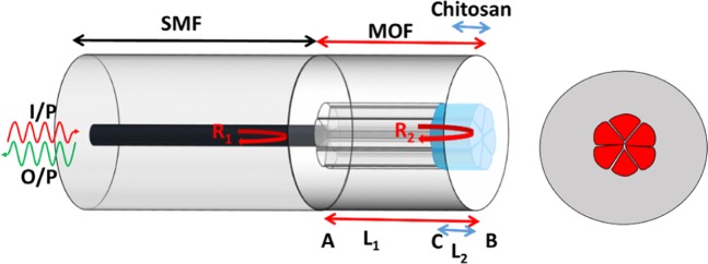
Figure 1 represents the schematic illustration of the fabricated probe consisting of a chitosan polymer filled suspended tri-core fiber as the sensing tip. RH sensing of the probe is based on the interaction of humidity (water vapor) with the hygroscopic chitosan polymer via water adsorption causing a change in refractive index as well as an increased volume of the chitosan polymer. These changes result in a shift in the wavelength as well as the power of the reflected light due to the interaction of the evanescent waves at the core-chitosan interface in the FP cavity. Thus, by monitoring the variation in the wavelength of a specific dip, the ambient humidity surrounding the probe can be determined.
Figure 1.
Schematic illustration of the humidity sensor based on a suspended tri-core MOF using a Fabry-Pérot interferometric configuration, and the cross section of the fiber.
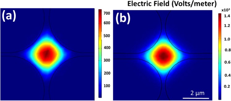
Figure 2(a,b) represent the central element of the fundamental mode (LP01) of the MOF with the absence of any chitosan filling and with chitosan filling in the air holes, respectively, which were simulated by the finite element method (FEM) using COMSOL at 1440.6 nm wavelength. The figures depict that in the presence of chitosan in the air holes, the light guided through the fiber core interacts with the chitosan region by the evanescent field which plays an important role in humidity sensing. The refractive index of the chitosan was considered as 1.4317.
Figure 2.
The central element of the fundamental mode of the MOF with (a) unfilled and (b) filled air holes with chitosan.
The MOF with and without the chitosan polymer filling belongs to a single fiber optic cavity but with different effective indices, since the fundamental mode of light will propagate only through the central core with the absence of any reflective surface in the fiber core. Hence, in theoretical analysis of the effect of the chitosan polymer, the effective refractive index of the bare MOF region is considered as nmof while the effective refractive index of the chitosan filled regime is ɳc. If the fiber optic cavity possesses a length of L1, while the length of the chitosan filled region is L2, then the effective index of the cavity can be calculated as:
| 1 |
Moreover, if the effective refractive index of the SMF region and outer medium are nsmf and nout, respectively then, according to Fresnel’s equation, the reflected intensities at SMF-MOF region and MOF-outer region which are R1 and R2, respectively can be denoted as:
| 2 |
and the phase delay in light due to the fiber optic cavity can be expressed as:
| 3 |
If α represents the intensity attenuation factors and γ,the optical transmission loss factor for the FP cavity then, by taking into account the Eqs. (2) and (3), the normalized reflected intensity can be expressed as17:
| 4 |
Hence, by calculating the effective refractive index of the chitosan filled regime and its change with humidity, the shift in the interference pattern can be observed using Eq. (4).
Additionally, it should be noted that the reduced dimensions of the three fiber cores and the high numerical aperture that exists owing to the difference in the effective refractive index between the fiber core and the air cladding results in an increased evanescent field40,41. Furthermore, the three cores provide sufficient surface area for the deposition of the chitosan material as well.
Humidity sensing response
Figure 3(a) shows the experimental setup used to monitor the sensing performance of the probe towards humidity. The sensing probe was fixed inside a programmable humidity chamber and the humidity was varied from 30% to 95% at a constant temperature of 30 ± 1.5 °C. The set values and the actual values of humidity measured by the inbuilt hygrometer within the chamber, are shown in Fig. 3(b). Subsequently, light was launched into the probe via a broadband source (1420 nm-1600 nm) and an optical circulator while the reflected spectra were recorded by an optical spectrum analyzer (OSA). The resolution of OSA used during the experiment is kept at 0.02 nm.
Figure 3.
(a) Experimental setup for the humidity sensing experiments and (b) calibration curves of humidity and temperature in the climate chamber during the experiments.
Figure 4 shows the measured output spectra of the probe at different humidity values in the climate chamber. A shift in the interference pattern can be observed from Fig. 4, which occurs due to the change in refractive index of the chitosan polymer matrix as the humidity of the climate chamber varies.
Figure 4.
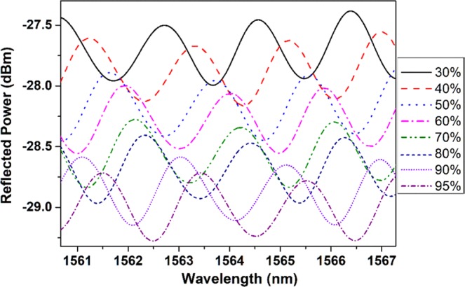
Measured output spectra of the probe at different humidity values in the climate chamber.
Characterization of the humidity sensor
Probe calibration
The sensor probe was calibrated by tracing a specific dip wavelength (1661.5 nm) of the interference pattern. The results are shown in Fig. 5 which indicates a total shift of 2.8 nm for a humidity level varying from 30% to 95%. Furthermore, the hysteresis behavior of the same probe was investigated by repeating the measurement for five times with increasing and decreasing humidity, inside the climate chamber. The standard deviation of the wavelengths at different humidity values was 40 pm, which is represented as error bars in Fig. 5. The maximum sensitivity of the probe was 81.05 pm/(%RH) over a range of 90–95%RH. From Fig. 5, it can be observed that the probe possesses a non-linear behavior due to the presence of the chitosan polymer and also has a non-linear hygroscopic response28. At low RH values, the chitosan polymeric film is nearly at a dehydration state resulting in a less sensitivity whereas at high RH values, the chitosan starts to absorb more moisture causing a larger change in the refractive index as well as the thickness of the chitosan film making the probe more sensitive. The inset in Fig. 5 represents that the probe exhibits a liner response with a humidity change from 70% to 95%, showing a sensitivity of 68.55 pm/(%RH) which verifies the applicability of the probe in high humidity conditions.
Figure 5.
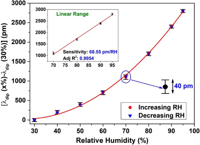
Measured wavelength shift of a specific dip as a function of relative humidity of the environment. The inset shows the linear response of the sensing probe.
Temperature dependence
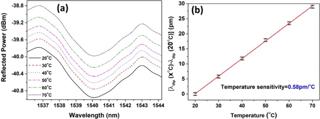
In addition to the humidity characteristics, the behavior of the probe was also investigated with varying ambient temperature from 20 °C to 70 °C at a constant humidity of 50%. The response of the probe for the aforementioned temperature range is shown in Fig. 6(a) and the temperature calibration measurement is shown in Fig. 6(b). It can be clearly observed that the probe has a temperature sensitivity of only 0.58 pm/°C, which is considerably less when compared to its sensitivity towards humidity. The total shift obtained for the temperature range of 20 °C to 70 °C is ~29 pm which exhibits an error of less than 0.5%RH. Therefore, the temperature effect of the proposed humidity sensor can be ignored in the operation range of 20 °C to 70 °C. The change in reflected power is due to the fluctuations in the input light during the experiments, which is also noticeable in the characteristic curve of the sensing probe (Fig. 4).
Figure 6.
(a) Spectral response and the (b) temperature sensitivity of the probe at different temperatures at 50%RH.
Stability of the sensor
The long-term stability of the fabricated probe was explored by exposing the probe to different humidity conditions (i.e. 30%, 50% and 80%) for two days. The variation in the dip wavelengths at different humidity values are plotted as a function of time in Fig. 7, which confirms a strong long-term stability of the sensing probe. The fluctuations in the dip wavelengths for each humidity value is within a measurement error value of 40 pm (about 0.5%RH) which is similar to that observed during the probe calibration process.
Figure 7.
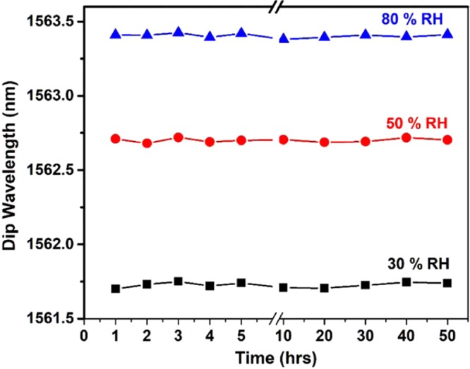
Stability of the humidity sensor measured at 30%, 50% and 80%RH over 2 days.
Breath Measurements
To demonstrate the capabilities and potential application of the sensor, it was tested with real-time monitoring of human breath. Figure 8 illustrates the experimental setup to monitor the breath. The probe was fixed on a solid substrate with an adhesive polyimide tape and the output end of the probe was connected to an optical interrogator (Micro Optics: si255) which can detect the change of the dip wavelength as a function of time.
Figure 8.
Experimental setup for human breath monitoring.
The sampling rate of the interrogator is 5 kHz and the data were collected through a laptop to record the output dip wavelength. During the test, the sensing head was placed in close proximity to the mouth of a person and a variation in the surrounding humidity was observed due to the continuous exhalation.
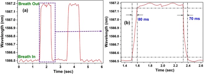
Figure 9(a) shows the wavelength change of one dip during two cycles of breath, including exhalation and inhalation. From the result, it can be clearly seen that the dip wavelength increases during exhalation, and it decreases to the baseline during inhalation. Furthermore, from the result of one cycle of exhalation as shown in Fig. 9(b), it can be observed that the response and recovery time of the sensor are ~80 ms and ~70 ms, respectively.
Figure 9.
(a) Response of the sensor to human breath containing two cycles of exhalation and inhalation and (b) detailed analysis of human breath for one cycle.
Comparison with other studies
Table 1 shows a comparison of the performance of the proposed probe with respect to previously reported research studies for humidity sensing. A fiber optic Sagnac interferometer has also been proposed by Chen et al. using chitosan as the hydroscopic material38 where the sensor possessed a sensitivity of 81 pm/%RH which is relatively close to our proposed sensor. However, the study does not demonstrate any real time experiment. It is evident that the proposed sensor possesses the quickest response time along with a moderate sensitivity, demonstrating its industrial applicability for real time breath monitoring. Liu et al., has reported a Fabry-Perot humidity sensor using chitosan as a water-absorbing receptor to achieve humidity sensing. Even though, the sensitivity of this sensor is better than the proposed sensor, it suffers from a high response time (around 60 seconds) and the study does not demonstrate any industrial application. Although, chitosan has been integrated with optical fibers to realize humidity sensing17,26,38, as demonstrated in our current research study, a combination of micro-structured fiber with chitosan is useful in providing a fast and moderately sensitive response, in real-time breath monitoring which highlights its advantages as a potential candidate for breath monitoring.
T.able 1.
Performance comparison of the proposed sensor and other optical fiber-based humidity sensors reported in literature.
| Sensing Material | Optical fiber | Sensing method | Range (%RH) | Sensitivity (Resolution) | Response time | Application |
|---|---|---|---|---|---|---|
| Gelatin11 | Tapered optical fiber | Interferometric | 9–94 | 0.016 dBm/%RH | 70 ms | |
| TiO2/SnO212 | Long Period Grating | Long Period Grating | 40–95 | 221 pm/%RH | — | |
| Silica/di-ureas32 | Fiber Bragg grating | Fiber Bragg grating | 5–95 | 22.2 pm/%RH | Civil Engineered Structure Monitoring | |
| PMMA polymer33 | Fiber Bragg grating | Etched Polymer Optical Fiber | 30–90 | 33.6 pm/%RH | 7 min | |
| Polyvinyl Alcohal35 | Long Period Grating | Long Period Grating | 33–97 | ~5680 pm/%RH | <1 min | Structural Health Monitoring |
| Polyvinyl Alcohol43 | Tilted Fiber Bragg Grating | Tilted Fiber Bragg Grating | 20–98 | 14.95 dBm/%RH | — | |
| Calcium Chloride34 | Air gap Long Period Grating | Air gap long period grating | 50–95 | 1350 pm/%RH | ||
| SiO2 –Nanospheres36 | Long Period Grating | Long Period Grating |
20–50 50–80 |
63.33 pm/%RH 451.78 pm/%RH |
30 ms (rise) 153 ms (recovery) |
|
| [PDDA/Poly R-478] nanostructured30 | Tapered Fiber | Evanescent wave | 75–100 | 16 dBm/%RH | 300 ms | |
| Polyethylene Oxide (PEO)31 | Buffer-striped 1060XP Fiber | Evanescent wave | 80–95 | 1 dB/%RH | 760 ms | Breath Monitoring |
| No coating37 | Silica/polymer Microfiber |
Knot Resonator |
17–98 |
8.8 pm/%RH (0.017%) |
||
| [poly-glutamic acid/poly-lysine]39 |
Hetro-core Fiber |
Modal Interferometric | 50–92.9 | 0.0052 dB/%RH | 400 ms | Breath Monitoring |
| Polyvinyl Alcohol14 | Photonic Crystal Fiber | Modal Interferometric | 20–95 | 40.9 pm/%RH | — | |
| (P4VP·HCl/PVS)1015 | Thin Core Fiber | Modal Interferometric | 20–90 |
84.3 pm/%RH (0.78%) |
2 sec (rise) 10 sec (fall) |
|
| Chitosan38 | Polarization Maintaining Fiber | Sagnac Interferometer | 20–95 |
81 pm/%RH (2.04%) |
||
| Ti3O5/SiO216 | Single Mode Fiber | Fabry-Perot Interferometer | 1.8–74.7 | 430 pm/%RH | 5 sec | |
| Chitosan26 | Hollow-Core PCF | Fabry-Perot Interferometer | 20–95 | 130 pm/%RH | 380 ms | |
| (PAH/PSS)1544 | Hollow-Core PCF | Fabry-Perot Interferometer | 5–90 |
0.08 dB/%RH (0.125%) |
2 sec (rise) 6 sec (fall) |
|
| Chitosan17 | Hollow-Core PCF | Fabry-Perot Interferometer | 35–95 |
280 pm/%RH (0.02%) |
<60 sec | |
| SnO225 | Twin Suspended Core Fiber | Fabry-Perot Interferometer | 20–90 | 0.14 rad/%RH |
370 ms (rise) 380 ms (recovery) |
Breath Monitoring |
|
Chitosan (Present Study) |
Suspended tri-core Fiber | Fabry-Perot Interferometer | 30–95 |
81.05 pm/%RH (0.5%) |
80 ms (rise) 70 ms (recovery) |
Breath Monitoring |
Conclusion
In conclusion, a Fabry-Perot interferometer based on a homemade suspended tri-core fiber was successfully employed for humidity sensing using the hygroscopic property of chitosan polymeric matrix. The sensor relies on the change in the refractive index of the chitosan polymer which in turn causes a phase change in the reflected light at different surfaces that can be observed by a shift in the interference pattern. In the current study, a shift of 28 pm was observed over a climate humidity level ranging from 30–95%. The probe possessed a linear response over the humidity range from 70–95%. The sensor exhibits a maximum sensitivity of 81.05 pm/(%RH) (for the high humidity ranges from 90–95%) and a maximum deviation of 40 pm, showing an error of only ±0.5%RH. Further performance characteristics of the sensor in terms of hysteresis, stability and influence of the temperature were also analyzed. In an effort to demonstrate the applicability of the proposed sensor in the biomedical industry, the probe was used to monitor human breath where it indicated an extremely fast response without any drift in the baseline. Therefore, such a sensor is promising in biomedical applications such as monitoring breath of individuals suffering from asthma and any lung disease in addition to monitoring humidity levels in agriculture and food storage units where maintaining a certain humidity level is of utmost importance.
Methods
Characterization of the suspended-core MOF
The suspended-core MOF consisting of three cores which are suspended by thin silica struts and surrounded by six large air holes was designed and fabricated using the stack and draw technique42. Figure 10 shows the cross-sectional SEM images of the MOF, where the cores of the fiber are ~1.5 µm in diameter and separated by about 2 µm from each other. The thickness of the silica struts was ~700 nm. The MOF possesses several unique advantages due to its special structure. For example, the large air holes make it easier to deposit various gas sensitive/chemically sensitive materials on the core region, providing strong interaction between the materials and the light guided in the core. Additionally, the reduced diameter of the fiber core and large air holes lead to a stronger evanescent field as discussed in literature41.
Figure 10.
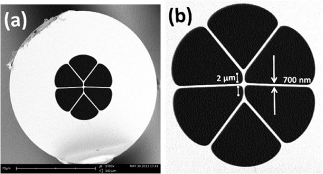
Scanning Electron Microscopic (SEM) images of the cross section of the MOF at (a) 1700X and (b) 4000X magnification.
Fabrication of the sensor
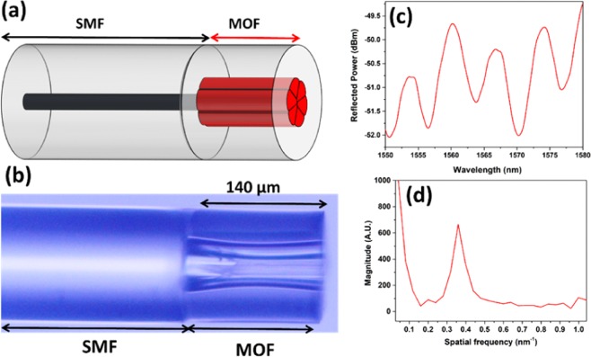
The proposed FPI sensor for humidity sensing was prepared by splicing a conventional single mode fiber (SMF-28) with a suspended three-core MOF. The schematic representation and the microscopic image of this structure are shown in Fig. 11(a,b), respectively. The end of the fiber was perfectly cleaved. Afterwards, a Fitel 175 splicer was used to splice SMF and MOF using a customized splicing program since MOF exhibits large air holes and very thin silica struts. The corresponding interference pattern and the FFT spectrum are shown in Fig. 11(c,d), respectively. The length of the suspended core MOF was maintained at 140 µm.
Figure 11.
(a) Schematic figure and (b) microscopic image of the SMF-MOF probe. (c) Reflected interference pattern and (d) corresponding FFT spectrum of the SMF-MOF probe.
A humidity sensitive chitosan polymer was synthesized and part of the air holes of the MOF was filled with the polymeric solution to create a thin film at the sensing surface. The polymer was synthesized by mixing 1 wt% chitosan powder, (90–95% deacetylation degree and 50–800 mPa·s viscosity) in acetic acid solution (4% v/v) using a magnetic stirrer for 24 h at room temperature (25 °C). Then, the solution was filtered through a filter paper having a 50 µm mesh size. Finally, the tip of the SMF-MOF fiber was dipped vertically in the solution for 30 seconds and then the probe was dried at room temperature for 24 h. This completed the probe fabrication process. The schematic diagram of the final probe is shown in Fig. 1. Measurement of the exact length of the chitosan filled region is rather challenging. However, the approximate length of the chitosan filled regime (1) can be calculated by the capillary action relation:
| 5 |
where, denotes the surface-tension at chitosan-matrix and air interface, is the contact angle, and represents the chitosan polymer density and gravitational velocity, respectively while r is the radius of the air-hole (around 35 µm).
Acknowledgements
The authors would like to acknowledge the financial support from The Hong Kong Polytechnic University (1-ZVGB, 1-BBYE, 1-BBYS), Hong Kong RGC GRF (Grant No. 15210019), and National Natural Science Foundation of China (NSFC) (61905096, 61827820).
Author contributions
A.M.S. conceptualized the study, performed the experiments, analyzed the data and wrote the manuscript. D.S.G. and Z.L. analyzed the data and wrote the manuscript. H.Y.T. analyzed the data, wrote the manuscript and supervised the project.
Competing interests
The authors declare no competing interests.
Footnotes
Publisher’s note Springer Nature remains neutral with regard to jurisdictional claims in published maps and institutional affiliations.
Contributor Information
Dinusha S. Gunawardena, Email: dinusha.gunawardena@polyu.edu.hk
Zhengyong Liu, Email: liuzhengy@mail.sysu.edu.cn.
References
- 1.Blanco M, Coello J, Iturriaga H, Maspoch S, Rovira E. Determination of water in ferrous lactate by near infrared reflectance spectroscopy with a fibre-optic probe. J. Pharm. Biomed. Anal. 1997;16:255–262. doi: 10.1016/S0731-7085(97)00049-6. [DOI] [PubMed] [Google Scholar]
- 2.Kastner W, Neugschwandtner G, Soucek S, Newman HM. Communication systems for building automation and control. Proc. IEEE. 2005;93:1178–1203. doi: 10.1109/JPROC.2005.849726. [DOI] [Google Scholar]
- 3.Dijkink BH, Tomassen MM, Willemsen JHA, Van Doorn WG. Humidity control during bell pepper storage, using a hollow fiber membrane contactor system. Postharvest Biol. Technol. 2004;32:311–320. doi: 10.1016/j.postharvbio.2003.12.002. [DOI] [Google Scholar]
- 4.Sims DA, Gamon JA. Estimation of vegetation water content and photosynthetic tissue area from spectral reflectance: A comparison of indices based on liquid water and chlorophyll absorption features. Remote Sens. Environ. 2003;84:526–537. doi: 10.1016/S0034-4257(02)00151-7. [DOI] [Google Scholar]
- 5.Lo Presti D, Massaroni C, Schena E. Optical Fiber Gratings for Humidity Measurements: A Review. IEEE Sens. J. 2018;18:9065–9074. doi: 10.1109/JSEN.2018.2870585. [DOI] [Google Scholar]
- 6.Ascorbe J, Corres JM, Arregui FJ, Matias IR. Recent developments in fiber optics humidity sensors. Sensors (Switzerland) 2017;17:1–23. doi: 10.3390/s17040893. [DOI] [PMC free article] [PubMed] [Google Scholar]
- 7.Silverberg JI, Hanifin J, Simpson EL. Climatic factors are associated with childhood eczema prevalence in US. J Invest Dermatol. 2014;133:1752–1759. doi: 10.1038/jid.2013.19. [DOI] [PMC free article] [PubMed] [Google Scholar]
- 8.Hansel NN, McCormack MC, Kim V. The Effects of Air Pollution and Temperature on COPD Nadia. COPD J. Chronic Obstr. Pulm. Dis. 2016;13:372–379. doi: 10.3109/15412555.2015.1089846. [DOI] [PMC free article] [PubMed] [Google Scholar]
- 9.Consales M, et al. Fiber optic humidity sensors for high-energy physics applications at CERN. Sensors Actuators, B Chem. 2011;159:66–74. doi: 10.1016/j.snb.2011.06.042. [DOI] [Google Scholar]
- 10.Batumalay M, et al. Study of a fiber optic humidity sensor based on agarose gel. J. Mod. Opt. 2014;61:244–248. doi: 10.1080/09500340.2013.879937. [DOI] [Google Scholar]
- 11.Zhang L, Gu F, Lou J, Yin X, Tong L. Fast detection of humidity with a subwavelength-diameter fiber taper coated with gelatin film. Opt. Express. 2008;16:13349. doi: 10.1364/OE.16.013349. [DOI] [PubMed] [Google Scholar]
- 12.Chen H, Gu Z, Gao K. Humidity sensor based on cascaded chirped long-period fiber gratings coated with TiO2/SnO2 composite films. Sensors Actuators, B Chem. 2014;196:18–22. doi: 10.1016/j.snb.2014.01.090. [DOI] [Google Scholar]
- 13.Kronenberg P, Rastogi PK, Giaccari P, Limberger HG. Relative humidity sensor with optical fiber Bragg gratings. Opt. Lett. 2002;27:1385. doi: 10.1364/OL.27.001385. [DOI] [PubMed] [Google Scholar]
- 14.Li T, et al. Humidity sensor with a PVA-coated photonic crystal fiber interferometer. IEEE Sens. J. 2013;13:2214–2216. doi: 10.1109/JSEN.2012.2234100. [DOI] [Google Scholar]
- 15.Gu B, Yin M, Zhang AP, Qian J, He S. Optical fiber relative humidity sensor based on FBG incorporated thin-core fiber modal interferometer. Opt. Express. 2011;19:4140. doi: 10.1364/OE.19.004140. [DOI] [PubMed] [Google Scholar]
- 16.Xie W, et al. Optical fiber relative-humidity sensor with evaporated dielectric coatings on fiber end-face. Opt. Fiber Technol. 2014;20:314–319. doi: 10.1016/j.yofte.2014.03.008. [DOI] [Google Scholar]
- 17.Liu X, Jiang M, Sui Q, Geng X. Optical fibre Fabry–Perot relative humidity sensor based on HCPCF and chitosan film. J. Mod. Opt. 2016;63:1668–1674. doi: 10.1080/09500340.2016.1167974. [DOI] [Google Scholar]
- 18.Liang, H. et al. Diaphragm-free fiber-optic fabry-perot interferometric gas pressure sensor for high temperature application. Sensors (Switzerland), 18 (2018). [DOI] [PMC free article] [PubMed]
- 19.Dash JN, Liu Z, Gunawardena DS, Tam H-Y. Fabry–Perot cavity-based contact force sensor with high precision and a broad operational range. Opt. Lett. 2019;44:3546. doi: 10.1364/OL.44.003546. [DOI] [PubMed] [Google Scholar]
- 20.Tian J, et al. A Fabry-Perot Interferometer Strain Sensor Based on Concave-Core Photonic Crystal Fiber. J. Light. Technol. 2018;36:1952–1958. doi: 10.1109/JLT.2018.2797104. [DOI] [Google Scholar]
- 21.Martynkien T, Szpulak M, Urbanczyk W. Modeling and measurement of temperature sensitivity in birefringent photonic crystal holey fibers. Appl. Opt. 2005;44:7780. doi: 10.1364/AO.44.007780. [DOI] [PubMed] [Google Scholar]
- 22.Lopez-Torres, D. et al. Comparison between different structures of suspended-core microstructured optical fibers for volatiles sensing. Sensors (Switzerland)18 (2018). [DOI] [PMC free article] [PubMed]
- 23.Villatoro J, Finazzi V, Minkovich VP, Pruneri V, Badenes G. Temperature-insensitive photonic crystal fiber interferometer for absolute strain sensing. Appl. Phys. Lett. 2007;91:1–4. doi: 10.1063/1.2775326. [DOI] [Google Scholar]
- 24.MacPherson WN, et al. Remotely addressed optical fibre curvature sensor using multicore photonic crystal fibre. Opt. Commun. 2001;193:97–104. doi: 10.1016/S0030-4018(01)01260-3. [DOI] [Google Scholar]
- 25.Lopez Aldaba A, et al. SnO2-MOF-Fabry-Perot optical sensor for relative humidity measurements. Sensors Actuators, B Chem. 2018;257:189–199. doi: 10.1016/j.snb.2017.10.149. [DOI] [Google Scholar]
- 26.Chen LH, et al. Chitosan based fiber-optic Fabry-Perot humidity sensor. Sensors Actuators, B Chem. 2012;169:167–172. doi: 10.1016/j.snb.2012.04.052. [DOI] [Google Scholar]
- 27.Murray CA, Dutcher JR. Effect of changes in relative and temperature on ultrathin chitosan films. Biomacromolecules. 2006;7:3460–3465. doi: 10.1021/bm060416q. [DOI] [PubMed] [Google Scholar]
- 28.Mathew J, Thomas KJ, Nampoori VPN, Radhakrishnan P. A Comparative Study of Fiber Optic Humidity Sensors Based on Chitosan and Agarose. Sensors and Transducers. 2007;84:1633–1640. [Google Scholar]
- 29.Alwis L, Sun T, Grattan KTV. Optical fibre-based sensor technology for humidity and moisture measurement: Review of recent progress. Measurement. 2013;46(10):4052–4074. doi: 10.1016/j.measurement.2013.07.030. [DOI] [Google Scholar]
- 30.Corres JM, Arregui FJ, Matías IR. Sensitivity optimization of tapered optical fiber humidity sensors by means of tuning the thickness of nanostructured sensitive coatings. Sens. Act B. 2007;122(2):442–449. doi: 10.1016/j.snb.2006.06.008. [DOI] [Google Scholar]
- 31.Mathew J, Semenova Y, Rajan G, Wang P, Farrell G. Improving the sensitivity of a humidity sensor based on fiber bend coated with a hygroscopic coating. Opt. Las. Tech. 2011;43(7):1301–1305. doi: 10.1016/j.optlastec.2011.03.028. [DOI] [Google Scholar]
- 32.Correia SF, et al. Optical fiber relative humidity sensor based on a FBG with a di-ureasil coating. Sensors. 2012;12(7):8847–8860. doi: 10.3390/s120708847. [DOI] [PMC free article] [PubMed] [Google Scholar]
- 33.Zhang W, Webb DJ, Peng GD. Investigation into time response of polymer fiber Bragg grating based humidity sensors. J. Light. Technol. 2011;30(8):1090–1096. doi: 10.1109/JLT.2011.2169941. [DOI] [Google Scholar]
- 34.Fu MY, Lin GR, Liu WF, Wu C. Fiber-optic humidity sensor based on an air-gap long period fiber grating. Opt. Rev. 2011;18(1):93–95. doi: 10.1007/s10043-011-0038-7. [DOI] [Google Scholar]
- 35.Venugopalan T, Sun T, Grattan KTV. Long period grating-based humidity sensor for potential structural health monitoring. Sens. Act. B. 2008;148(1):57–62. doi: 10.1016/j.sna.2008.07.015. [DOI] [Google Scholar]
- 36.Viegas D, et al. Simultaneous measurement of humidity and temperature based on an SiO2 nanospheres film deposited on a long-period grating in-line with a fiber bragg grating. IEEE Sensors J. 2010;11(1):162–166. doi: 10.1109/JSEN.2010.2055237. [DOI] [Google Scholar]
- 37.Chen LH, et al. Chitosan-coated polarization maintaining fiber-based Sagnac interferometer for relative humidity measurement. IEEE J. Select. Top. Quntm. Electron. 2012;18(5):1597–1604. doi: 10.1109/JSTQE.2012.2194729. [DOI] [Google Scholar]
- 38.Wu Y, Zhang T, Rao Y, Gong Y. Miniature interferometric humidity sensors based on silica/polymer microfiber knot resonators. Sens. Actuators B. 2010;155(1):258–263. doi: 10.1016/j.snb.2010.12.030. [DOI] [Google Scholar]
- 39.Akita S, Sasaki H, Watanabe K, Seki A. A humidity sensor based on a hetero-core optical fiber. Sens. Actuators B. 2010;147(2):385–391. doi: 10.1016/j.snb.2010.03.049. [DOI] [Google Scholar]
- 40.Gupta BD, Singh CD. Fiber-optic evanescent field absorption sensor: A theoretical evaluation. Fiber Integr. Opt. 1994;13:433–443. doi: 10.1080/01468039408202251. [DOI] [Google Scholar]
- 41.Khijwania SK, Gupta BD. Fiber optic evanescent field absorption sensor: effect of fiber parameters and geometry of the probe. Opt. Quntm. Electron. 1999;31(8):625–636. doi: 10.1023/A:1006956824722. [DOI] [Google Scholar]
- 42.Liu Z, Zhang ZF, Tam H-Y, Tao X. Multifunctional smart optical fibers: materials, fabrication, and sensing applications. Photonics. 2019;6:48. doi: 10.3390/photonics6020048. [DOI] [Google Scholar]
- 43.Miao Y-P, Liu B, Liu J, Sun H, Zhao Q-D. Tilted fiber Bragg grating used for relative humidity sensor. Guangdianzi Jiguang/Journal Optoelectron. Laser. 2010;21:978–982. [Google Scholar]
- 44.Sui Q, Jiang M, Jin Z. Optical fiber relative humidity sensor based on Fabry-Perot interferometer coated with sodium-p-styrenesulfonate/allyamine hydrochloride films. Sensors Mater. 2014;26:291. [Google Scholar]


