Abstract
Posterior atlantoaxial fusion is an important surgical technique frequently used to treat various pathologies involving the cervical 1–2 joint. Since the beginning of the 20th century, various fusion techniques have been developed with improved safety profile, higher fusion rates, and superior clinical outcome. Despite the advancement of technology and surgical techniques, posterior C1–2 fusion is still a technically challenging procedure given the complex bony and neurovascular anatomy in the craniovertebral junction (CVJ). In addition, vascular anomalies in this region are not uncommon and can lead to devastating neurovascular complications if unrecognized. Thus, it is important for spine surgeons to be familiar with various posterior atlantoaxial fusion techniques along with a thorough knowledge of various vascular anomalies in the CVJ. Intimate knowledge of the various surgical techniques in combination with an appreciation for anatomical variances, allows the surgeon develop a customized surgical plan tailored to each patient’s particular pathology and individual anatomy. In this article, we aim to provide a comprehensive review of existing posterior C1–2 fusion techniques along with a review of common vascular anomalies in the CVJ.
Keywords: Atlantoaxial fusion, posterior cervical fusion, screw fixation, Gallie technique, brooks technique, Sonntag and Dickman technique, pedicle screw, Goel technique, Harm’s technique, translaminar, clamp, wires, lateral mass screw, transarticular
Introduction
Posterior cervical 1–2 fusion is an important surgical procedure for the treatment of various spinal pathologies involving the atlantoaxial joint, including trauma, tumor, infection, as well as disease processes such as rheumatological disorders. Many of these pathologies can cause destruction to the bony or ligamentous components of the C1–2 joint, which results in excessive movement of the C1–2 segment and atlantoaxial instability (AAI). AAI can be detected on dynamic cervical X-rays by an increased atlantodental interval (ADI). Typically, an ADI greater than 5 mm is generally regarded as a sign of C1–2 instability. However, beyond radiographic measurements, more important consequences are those of neurologic symptoms such as myelopathy, sensorimotor deficits, and pain can develop as a result of spinal cord or nerve roots impingement due to C1–2 instability (1). Another less common condition that is successfully treated with C1–2 fusion is atlantoaxial osteoarthritis. Patients with this condition complain of severe pain with axial rotation of the neck to the affected side. Cervical X-rays and computed tomography (CT) usually demonstrate significant destruction of the atlantoaxial joint on the affected side is usually diagnostic. There is usually no instability in atlantoaxial osteoarthritis, but the pain is often excruciating with neck rotation to the affected side, and C1–2 fusion can offer significant if not complete pain relief in vast majority of the patients if the correct clinical diagnosis is made (2).
Since the beginning of the 20th century, various atlantoaxial posterior fusion techniques have been developed, ranging from sublaminar wiring, hooks, claws, to the screw-rod construct widely used today. The advancement in technology and surgical techniques has led to improved safety profile, higher fusion rate, and superior clinical outcome (3-8). However, posterior C1–2 fusion is still a technically challenging procedure due to the complex bony and neurovascular anatomy in the craniovertebral junction (CVJ) (9-14). In addition, vascular anomalies in this region are not uncommon, and can lead to devastating neurovascular complications if unrecognized. Thus, it is important for spine surgeons to be familiar with various posterior atlantoaxial fusion techniques along with a thorough knowledge of various vascular anomalies in the CVJ, which would allow spine surgeons to adapt accordingly and develop a customized surgical plan tailored to a particular patient’s pathology and individual anatomy.
Anatomy of the atlas and axis
The C1 vertebra, also known as the “atlas”, is consists of the anterior arch, the lateral masses, the superior and inferior articular processes, and the posterior arch. The atlas does not have a vertebral body or a spinous process; instead, the odontoid process from C2 occupies the space where the vertebral body usually resides. Therefore, there is no pedicle at C1 by definition, since a pedicle is defined as the bony structure connecting the lamina to the vertebral body. The vertebral artery traverses in a groove in the cranial and lateral aspect of the posterior arch, namely the sulcus arteriosus. Often, there may be a small bony bridge expanding from the posterior articular process to the lateral aspect of the C1 posterior arch, forming the ponticulus posticus, also known as the “arcuate foramen” (15).
The C2 vertebra, or the “axis”, is composed of the odontoid process, vertebral body, pedicles, lateral masses, superior and inferior articular processes, the lamina, and the spinous process. The axial load from the cranium is transferred from occipital condyles to the C1 lateral masses, subsequently transmitted to C2 lateral masses by the C1–2 facet joints, and eventually distributed to subaxial spine via the C2–3 disc and facet joints. The pars interarticularis is defined as the part of the bone that bridges the superior and inferior articular processes. The transverse foramina have a superior-lateral orientation, which allow the vertebral artery deviate laterally to enter the more widely spaced C1 transverse foramina.
The atlantoaxial joint is a highly mobile joint with four synovial interfaces: (I) between the posterior surface of the C1 anterior arch and the odontoid process, (II) the odontoid process and the transverse ligament, and (III) the C1–2 facet joints bilaterally. The atlantoaxial joint allows a large degree of axial rotation, but has a limited amount of flexion/extension, and very little amount of lateral bending. Badhiwala et al. (16) found that the range of motion (ROM) at C1–2 for axial rotation to either side, flexion, extension, and lateral bending to be 38.9°, 11.5°, 10.9°, and 6.7°, respectively.
Sublaminar wiring techniques
In 1910, Mixter and Osgood first reported the technique of C1–2 stabilization by passing a “stout braided silk” under the C1 posterior arch, and then tied it down over the C2 spinous process to treat a chronic non-healing odontoid fracture from a fall in a 15-year-old patient. The patient was maintained in rigid external cervical orthosis for about two months after surgery, and was clinically stable, living an active life at the time of their publication in 1910, which was more than two years after the procedure was performed.
In 1939, Gallie utilized a similar concept, but utilized steel wires instead of braided silk strands. The authors described passing the wire under the C1 posterior arch, looping around the C2 spinous process, and then performing “on-lay” fusion by placing an “H”-shaped corticocancellous iliac crest bone measuring about 3.0 cm×1.5 cm, with a midline notch to dock onto the C2 lamina and spinous process (Figure 1). The bone graft is held on top of the C1 posterior arch and C2 lamina/spinous process by tightening the sublaminar wire (4). However, this construct offered poor rotational stability, and the outcome was variable. Construct failure rate ranging from 25% (17) up to 80% is reported (18). Various modifications to the Gallie technique have been made in subsequent years in an effort to improve fusion rate and clinical outcome (19).
Figure 1.
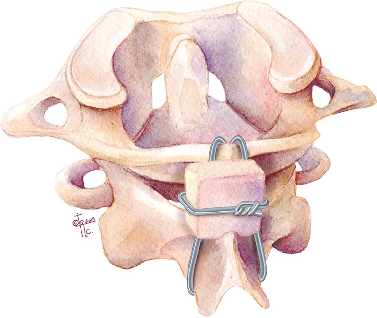
Illustration of the Gallie sublaminar technique. Wire placed under C1 posterior arch, looping around the C2 spinous process, and then performing “on-lay” fusion by placing iliac crest bone with a midline notch to dock onto the C2 lamina and spinous process.
In 1978, Brooks and Jenkins further modified the Gallie technique by placing two separate pieces of iliac crest bone graft between C1 posterior arch and C2 lamina on either side to improve rotation stability (Figure 2). In addition, they passed a separate sublaminar wire under both C1 and C2 laminae on each side to compress and secure each of the bone grafts in place. The C2 lamina was decorticated bilaterally and fashioned to receive the bone grafts accordingly to prevent inadvertent graft translation during compression of the sublaminar wires. This technique increased rotational stability, and decreased the C1–2 fusion failure rate to about 30% (3,18). However, the drawbacks of this technique were increased risk for potential spinal cord injury from the passing of two separate sublaminar wires under both C1 and C2 laminae, and increased operative time from preparing two separate bone grafts.
Figure 2.
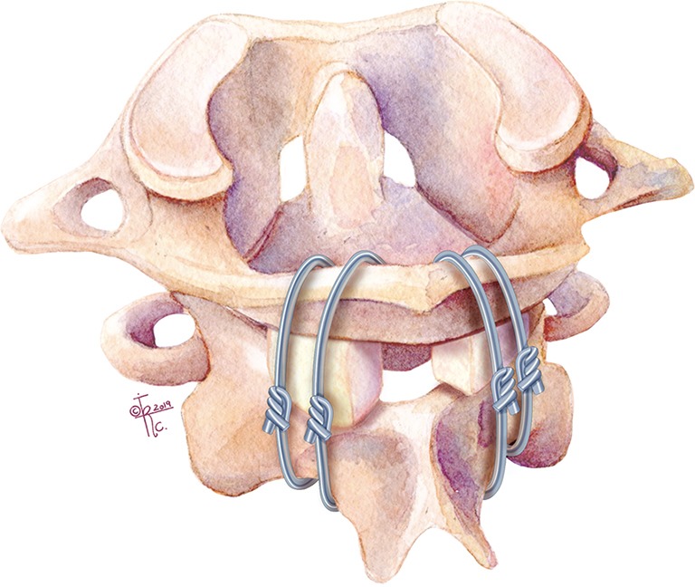
Illustration of the Brooks and Jenkins sublaminar technique. Modification of the Gallie technique by placing two separate pieces of iliac crest bone graft between C1 posterior arch and C2 lamina. In addition, there is a separate sublaminar wire under both C1 and C2 laminae on each side.
Dickman et al. showed another variation of the Gallie technique, named the Sonntag and Dickman technique in 1991 (20). In this technique, a single bicortical graft is wedged under the C1 posterior arch and C2 spinous process, with a single sublaminar wire passing under C1 and looping around C2 spinous process. The sublaminar wire below C1 is looped caudally behind the C2 spinous process thus trapping the bone graft between C1 and C2, thereby avoiding the inherent risk of a second sublaminar wire passage under C2. In conjunction with external fixation, up to 97% fusion rates have been reported (20).
Despite the improvement overtime, sublaminar wiring techniques still require the C1 posterior arch and C2 lamina/spinous processes to be intact to achieve stabilization. The long-term success of these procedures is dependent on achieving bony arthrodesis; thus, proper tightening of the sublaminar wires, proper placement/wedging of the bone graft, and thorough decortication of bony interfaces are essential. The sublaminar passage of the wire carries inherent risk of spinal cord injury, which cannot be overemphasized and must be done with great care.
In addition, the wiring techniques alone do not provide sufficient internal stabilization. Therefore, continued rigid external cervical orthosis is required post-operatively, which can be cumbersome and may negatively affect the patients’ quality of life (3,20,21). Today, sublaminar wiring is rarely performed as a stand-alone procedure, but is often utilized with other C1–2 fusion techniques to provide a stronger biomechanical construct.
Clamps, Hooks and Claws
In 1975, Tucker first described using interlaminar clamps for stabilizing subaxial cervical fractures (22). In 1984, Holness et al. reported long term outcome of this technique in 51 patients with cervical instability, which included one patient with C1–2 instability (Figure 3). The interlaminar clamping method for C1–2 stabilization was later known as the Halifax technique (23). The technique utilizing clamps obviated the need for sublaminar wire passage, thus minimizing the risk of inadvertent spinal cord injury. However, similar to sublaminar wiring, it requires intact posterior bony elements at C1–2, which may not always be the case in the setting of trauma. In addition, bony decompression cannot be performed due to the need to preserve the posterior elements of C1 and C2. Further, a piece of bone graft must be fitted and inserted between C1 posterior arch and C2 lamina to prevent clamp loosening from neck hyperextension and to facilitate bony arthrodesis.
Figure 3.
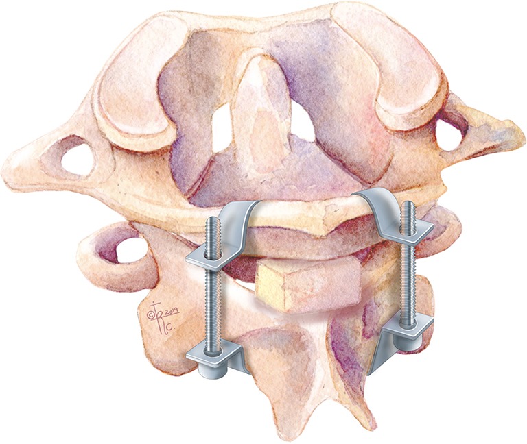
Illustration of Halifax technique (interlaminar clamps).
In 1992, the Apofix clamp was developed for posterior C1–2 stabilization. Similar to the Halifax clamps, an upper clamp is inserted above the C1 posterior arch, and a lower clamp is placed below the C2 lamina. A bone graft is then wedged between C1 posterior arch and C2 lamina to prevent clamp loosening during extension and to optimize arthrodesis. Sequential alternating tightening of the clamps then compresses and stabilizes the C1–2 segment. However, the interlaminar bone graft pose the potential risk of dislodging into the spinal canal without the security of a wire ventrally. These techniques provided a similar fusion rate to the Brooks-Jenkins technique. Similarly, clamp fixation provided poor rotational stability despite excellent resistance to flexion/extension. Thus, hardware failure, nonunion, clamp loosing and pseudoarthrosis were common problems with this construct.
Hanimoglu et al. (24) demonstrated a technique utilizing a C1–2 claw construct in a small case series that showed adequate results. The technique itself is a variation of interlaminar clamp fixation, however it has the application of a cross-connector aimed at increasing rotational strength and stabilization. However, this is a good option in the event that instrumentation of C1 and C2 proves difficult or unsafe. But, similar to the sublaminar wiring, all these techniques require intact laminae at the fusion levels and make posterior bony decompression at the fusion levels impossible.
Transarticular screw fixation
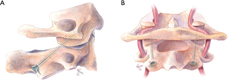
In 1979, Magerl and Seemann first introduced the transarticular screw (TAS) fixation of C1–2, which they later published in 1987 (25). With this technique, threaded screws were inserted into the C2 pars, traversing across the atlantoaxial facet joints, finally with the tips of screws ending in the C1 lateral masses (Figure 4) (8). The entry point is about 3 mm medial and 3 mm cranial from the medial margin of C2–3 facet joint. Dissecting medially with a Penfield #4 can help to expose the C2 pedicle and define the medial edge of the screw passage. The screw is directed toward the C1 anterior arch in the sagittal plane under fluoroscopic guidance, and directed 0º to 10º medially in the axial plane. Gallie sublaminar wiring is usually performed to provide additional fixation. If the posterior arch of the atlas is not intact and Gallie fusion is unable to be completed, direct atlantoaxial lateral joint fusion can be performed (26). As sublaminar wiring has an inherent risk of spinal cord injury during placement, there has been a push by some surgeons to utilize a C1–2 TAS and C1 hook instead (27,28), however there is some thought that further internal fixation is not necessary (29).
Figure 4.
Illustration of transarticular screw (TAS). Threaded screws inserted into C2 pars ending in the C1 lateral masses. (A) Sagittal and (B) coronal planes.
The TAS method provided superior biomechanical stability, avoided potential complications from passing the sublaminar wire, and allowed for posterior laminectomy for decompression if spinal stenosis were present. In addition, the rigid internal fixation from TAS eliminated the need for postoperative cervical collar or halo bracing, thus simplified the post-operative care and improved the quality of life for patients in the post-operative period. The TAS technique provided much higher fusion rate compared to various sublaminar wiring techniques, with multiple series demonstrating excellent clinical outcome with fusion rates ranging from 92–100% (30-32).
Biomechanical studies have shown that the C1–2 transarticular screw fixation allows the stiffest stabilization with the least amount of rotation and lateral bending. It is considered the “gold standard” for posterior C1–2 fusion. However, the TAS technique is technically challenging, requiring a separate incision for screw insertion due to the steep cranial-caudal angle of the screw trajectory, thus prohibiting its use in patients with severe upper thoracic kyphosis (26). More importantly, there is the potential risk for vertebral artery injury. The rate of VA injury for TAS has been reported to be as high as 8.2% (33). One important factor for VA injury during TAS placement is the variable course of VA in the C2 region, resulting high variability in the height and width of the isthmus of C2 through which the TAS is inserted. Any pathology or anomalous anatomical structure that may interfere with this trajectory is a contraindication for this technique. Thus, the C1 and C2 bony and vascular anatomy must be carefully evaluated with preoperative MRI and CT angiogram.
C1 lateral mass screw–C2 pars screw fixation with plates (Goel technique)
In 1994, Goel and Laheri described a new posterior fixation technique using C1 lateral mass-C2 pars screws construct connected by posterior cervical plates, which provided rigid posterior fixation and a reported 100% fusion rate in an early cohort of 30 patients (Figure 5), and subsequently a larger cohort of 160 cases with atlantoaxial instability during the 14-year follow-up period (6,34). The technique provided immediate, rigid, segmental internal fixation which permitted earlier mobilization. On-lay and interfacet bone grafts where subsequently placed to facilitate bony fusion. Direct screw fixation into the atlas and axis allowed firm bony purchase in the thick and large cortico-cancellous lateral mass, and provided a biomechanically strong segmental fixation. Of note, the Goel technique requires the ligation of the C2 nerve root for placement of the metal plate, which can result in postoperative posterior scalp numbness in 11.6% patients (35). Plate and screw fixation have never become popular but it gave a good foundation for the screw-rod fixation system.
Figure 5.
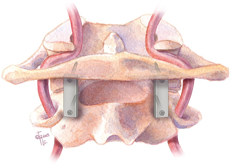
Illustration of Goel and Laheri technique. Posterior C1 lateral mass-C2 pars screws connected by posterior cervical plates.
To perform C1–2 fusion using the Goel technique, the C2 nerve root is sacrificed proximal to the C2 ganglion to facilitate the exposure of the C1–2 facet joint. The medial wall of the C1 lateral mass can be readily palpated with a Penfield dissector, which serves as the medial border of the screw trajectory. The entry point for the C1 lateral mass screw is at the center of the C1 lateral mass in the medial-lateral direction, and at or slightly inferior to the junction of the posterior arch and the inferior lateral mass in the cranial-caudal direction. It should be noted that the vertebral artery often runs in the sulcus arteriosus on the superior-lateral aspect of the C1 posterior arch, thus care must be taken to avoid inadvertent injuring to the vertebral artery during drilling in this area.
Using fluoroscopy, a 3 mm drill bit with drill guide are used to drill a pilot hole with 5° to 10° of medial angulation to penetrate the anterior cortex of C1. On lateral fluoroscopic images, the drill is aimed towards and slightly caudal to the anterior tubercle of C1 in the cranial-caudal direction; this will avoid possible violation of the atlanto-occipital joint if the drill is aimed too cranially. The drill bit is advanced slowly up to the posterior bony margin of the C1 anterior tubercle, which prevents excessive screw length beyond the anterior cortex of the C1 arch. The hole is then tapped, and the C1 lateral mass screw is placed after measuring the screw length with a feeler probe (usually 34 to 36 mm).
A C2 pars screw is then placed with a trajectory similar to the C1–2 transarticular screw, except that the pars screw is much shorter, usually 16 to 18 mm in length. The entry point for the C2 pars screw is about 3 mm cranial and 3 mm lateral from the medial border of the C2–3 facet joint. The screw should be parallel to the C2 pars in the sagittal plane, and parallel to the medial border of the pars in the axial plane.
Inadvertent vertebral artery injury can still occur with this technique, although the risk is not as high the transarticular screw technique (36). The risk is especially high if vertebral artery anatomy is altered with fenestrated vertebral artery or persistent first intersegmental artery.
C1 lateral mass screw—C2 pedicle screw fixation with rods (Harms technique)
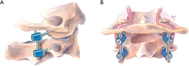
In 2001, Harms and Melcher reported a modification of the Goel technique utilizing C1 lateral mass screws and C2 pedicle screws connected by rods (Figure 6). They reported 100% fusion rate in their series (37). Since then, the Harms technique has been widely adapted by spine surgeons.
Figure 6.
Illustration of the Harms technique. Modification of the Goel technique in which C1 lateral mass screws are connected to C2 pedicle screws by rods. (A) Sagittal and (B) coronal planes.
To perform the C1–2 fusion using the Harms technique, the C2 nerve root is retracted caudally to expose the C1 lateral mass. The C1 screw entry point is at the middle of the junction of the C1 posterior arch and the midpoint of the posterior inferior part of the C1 lateral mass. After marking the entry point with a burr, drilling the trajectory, and tapping the screw hole similar to the Goel technique, a 3.5 mm polyaxial screw of an appropriate length is inserted into the lateral mass of C1 to achieve bicortical bony purchase. For the Harms technique, the entry point of the C2 pedicle screw is at the cranial and medial quadrant of the lateral mass. The screw trajectory is directed about 20° to 30° medially and cranially, parallel to the superior and medial surface of the C2 isthmus. Then the screw hole is tapped, and a 3.5 mm polyaxial screw of the appropriate length is inserted to gain bicortical purchase. A rod is then used to connect C1 and C2 screws to complete the screw-rod construct to achieve segmental stabilization. For arthrothesis, cancellous iliac bone graft can be harvested from the posterior iliac crest, or allograft can be placed over the decorticated posterior C1 and C2 lamina surfaces to facilitate arthrodesis.
The screw fixation techniques (TAS, Goel, Harms) all can be used in patents who have compromised posterior elements such as fractures of the lamina. The Harms Screw-rod technique allows for easier preservation of C2 ganglion than Goel screw-plate fixation system. The screw-rod system can also be used to reduce the C1–2 region and has less complications when compared with placement of transarticular screws (38-43). This construct of bilateral C2 pedicle screws combined with standard bilateral C1 lateral mass screws was considered the “gold standard” of maximal stability by some authors (44). Therefore, this technique has been widely accepted by many spine surgeons in the world and become more and more popular (45). However, copious bleeding can occur from venous plexus and irritation to C2 nerve root. A review article showed that C2 pedicle screw and the C2 pars screw are both broadly used for C1–2 fusion, and it demonstrated a slightly higher rate of successful fusion treated in patients treated with bilateral pedicle screw fixation compared with those with pedicle and pars hybrid or bilateral pars screw constructs (99.8% vs. 95.6%) (44).
Other choices of C1 screw fixation
C1 “pedicle” screw fixation
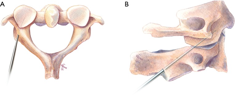
In 2002, Resnick and Benzel first demonstrated the clinical utility of C1 “pedicle” screw technique with the assistance of stereotactic guidance (46). Several anatomical studies have raised the possibility of placing C1 lateral mass screws through the “pedicle analog” of the posterior arch (46-49). Ultimately this leads to screw placement of the C1 lateral mass by way of the posterior arch (Figure 7), aptly named C1 posterior arch screw fixation (46,50,51). Advantages of this trajectory includes higher pull out strength over a traditional trajectory and avoidance of the neurovascular elements including the C2 nerve root and venous complex, with shorter operative times, and fewer postoperative complications (51-56). Thus, the C1 pedicle screw technique has been widely applied (51,52,57-59) and many techniques of C1 pedicle screw placement have been reported (48,49,60-62).
Figure 7.
Illustration of “pedicle” screw fixation. Insertion of C1 lateral mass screw via the posterior arch. (A) Axial and (B) sagittal planes.
A comparative study showed that overall screw placement success for these techniques was from 50% to 92%. However, none of the previously described approaches is absolutely safe because of significant anatomic variability (61). Currently, a C1 posterior arch of at least 4 mm is required for adequate placement of a pedicle screw (47,48,61). However, Huang et al. showed that a 3.5 mm screw can be adequately placed in the C1 pedicle in a safe fashion even is the pedicle height is <4 mm (60). Furthermore, there may be an increased risk for vertebral artery injury if there is a deep sulcus arteriosus, or if ponticulus posticus is present preventing superior retraction of the vertebral artery.
C1 notching technique
Other authors have adjusted C1 lateral mass screw placement utilizing a slightly more cranial entry, which is called the C1 notching technique (55,63,64). The entry point is between the entry point of C1 lateral mass screw and that of C1 “pedicle” screw, which is at the junction of the C1 posterior arch and lateral mass, and a little farther from paravertebral venous plexus and C2 nerve root. This higher-than-normal entry point decreases the venous bleeding and the risk for C2 nerve injury (63). Others have pointed out that the C1 notching is an alternative of the previously described technique by Yeom et al. of C1 posterior arch screw placement (51). However, the risk of vertebral artery injury is higher compared to the conventional entry point of C1 lateral mass screw, which is more caudal.
C1 posterior arch crossing screw technique
Several basic studies have shown the ability to place a screw in the C1 posterior arch crossing from ipsilateral to contralateral sides (crossing screw technique) in selected adult patients (65) and even in some of pediatric patients over 7 years but contraindicated in patients under age 6 years (66). C1 posterior arch crossing screw technique can provide rigid stabilization in C1–2 fixation in a biomechanical experiment (Figure 8) (65). This technique can reduces the possibility of injury to the paravertebral venous plexus and C2 nerve root, even though the clinical application has not been reported.
Figure 8.
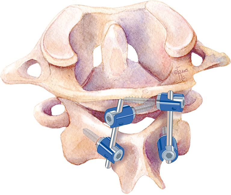
Illustration of C1 posterior arch crossing screw technique. Insertion of crossing screw into the C1 posterior arch.
Other choices of C2 screw fixation
C2 intralaminar screw fixation
In 2005, Wright reported a technique using translaminar screws as fixation points at C2, which provided an alternative C2 screw fixation option to connect with the C1 lateral mass screws, and they achieved 100% fusion rate in the series (Figure 9) (67). This C2 screw fixation technique does not place the vertebral artery at risk. Jea et al. modified Wright’s technique for placement of bilateral crossing C2 translaminar screws (68). Another modification was applied by removal of the upper part of the spinous process of C2 and the entry point of the screw was in the base of this removed spinous process. But this technique is not suitable for bilateral translaminar screw placement (69).
Figure 9.
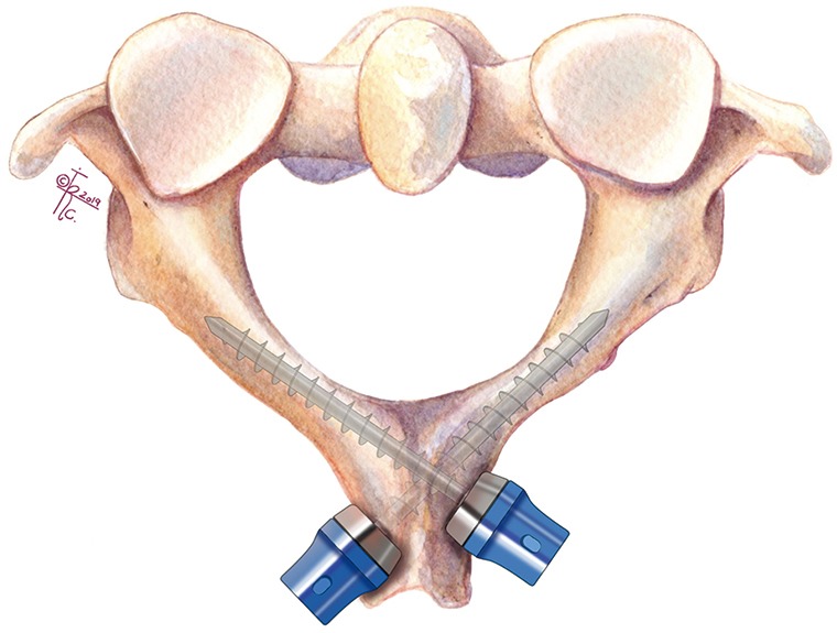
Illustration of C2 intralaminar screw fixation. Insertion of translaminar screws as fixation points at C2 to connect with C1 lateral mass screws.
A biomechanical study showed that translaminar screws appear to provide stronger and more reproducible fixation than pars screws, but neither of them is stronger than pedicle screws (70). Many clinical applications show excellent outcomes of this technique and a 97.6% fusion rate has also been reported in a case series (71-75). This technique makes the surgery less technically demanding and has a lower risk of injury to the vertebral artery, thus it is seen as a salvage technique in the instance of unsuccessful C2 pedicle screw placement or instances of high riding vertebral artery (70,73). However, Wang indicated that the unique position of the screw heads may result in increased stress and strain on the intralaminar screws, and recommends larger diameter screws or additional fixation points at adjacent levels (75).
When the posterior elements are injured or incompetent and wire passage or clamp positioning is not possible, posterior screw fixation can provide stabilization. Internal screw fixation with local autograft or allograft is superior in strength and fusion rates when compared with wiring techniques (76). Posterior screw fixation techniques, such as transarticular screw, plate-screw and rod-screw techniques, are recent alternative methods of posterior C1–2 fixation. Screw fixation of the posterior cervical spine typically yields higher fusion rates because of increased stiffness in rotation and translation than posterior wiring techniques. In addition, it obviates the need for postoperative rigid external halo immobilization (68).
Hybrid constructs
Hook-screw fixation
Although hooks were initially used to treat thoracolumbar deformities, they have also been used to stabilize atlantoaxial junction for fusion. Several morphologic or biomechanical studies and clinic application have demonstrated the safety and effectivity of hook combined with screw fixation for C1–2 fusion.
C1 hook combined with C2 screw (Figure 10)
Figure 10.
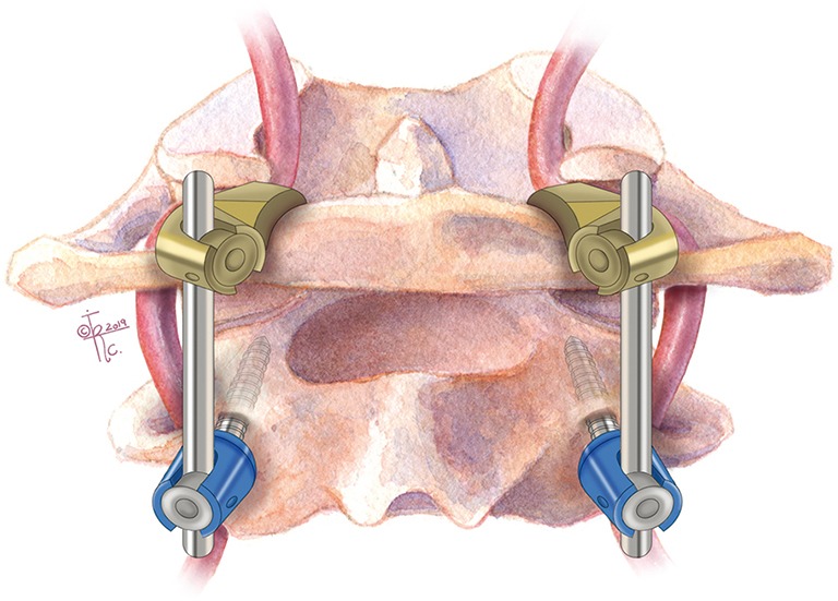
Illustration of C1 hook combined with C2 pedicle screw.
Aydinli et al. reported C1 hook in combination with C2 pedicle screw fixation for treatment of 2 cases odontoid fracture, in 2008 (77). In 2010, Ni et al. reported application of the technique as an alternative surgical approach to treat atlantoaxial instability for fusion. Thirteen patients were treated with this technique showing good rates of fusion and clinical endpoint (78). Since then, other authors also reported the technique with similar results (79-81). The technique is simple and minimizes the risk of neurovascular injuries. The technique is not very popular and the limited cases have been reported. The authors think that C1 hook combined with C2 par/laminar screw might be reasonable but few cases are reported recently (82).
C1 hook combined with C1–2 transarticular screw
Clinical application of C1 hook combined with C1–2 transarticular screw fixation has been reported by multiple studies (27,28,82-84). These studies show excellent results and satisfactory fusion rates, including long-term follow up outcomes of this technique (27). Biomechanical studies of the combination technique have also validated the effect of hybrid rigid fixation (85-87). A retrospective comparative study showed that C1 hook combined with C1–2 transarticular screw fixation was comparable to C1 lateral mass screw combined with C2 pedicle screw fixation in terms of fusion rate and functional outcomes for treating reducible atlantoaxial dislocation (88). The C1 cook technique is not technically difficult, however the C1–2 transarticular screw technique remains a challenge for some surgeons in select cases.
Screw-claw-rod fixation
In 2012, Reis et al. reported a biomechanical test of a novel screw-claw-rod technique for C1–2 fixation. The technique includes opposing laminar hooks (claw) at C2 combined with C1 lateral mass screw and has been shown to have similar results to the Harms technique (89) This technique can decrease the risk of vertebral artery injury in theory. It also can be a salvage in failed C2 screw or transarticular screw even though the report of clinical application of this technique has not been seen now.
C1–2 interfacet spacers
In 2007, Goel descried another method of C1–2 stabilization using stand-alone interfacet spacers, in which titanium spacers were inserted into the bilateral C1–2 facet joints. The author achieved 100% fusion rate in a small series of four patients (5).
Thus, C1–2 fixation techniques developed over the last century can be summarized into these categories: (I) sublaminar wiring/interlaminar clamps with bone graft, (II) transarticular screws, and (III) C1 lateral mass screws with C2 pars/pedicle/translaminar screws. Knowledge and familiarity of these various techniques will allow spine surgeons to adapt accordingly if a vascular anomaly prevents safe placement of instrumentation for a particular technique.
C2 nerve root
The anatomy of the neural foramen at C1–2 is unique compared to the rest of the subaxial spine as it is bordered superiorly by the C1 posterior arch, inferiorly by the C2 lamina, anteriorly by the atlantoaxial joint, and posteriorly by the inferior edge of the C1 posterior arch and atlantepistorphic ligament (90). The C2 nerve root separates from the spinal cord under the C1 posterior arch and exits from the spinal canal to the atlanto-axial interlaminar space through the neural foramen at C1–2 (91). Impingement of the C2 nerve root most often occurs between the inferior edge of the C1 posterior arch and the ventral osteophytes of the lateral atlanto-axial joint. Given the small corridor of the C1–2 neural foramen, mechanical compression secondary to joint arthrosis or placement of a posterior C1 lateral mass screw may lead to C2 neuropathy/radiculopathy. The C2 nerve root lies over the C1–2 joint which is a desired location for joint decortication and autograft/allograft placement. Extensive manipulation of the C2 nerve root can result in C2 neuralgia.
Although the C1–2 neural foramina may be a small working corridor, using various surgical techniques provides an opportunity to preserve the C2 nerve root. Yeom et al. used C1 posterior arch screws instead of conventional lateral mass screws (92). This allowed C1–2 facet joint distraction and bone block insertion while preserving the C2 root without any complications of radiculopathy/neuropathy. We also favor using this technique and preserving the C2 nerve root to minimize any C2 neuralgia after surgery. However, there is a slight increased risk of vertebral artery injury, hence pre-operative evaluation for any vertebral anomalies is crucial.
On the other hand, Goel et al. favors C2 neurectomy. In one of the largest series’ of patients undergoing C1–2 fixation, Goel et al. sectioned 108 C2 nerve roots proximal to the ganglion (93). By removing the C2 nerve root, there was better exposure of the C1–2 joint. Once the joint is decorticated, cervical interfacet allograft spacers can be placed. These allograft spacers are under compression which promote fusion and stiffens the segment. This also helps load-share with the instrumentation which is particularly important in the setting of osteoporosis (94). Overall, the results regarding C2 resection are mixed but there is a fair amount of evidence that C2 resection is tolerated by patients and may help with intraoperative exposure and instrumentation (16).
Vascular anomalies in the CVJ
Anomalies of the vertebral artery (VA) at the craniovertebral junction (CVJ) include: (I) persistent first intersegmental artery (PFIA), (II) fenestrated vertebral artery (FVA), (III) low-lying posterior inferior cerebellar artery (PICA) and (IV) high-riding vertebral artery (HRVA) (9-11,13,14). These vascular anomalies increase the complexity and risk of vascular injury during C1–2 instrumentation, especially with the popularity of C2 neurectomy and placement of C1 lateral mass screws. The versatility of surgical techniques outlined in this review, would allow modification of the intended instrumentation techniques in presence of any particular anomaly.
In the case of PFIA, the VA inserts into the dura below the C1 posterior arch, after coming out from the C2 transverse foramen. It courses under the C1 posterior arch, entering the dura without passing through the C1 transverse foramen (95). In FVA, a PFIA is present but the normal course of VA is also present, thus forming a loop or fenestration. Therefore, one branch of the VA follows the course of PFIA ascending under the C1 arch, while the other ascends through the C1 transverse foramen along the natural path of the VA, then they unite above the C2 arch and reform the vertebral artery. PICA can also originate from the vertebral artery in the C1–2 region and thus prone to be injured during screw placement if not recognized. HRVA occurs when the vertebral artery has a course that is too medial and/or too cranial, which can be seen on CT by the medial or cephalad location of the C2 transverse foramen (96). This would in turn decrease the height of the C2 isthmus and place the vertebral artery in the path of the TAS, thus making evaluation of a preoperative CT universal in cases where a TAS placement is planned. Additional bone anomalies to be recognized is the formation of a bony connection between the posterior superior articular process and posterolateral arch of the atlas. This has been termed ponticulus posticus, arcuate foramen, or canalis vertebralis (97). The ponticulus posticus has been shown to be present in early primates and postulated to be an evolutionary remnant (98).
During embryogenesis, formation of the vertebral artery occurs from plexiform anastomoses of cervical intersegmental arteries at five to six weeks of gestation (99). There are seven intersegmental arteries which ultimately enlarge and from the subclavian and vertebral arteries. In case where the first intersegmental artery (FIA) persists, the vertebral artery takes an anomalous course entering the spinal canal between C1/2. This is known as a persistent first intersegmental artery. A fenestrated vertebral artery occurs when there is normal vertebral artery development in conjunction with a persistent first intersegmental artery (100). Variation of normal anatomy to be considered as well include a low-lying PICA and HRVA. Some authors also suggested that the destruction of the atlantoaxial joint in rheumatoid arthritis patients could result in a relatively high VA groove and a narrower isthmus (10).
The overall incidence of vascular anomalies which can complicate a C1/2 fusion is relatively low. It is important to keep in mind the relative prevalence of their vascular anomalies. The incidence of PFIA is 0.6% to 4.7%. For FVA it is 0.24% to 1.3%. In the case of a low-lying PICA it is 0.67% to 1.3%. Finally the reported incidence of HRVA is 11.7% to 23% and for ponticulus posticus a wide range of 5.0% to 52.94% has been reported (9,18,33,95,100-102). It has been shown that the rate of vascular anomalies is higher in patients with simultaneous bony anomalies at craniovertebral junction (95,103). Embryologically this is intuitive as segmentation of sclerotomes and vascular rearrangements occur at similar stages. Thus, there should be high suspicion of vascular anomalies in patients presenting with os odontoideum or occipitalization of C1 (95). Miyata also reported that rheumatoid arthritis (RA) is a significant risk factor for the presence of HRVA (10).
Recognition of vascular anomalies preoperatively can reduce the risk of intraoperative injury C1–2 instrumentation. The use of CT has become universal for planning of surgical instrumentation in patients with CVJ anomalies. While a high-resolution CT is often adequate to detect the presence of HRVA and posticus ponticus, it may be inadequate to identify various other vascular anomalies as described above. There should be a low threshold to consider some form of vascular imaging, most commonly a CTA, to identify these vascular anomalies especially if there is any suspicion on preoperative MRI or CT of the cervical spine. A study by Sardhara et al. showed an overall risk of 35.4% for vascular injury in cases of the previously mentioned variances (12). With respect to a high riding vertebral artery, Wright et al. reported a rate of 4.1% vertebral artery injury during transarticular screw fixation in a cohort of 1,318 patients. They also showed that complications form VA injury were severe, including cerebellar and brainstem infarction (104).
With C2 neurectomy often performed during placement of lateral mass screws, the possibility of a vertebral artery injury can be significant, especially in presence of anomalies such as inverted vertebral artery or FIA (105).
It may be dangerous to insert the C1 lateral mass screw from the point of the inferior lateral mass if the VA courses along the caudal side of the C1 arch, such in the case of PFIA or FVA (102). If there is enough space between the anomalous VA and the entry point to the C1 lateral mass, the lateral mass screw can be inserted by predetermining the entry point, as described by Hong et al. (106). In these cases, the Magerl technique with TAS can help to avoid VA injury. If a HRVA is also present and prevents TAS, then the fixation may be extended to the occiput, skipping fixation at C1. Various C2 fixation techniques include pedicle, pars, or translaminar screws. If none of these fixation points are feasible, then the instrumentation can be extended down to C3. Attention should also be paid to the dominance of vertebral arteries. Patients with injuries to the non-dominant vertebral artery are often asymptomatic; where as an injury to the dominant VA can cause brain stem infarct and even death. Thus, posterior C1–2 stabilization on the side of the dominant VA should be undertaken with extra precaution.
In the case of a persistent first intersegmental artery, there are multiple surgical approaches described for C1–2 fixation (107). Typically, stabilization is performed with fixation to the occiput, skipping screw placement in C1. Alternatively, a screw may be placed in the posterior arch of C1 (108). In doing this, the C1 arch is placed at risk of splitting, thus care must be taken in this approach. In some cases, C1 fixation with a screw entering C1 above the arch may be feasible (77). An alternative approach of lateral mass fixation utilizing an entry point below the arch, has been reported by Lee et al. (109).
As previously stated, care should be taken to identify these vascular anomalies. In the case of PFIA, FVA and low-riding PICA, they may obscure the trajectory for the C1 lateral mass screw. If a certain vascular deviation compromises the entry point, serious complications can be avoided by choosing a starting point at the superior lateral mass of C1.
Case example
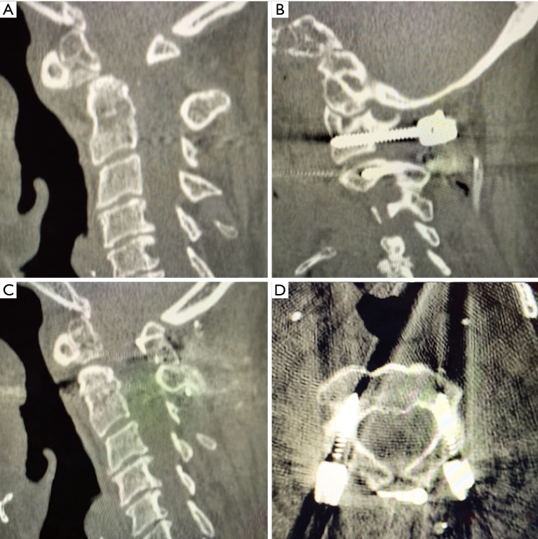
In this example we show a case of a patient with a C2 odontoid fracture with anterolisthesis and spinal cord compression who underwent a combination of the described techniques (Figure 11A). The patient underwent C1 lateral mass, C2 pedicle screw fixation with sublaminar wiring (Figure 11B,C,D).
Figure 11.
Example of case in which C1 lateral mass and C2 pedicle screw fixation with sublaminar wiring were used. (A) Sagittal CT of pre-reduction os odontoideum; (B) parasagittal CT of C1–C2 fixation using lateral mass and pars screws; (C) sagittal CT of post-reduction os odontoideum; (D) axial CT demonstrating pars screw placement in C2.
Conclusions
Posterior C1–2 fusion techniques have improved greatly over time and multiple different approaches to atlantoaxial have been introduced. Rigid internal atlantoaxial fixation is the key factor for C1–2 fusion. As discussed, the C1–2 transarticular screw approach has been shown to be a superior approach to atlantoaxial fixation, while more and more authors recommend C1 pedicle/lateral mass screw combined with C2 pedicle/pars screw fixation as primary choice. Other screw or/and hook fixation techniques may be used alternatives or salvages for C1–2 fusion. Wiring technique and interlaminar clamp techniques have been largely phased out, reserved for use in select cases. Our discussion of the regional and abhorrent anatomy highlights the importance of surgeons to become familiar with individual patient anatomy preoperatively and exercise proper judgement during the procedure, ultimately with the goal of safe instrumentation and successful C1–2 stabilization to avoid potentially devastating complications.
Acknowledgments
Funding: None.
Ethical Statement: The authors are accountable for all aspects of the work in ensuring that questions related to the accuracy or integrity of any part of the work are appropriately investigated and resolved.
Open Access Statement: This is an Open Access article distributed in accordance with the Creative Commons Attribution-NonCommercial-NoDerivs 4.0 International License (CC BY-NC-ND 4.0), which permits the non-commercial replication and distribution of the article with the strict proviso that no changes or edits are made and the original work is properly cited (including links to both the formal publication through the relevant DOI and the license). See: https://creativecommons.org/licenses/by-nc-nd/4.0/.
Footnotes
Provenance and Peer Review: This article was commissioned by the Guest Editors (Lee A. Tan and Ilyas S. Aleem) for the series “Advanced Techniques in Complex Cervical Spine Surgery” published in Journal of Spine Surgery. The article was sent for external peer review organized by the Guest Editors and the editorial office.
Conflicts of Interest: The series “Advanced Techniques in Complex Cervical Spine Surgery” was commissioned by the editorial office without any funding or sponsorship. LAT serves as the unpaid editorial board member of Journal of Spine Surgery from Jan. 2019 to Jan. 2021 and served as the unpaid Guest Editor of the series. The other authors have no conflicts of interest to declare.
References
- 1.Nakajima K, Onomura T, Tanida Y, et al. Factors related to the severity of myelopathy in atlantoaxial instability. Spine (Phila Pa 1976) 1996;21:1440-5. 10.1097/00007632-199606150-00008 [DOI] [PubMed] [Google Scholar]
- 2.Ringel F, Reinke A, Stuer C, et al. Posterior C1-2 fusion with C1 lateral mass and C2 isthmic screws: accuracy of screw position, alignment and patient outcome. Acta Neurochir (Wien) 2012;154:305-12. 10.1007/s00701-011-1224-x [DOI] [PubMed] [Google Scholar]
- 3.Brooks AL, Jenkins EB. Atlanto-axial arthrodesis by the wedge compression method. J Bone Joint Surg Am 1978;60:279-84. 10.2106/00004623-197860030-00001 [DOI] [PubMed] [Google Scholar]
- 4.Gallie WE. Skeletal traction in the treatment of fractures and dislocations of the cervical spine. Ann Surg 1937;106:770-6. 10.1097/00000658-193710000-00026 [DOI] [PMC free article] [PubMed] [Google Scholar]
- 5.Goel A. Atlantoaxial joint jamming as a treatment for atlantoaxial dislocation: a preliminary report. Technical note. J Neurosurg Spine 2007;7:90-4. 10.3171/SPI-07/07/090 [DOI] [PubMed] [Google Scholar]
- 6.Goel A, Laheri V. Plate and screw fixation for atlanto-axial subluxation. Acta Neurochir (Wien) 1994;129:47-53. 10.1007/BF01400872 [DOI] [PubMed] [Google Scholar]
- 7.Goel A, Laheri V. Re: Harms J, Melcher P. Posterior C1-C2 fusion with polyaxial screw and rod fixation. (Spine 2001;26: 2467-71). Spine (Phila Pa 1976) 2002;27:1589-90. 10.1097/00007632-200207150-00027 [DOI] [PubMed] [Google Scholar]
- 8.Grob D, Magerl F. Surgical stabilization of C1 and C2 fractures. Orthopade 1987;16:46-54. [PubMed] [Google Scholar]
- 9.Hong JT, Lee SW, Son BC, et al. Analysis of anatomical variations of bone and vascular structures around the posterior atlantal arch using three-dimensional computed tomography angiography. J Neurosurg Spine 2008;8:230-6. 10.3171/SPI/2008/8/3/230 [DOI] [PubMed] [Google Scholar]
- 10.Miyata M, Neo M, Ito H, et al. Is rheumatoid arthritis a risk factor for a high-riding vertebral artery? Spine (Phila Pa 1976) 2008;33:2007-11. 10.1097/BRS.0b013e31817c6bf7 [DOI] [PubMed] [Google Scholar]
- 11.OʼDonnell CM , Child ZA, Nguyen Q, et al. Vertebral artery anomalies at the craniovertebral junction in the US population. Spine (Phila Pa 1976) 2014;39:E1053-7. 10.1097/BRS.0000000000000447 [DOI] [PubMed] [Google Scholar]
- 12.Sardhara J, Behari S, Mohan BM, et al. Risk stratification of vertebral artery vulnerability during surgery for congenital atlanto-axial dislocation with or without an occipitalized atlas. Neurol India 2015;63:382-91. 10.4103/0028-3886.158218 [DOI] [PubMed] [Google Scholar]
- 13.Yamazaki M, Okawa A, Hashimoto M, et al. Abnormal course of the vertebral artery at the craniovertebral junction in patients with Down syndrome visualized by three-dimensional CT angiography. Neuroradiology 2008;50:485-90. 10.1007/s00234-008-0368-8 [DOI] [PubMed] [Google Scholar]
- 14.Yeom JS, Buchowski JM, Kim HJ, et al. Risk of vertebral artery injury: comparison between C1-C2 transarticular and C2 pedicle screws. Spine J 2013;13:775-85. 10.1016/j.spinee.2013.04.005 [DOI] [PubMed] [Google Scholar]
- 15.Ahn J, Duran M, Syldort S, et al. Arcuate Foramen: Anatomy, Embryology, Nomenclature, Pathology, and Surgical Considerations. World Neurosurg 2018;118:197-202. 10.1016/j.wneu.2018.07.038 [DOI] [PubMed] [Google Scholar]
- 16.Badhiwala JH, Nassiri F, Witiw CD, et al. Does Transection of the C2 Nerve Roots During C1 Lateral Mass Screw Placement for Atlantoaxial Fixation Result in a Superior Outcome?: A Systematic Review of the Literature and Meta-analysis. Spine 2017;42:E1067-76. 10.1097/BRS.0000000000002069 [DOI] [PubMed] [Google Scholar]
- 17.Coyne TJ, Fehlings MG, Wallace MC, et al. C1-C2 posterior cervical fusion: long-term evaluation of results and efficacy. Neurosurgery 1995;37:688-92; discussion 692-3. 10.1227/00006123-199510000-00012 [DOI] [PubMed] [Google Scholar]
- 18.Sen MK, Steffen T, Beckman L, et al. Atlantoaxial fusion using anterior transarticular screw fixation of C1-C2: technical innovation and biomechanical study. Eur Spine J 2005;14:512-8. 10.1007/s00586-004-0823-0 [DOI] [PMC free article] [PubMed] [Google Scholar]
- 19.Denaro V, Di Martino A. Cervical spine surgery: an historical perspective. Clin Orthop Relat Res 2011;469:639-48. 10.1007/s11999-010-1752-3 [DOI] [PMC free article] [PubMed] [Google Scholar]
- 20.Dickman CA, Sonntag VK, Papadopoulos SM, et al. The interspinous method of posterior atlantoaxial arthrodesis. J Neurosurg 1991;74:190-8. 10.3171/jns.1991.74.2.0190 [DOI] [PubMed] [Google Scholar]
- 21.Gallie WE. Fractures and dislocations of the cervical spine. The American Journal of Surgery 1939;46:495-9. 10.1016/S0002-9610(39)90309-0 [DOI] [Google Scholar]
- 22.Tucker HH. Technical report: method of fixation of subluxed or dislocated cervical spine below C1-C2. Can J Neurol Sci 1975;2:381-2. 10.1017/S0317167100020503 [DOI] [PubMed] [Google Scholar]
- 23.Holness RO, Huestis WS, Howes WJ, et al. Posterior stabilization with an interlaminar clamp in cervical injuries: technical note and review of the long term experience with the method. Neurosurgery 1984;14:318-22. 10.1227/00006123-198403000-00010 [DOI] [PubMed] [Google Scholar]
- 24.Hanimoglu H, Hanci L, Kaynar MY, et al. Bilateral C1-C2 claw for atlantoaxial instability. Turk Neurosurg 2009;19:345-8. [PubMed] [Google Scholar]
- 25.Magerl F, Seemann PS. Stable Posterior Fusion of the Atlas and Axis by Transarticular Screw Fixation. In: Kehr P, Weidner A (editors). Cervical Spine I: Strasbourg 1985. Vienna: Springer Vienna, 1987:322-7. [Google Scholar]
- 26.Jeanneret B, Magerl F. Primary posterior fusion C1/2 in odontoid fractures: indications, technique, and results of transarticular screw fixation. J Spinal Disord 1992;5:464-75. 10.1097/00002517-199212000-00012 [DOI] [PubMed] [Google Scholar]
- 27.Guo X, Ni B, Xie N, et al. Bilateral C1-C2 transarticular screw and C1 laminar hook fixation and bone graft fusion for reducible atlantoaxial dislocation: a seven-year analysis of outcome. PLoS One 2014;9:e87676. 10.1371/journal.pone.0087676 [DOI] [PMC free article] [PubMed] [Google Scholar]
- 28.Ni B, Zhou F, Xie N, et al. Transarticular screw and C1 hook fixation for os odontoideum with atlantoaxial dislocation. World Neurosurg 2011;75:540-6. 10.1016/j.wneu.2010.07.021 [DOI] [PubMed] [Google Scholar]
- 29.Wang C, Yan M, Zhou H, et al. Atlantoaxial transarticular screw fixation with morselized autograft and without additional internal fixation: technical description and report of 57 cases. Spine (Phila Pa 1976) 2007;32:643-6. 10.1097/01.brs.0000257539.75693.cc [DOI] [PubMed] [Google Scholar]
- 30.Farey ID, Nadkarni S, Smith N. Modified Gallie technique versus transarticular screw fixation in C1-C2 fusion. Clin Orthop Relat Res 1999:126-35. 10.1097/00003086-199902000-00013 [DOI] [PubMed] [Google Scholar]
- 31.Stillerman CB, Wilson JA. Atlanto-axial stabilization with posterior transarticular screw fixation: technical description and report of 22 cases. Neurosurgery 1993;32:948-54; discussion 954-5. 10.1227/00006123-199306000-00011 [DOI] [PubMed] [Google Scholar]
- 32.Taggard DA, Kraut MA, Clark CR, et al. Case-control study comparing the efficacy of surgical techniques for C1-C2 arthrodesis. J Spinal Disord Tech 2004;17:189-94. 10.1097/00024720-200406000-00005 [DOI] [PubMed] [Google Scholar]
- 33.Neo M, Matsushita M, Iwashita Y, et al. Atlantoaxial transarticular screw fixation for a high-riding vertebral artery. Spine (Phila Pa 1976) 2003;28:666-70. 10.1097/01.BRS.0000051919.14927.57 [DOI] [PubMed] [Google Scholar]
- 34.Goel A, Desai KI, Muzumdar DP. Atlantoaxial fixation using plate and screw method: a report of 160 treated patients. Neurosurgery 2002;51:1351-6; discussion 1356-7. 10.1097/00006123-200212000-00004 [DOI] [PubMed] [Google Scholar]
- 35.Kang MM, Anderer EG, Elliott RE, et al. C2 nerve root sectioning in posterior C1-2 instrumented fusions. World Neurosurg 2012;78:170-7. 10.1016/j.wneu.2011.07.010 [DOI] [PubMed] [Google Scholar]
- 36.Mummaneni PV, Haid RW. Atlantoaxial fixation: overview of all techniques. Neurol India 2005;53:408-15. 10.4103/0028-3886.22606 [DOI] [PubMed] [Google Scholar]
- 37.Harms J, Melcher RP. Posterior C1-C2 fusion with polyaxial screw and rod fixation. Spine (Phila Pa 1976) 2001;26:2467-71. 10.1097/00007632-200111150-00014 [DOI] [PubMed] [Google Scholar]
- 38.Elliott RE, Tanweer O, Boah A, et al. Outcome comparison of atlantoaxial fusion with transarticular screws and screw-rod constructs: meta-analysis and review of literature. J Spinal Disord Tech 2014;27:11-28. 10.1097/BSD.0b013e318277da19 [DOI] [PubMed] [Google Scholar]
- 39.Hott JS, Lynch JJ, Chamberlain RH, et al. Biomechanical comparison of C1-2 posterior fixation techniques. J Neurosurg Spine 2005;2:175-81. 10.3171/spi.2005.2.2.0175 [DOI] [PubMed] [Google Scholar]
- 40.Jeon SW, Jeong JH, Choi GH, et al. Clinical outcome of posterior fixation of the C1 lateral mass and C2 pedicle by polyaxial screw and rod. Clin Neurol Neurosurg 2012;114:539-44. 10.1016/j.clineuro.2011.11.001 [DOI] [PubMed] [Google Scholar]
- 41.Kim JY, Oh CH, Yoon SH, et al. Comparison of outcomes after atlantoaxial fusion with transarticular screws and screw-rod constructs. J Korean Neurosurg Soc 2014;55:255-60. 10.3340/jkns.2014.55.5.255 [DOI] [PMC free article] [PubMed] [Google Scholar]
- 42.Melcher RP, Puttlitz CM, Kleinstueck FS, et al. Biomechanical testing of posterior atlantoaxial fixation techniques. Spine (Phila Pa 1976) 2002;27:2435-40. 10.1097/00007632-200211150-00004 [DOI] [PubMed] [Google Scholar]
- 43.Richter M, Schmidt R, Claes L, et al. Posterior atlantoaxial fixation: biomechanical in vitro comparison of six different techniques. Spine (Phila Pa 1976) 2002;27:1724-32. 10.1097/00007632-200208150-00008 [DOI] [PubMed] [Google Scholar]
- 44.Elliott RE, Tanweer O, Boah A, et al. Comparison of safety and stability of C-2 pars and pedicle screws for atlantoaxial fusion: meta-analysis and review of the literature. J Neurosurg Spine 2012;17:577-93. 10.3171/2012.9.SPINE111021 [DOI] [PubMed] [Google Scholar]
- 45.Elliott RE, Tanweer O, Boah A, et al. Atlantoaxial fusion with screw-rod constructs: meta-analysis and review of literature. World Neurosurg 2014;81:411-21. 10.1016/j.wneu.2012.03.013 [DOI] [PubMed] [Google Scholar]
- 46.Resnick DK, Benzel EC. C1-C2 pedicle screw fixation with rigid cantilever beam construct: case report and technical note. Neurosurgery 2002;50:426-8. [DOI] [PubMed] [Google Scholar]
- 47.Christensen DM, Eastlack RK, Lynch JJ, et al. C1 anatomy and dimensions relative to lateral mass screw placement. Spine (Phila Pa 1976) 2007;32:844-8. 10.1097/01.brs.0000259833.02179.c0 [DOI] [PubMed] [Google Scholar]
- 48.Ma XY, Yin QS, Wu ZH, et al. Anatomic considerations for the pedicle screw placement in the first cervical vertebra. Spine (Phila Pa 1976) 2005;30:1519-23. 10.1097/01.brs.0000168546.17788.49 [DOI] [PubMed] [Google Scholar]
- 49.Tan M, Wang H, Wang Y, et al. Morphometric evaluation of screw fixation in atlas via posterior arch and lateral mass. Spine (Phila Pa 1976) 2003;28:888-95. 10.1097/01.BRS.0000058719.48596.CC [DOI] [PubMed] [Google Scholar]
- 50.Gebauer M, Barvencik F, Briem D, et al. Evaluation of anatomic landmarks and safe zones for screw placement in the atlas via the posterior arch. Eur Spine J 2010;19:85-90. 10.1007/s00586-009-1181-8 [DOI] [PMC free article] [PubMed] [Google Scholar]
- 51.Yeom JS, Kafle D, Nguyen NQ, et al. Routine insertion of the lateral mass screw via the posterior arch for C1 fixation: feasibility and related complications. Spine J 2012;12:476-83. 10.1016/j.spinee.2012.06.010 [DOI] [PubMed] [Google Scholar]
- 52.Elliott RE, Tanweer O, Frempong-Boadu A, et al. Impact of starting point and C2 nerve status on the safety and accuracy of C1 lateral mass screws: meta-analysis and review of the literature. J Spinal Disord Tech 2015;28:171-85. 10.1097/BSD.0b013e3182898aa9 [DOI] [PubMed] [Google Scholar]
- 53.Fensky F, Kueny RA, Sellenschloh K, et al. Biomechanical advantage of C1 pedicle screws over C1 lateral mass screws: a cadaveric study. Eur Spine J 2014;23:724-31. 10.1007/s00586-013-3143-4 [DOI] [PMC free article] [PubMed] [Google Scholar]
- 54.He B, Yan L, Xu Z, et al. Prospective, Self-controlled, Comparative Study of Transposterior Arch Lateral Mass Screw Fixation and Lateral Mass Screw Fixation of the Atlas in the Treatment of Atlantoaxial Instability. J Spinal Disord Tech 2015;28:E427-32. 10.1097/BSD.0b013e3182a35572 [DOI] [PubMed] [Google Scholar]
- 55.Pan J, Li L, Qian L, et al. C1 lateral mass screw insertion with protection of C1-C2 venous sinus: technical note and review of the literature. Spine (Phila Pa 1976) 2010;35:E1133-6. 10.1097/BRS.0b013e3181e215ff [DOI] [PubMed] [Google Scholar]
- 56.Zarro CM, Ludwig SC, Hsieh AH, et al. Biomechanical comparison of the pullout strengths of C1 lateral mass screws and C1 posterior arch screws. Spine J 2013;13:1892-6. 10.1016/j.spinee.2013.06.015 [DOI] [PubMed] [Google Scholar]
- 57.Chen JF, Wu CT, Lee SC, et al. Posterior atlantoaxial transpedicular screw and plate fixation. Technical note. J Neurosurg Spine 2005;2:386-92. 10.3171/spi.2005.2.3.0386 [DOI] [PubMed] [Google Scholar]
- 58.Elliott RE, Tanweer O, Smith ML, et al. Impact of Starting Point and Bicortical Purchase of C1 Lateral Mass Screws on Atlantoaxial Fusion: Meta-Analysis and Review of the Literature. J Spinal Disord Tech 2015;28:242-53. 10.1097/BSD.0b013e31828ffc97 [DOI] [PubMed] [Google Scholar]
- 59.Ma C, Wu J, Zhao M, et al. Treatment of upper cervical spine instability with posterior fusion plus atlantoaxial pedicle screw. Cell Biochem Biophys 2014;69:693-7. 10.1007/s12013-014-9854-2 [DOI] [PubMed] [Google Scholar]
- 60.Huang DG, He SM, Pan JW, et al. Is the 4 mm height of the vertebral artery groove really a limitation of C1 pedicle screw insertion? Eur Spine J 2014;23:1109-14. 10.1007/s00586-014-3217-y [DOI] [PubMed] [Google Scholar]
- 61.Lin JM, Hipp JA, Reitman CA. C1 lateral mass screw placement via the posterior arch: a technique comparison and anatomic analysis. Spine J 2013;13:1549-55. 10.1016/j.spinee.2013.06.006 [DOI] [PubMed] [Google Scholar]
- 62.Resnick DK, Lapsiwala S, Trost GR. Anatomic suitability of the C1-C2 complex for pedicle screw fixation. Spine (Phila Pa 1976) 2002;27:1494-8. 10.1097/00007632-200207150-00003 [DOI] [PubMed] [Google Scholar]
- 63.Lee SH, Kim ES, Eoh W. Modified C1 lateral mass screw insertion using a high entry point to avoid postoperative occipital neuralgia. J Clin Neurosci 2013;20:162-7. 10.1016/j.jocn.2012.01.045 [DOI] [PubMed] [Google Scholar]
- 64.Ma XY, Yin QS, Wu ZH, et al. C1 pedicle screws versus C1 lateral mass screws: comparisons of pullout strengths and biomechanical stabilities. Spine (Phila Pa 1976) 2009;34:371-7. 10.1097/BRS.0b013e318193a21b [DOI] [PubMed] [Google Scholar]
- 65.Jin GX, Wang H, Li L, et al. C1 posterior arch crossing screw fixation for atlantoaxial joint instability. Spine (Phila Pa 1976) 2013;38:E1397-404. 10.1097/BRS.0b013e3182a40869 [DOI] [PubMed] [Google Scholar]
- 66.Ji W, Zheng M, Kong G, et al. Computed Tomographic Morphometric Analysis of Pediatric C1 Posterior Arch Crossing Screw Fixation for Atlantoaxial Instability. Spine (Phila Pa 1976) 2016;41:91-6. 10.1097/BRS.0000000000001156 [DOI] [PubMed] [Google Scholar]
- 67.Wright NM. Posterior C2 fixation using bilateral, crossing C2 laminar screws: case series and technical note. J Spinal Disord Tech 2004;17:158-62. 10.1097/00024720-200404000-00014 [DOI] [PubMed] [Google Scholar]
- 68.Jea A, Sheth RN, Vanni S, et al. Modification of Wright's technique for placement of bilateral crossing C2 translaminar screws: technical note. Spine J 2008;8:656-60. 10.1016/j.spinee.2007.06.008 [DOI] [PubMed] [Google Scholar]
- 69.Kabir SM, Casey AT. Modification of Wright's technique for C2 translaminar screw fixation: technical note. Acta Neurochir (Wien) 2009;151:1543-7. 10.1007/s00701-009-0459-2 [DOI] [PubMed] [Google Scholar]
- 70.Lehman RA, Jr, Dmitriev AE, Helgeson MD, et al. Salvage of C2 pedicle and pars screws using the intralaminar technique: a biomechanical analysis. Spine (Phila Pa 1976) 2008;33:960-5. 10.1097/BRS.0b013e31816c915b [DOI] [PubMed] [Google Scholar]
- 71.Dorward IG, Wright NM. Seven years of experience with C2 translaminar screw fixation: clinical series and review of the literature. Neurosurgery 2011;68:1491-9; discussion 1499. 10.1227/NEU.0b013e318212a4d7 [DOI] [PubMed] [Google Scholar]
- 72.Hu Y, Gu YJ, Ye PH, et al. Posterior cervical spine arthrodesis incorporating C2 laminar screw fixation in the treatment of cervical spine injury. Orthop Surg 2010;2:32-7. 10.1111/j.1757-7861.2009.00062.x [DOI] [PMC free article] [PubMed] [Google Scholar]
- 73.Meyer D, Meyer F, Kretschmer T, et al. Translaminar screws of the axis--an alternative technique for rigid screw fixation in upper cervical spine instability. Neurosurg Rev 2012;35:255-61; discussion 261. 10.1007/s10143-011-0358-x [DOI] [PubMed] [Google Scholar]
- 74.Park JS, Cho DC, Sung JK. Feasibility of C2 translaminar screw as an alternative or salvage of C2 pedicle screws in atlantoaxial instability. J Spinal Disord Tech 2012;25:254-8. 10.1097/BSD.0b013e318218a4f7 [DOI] [PubMed] [Google Scholar]
- 75.Wang MY. Cervical crossing laminar screws: early clinical results and complications. Neurosurgery 2007;61:311-5; discussion 315-6. [DOI] [PubMed] [Google Scholar]
- 76.Grob D, Crisco JJ, 3rd, Panjabi MM, et al. Biomechanical evaluation of four different posterior atlantoaxial fixation techniques. Spine (Phila Pa 1976) 1992;17:480-90. 10.1097/00007632-199205000-00003 [DOI] [PubMed] [Google Scholar]
- 77.Aydinli U, Kara GK, Ozturk C, et al. Surgical treatment of odontoid fractures with C1 hook and C2 pedicle screw construct. Acta Orthop Belg 2008;74:276-81. [PubMed] [Google Scholar]
- 78.Ni B, Zhu Z, Zhou F, et al. Bilateral C1 laminar hooks combined with C2 pedicle screws fixation for treatment of C1-C2 instability not suitable for placement of transarticular screws. Eur Spine J 2010;19:1378-82. 10.1007/s00586-010-1365-2 [DOI] [PMC free article] [PubMed] [Google Scholar]
- 79.Lao L, Zhong G, Li Q, et al. Outcome of Bilateral C1 Laminar Hooks Combined With C2 Pedicle Screw Fixation for the Treatment of C1-C2 Instability: A Report of 18 Cases From a Single Chinese Center. Clin Spine Surg 2017;30:E567-72. 10.1097/BSD.0000000000000250 [DOI] [PubMed] [Google Scholar]
- 80.Li XF, Jiang WM, Yang HL, et al. Surgical treatment of chronic C1-C2 dislocation with absence of odontoid process using C1 hooks with C2 pedicle screws: a case report and review of literature. Spine (Phila Pa 1976) 2011;36:E1245-9. 10.1097/BRS.0b013e318205620a [DOI] [PubMed] [Google Scholar]
- 81.Morales LC, Alvarado F, Corredor JA, et al. Bilateral C1 laminar hooks combined with C2 pedicle screw fixation in the treatment of atlantoaxial subluxation after Grisel syndrome. Spine J 2016;16:e755-60. 10.1016/j.spinee.2016.08.016 [DOI] [PubMed] [Google Scholar]
- 82.Sugimoto Y, Tanaka M, Nakanishi K, et al. Safety of atlantoaxial fusion using laminar and transarticular screws combined with an atlas hook in a patient with unilateral vertebral artery occlusion (case report). Arch Orthop Trauma Surg 2009;129:25-7. 10.1007/s00402-007-0510-9 [DOI] [PubMed] [Google Scholar]
- 83.Guo X, Ni B, Wang M, et al. Bilateral atlas laminar hook combined with transarticular screw fixation for an unstable bursting atlantal fracture. Arch Orthop Trauma Surg 2009;129:1203-9. 10.1007/s00402-008-0706-7 [DOI] [PubMed] [Google Scholar]
- 84.Yang J, Ni B, Yan W, et al. Post atlantoaxial fusion for unilateral cleft of atlas posterior arch associated with os odontoideum: case report and technique note. Eur Spine J 2011;20 Suppl 2:S284-8. 10.1007/s00586-011-1693-x [DOI] [PMC free article] [PubMed] [Google Scholar]
- 85.Guo X, Ni B, Zhao W, et al. Biomechanical assessment of bilateral C1 laminar hook and C1-2 transarticular screws and bone graft for atlantoaxial instability. J Spinal Disord Tech 2009;22:578-85. 10.1097/BSD.0b013e31818da3fe [DOI] [PubMed] [Google Scholar]
- 86.Xu T, Guo Q, Liu Q, et al. Biomechanical Evaluation of a Novel Integrated C1 Laminar Hook Combined with C1-C2 Transarticular Screws for Atlantoaxial Fusion: An In Vitro Human Cadaveric Study. World Neurosurg 2016;92:133-9. 10.1016/j.wneu.2016.04.126 [DOI] [PubMed] [Google Scholar]
- 87.Zhang P, Liu Q, Xu T, et al. Biomechanical Study of 3 Atlantoaxial Proactive Vertebral Artery Injury Prevention Fixation Combinations. World Neurosurg 2016;93:293-8. 10.1016/j.wneu.2016.06.061 [DOI] [PubMed] [Google Scholar]
- 88.Ni B, Zhao W, Guo Q, et al. Comparison of Outcomes Between C1-C2 Screw-Hook Fixation and C1-C2 Screw-Rod Fixation for Treating Reducible Atlantoaxial Dislocation. Spine (Phila Pa 1976) 2017;42:1587-93. 10.1097/BRS.0000000000002152 [DOI] [PubMed] [Google Scholar]
- 89.Reis MT, Nottmeier EW, Reyes PM, et al. Biomechanical analysis of a novel hook-screw technique for C1-2 stabilization. J Neurosurg Spine 2012;17:220-6. 10.3171/2012.5.SPINE1242 [DOI] [PubMed] [Google Scholar]
- 90.Bilge O. An anatomic and morphometric study of C2 nerve root ganglion and its corresponding foramen. Spine 2004;29:495-9. 10.1097/01.BRS.0000113872.18219.7B [DOI] [PubMed] [Google Scholar]
- 91.Fujiwara Y, Izumi B, Fujiwara M, et al. C2 spondylotic radiculopathy: the nerve root impingement mechanism investigated by para-sagittal CT/MRI, dynamic rotational CT, intraoperative microscopic findings, and treated by microscopic posterior foraminotomy. Eur Spine J 2017;26:1073-81. 10.1007/s00586-016-4710-2 [DOI] [PubMed] [Google Scholar]
- 92.Yeom JS, Riew KD, Kang SS, et al. Distraction Arthrodesis of the C1-C2 Facet Joint with Preservation of the C2 Root for the Management of Intractable Occipital Neuralgia Caused by C2 Root Compression. Spine 2015;40:E1093-102. 10.1097/BRS.0000000000001031 [DOI] [PubMed] [Google Scholar]
- 93.Goel A, Shah A, Gupta SR. Craniovertebral instability due to degenerative osteoarthritis of the atlantoaxial joints: analysis of the management of 108 cases. Journal of neurosurgery Spine 2010;12:592-601. 10.3171/2009.12.SPINE0999 [DOI] [PubMed] [Google Scholar]
- 94.Kasliwal MK, Corley JA, Traynelis VC. Posterior Cervical Fusion Using Cervical Interfacet Spacers in Patients With Symptomatic Cervical Pseudarthrosis. Neurosurgery 2016;78:661-8. 10.1227/NEU.0000000000001087 [DOI] [PubMed] [Google Scholar]
- 95.Yamazaki M, Okawa A, Furuya T, et al. Anomalous vertebral arteries in the extra- and intraosseous regions of the craniovertebral junction visualized by 3-dimensional computed tomographic angiography: analysis of 100 consecutive surgical cases and review of the literature. Spine (Phila Pa 1976) 2012;37:E1389-97. 10.1097/BRS.0b013e31826a0c9f [DOI] [PubMed] [Google Scholar]
- 96.Bahadur R, Goyal T, Dhatt SS, et al. Transarticular screw fixation for atlantoaxial instability - modified Magerl's technique in 38 patients. J Orthop Surg Res 2010;5:87. 10.1186/1749-799X-5-87 [DOI] [PMC free article] [PubMed] [Google Scholar]
- 97.Chitroda PK, Katti G, Baba IA, et al. Ponticulus posticus on the posterior arch of atlas, prevalence analysis in symptomatic and asymptomatic patients of gulbarga population. J Clin Diagn Res 2013;7:3044-7. [DOI] [PMC free article] [PubMed] [Google Scholar]
- 98.Hasan M, Shukla S, Siddiqui MS, et al. Posterolateral tunnels and ponticuli in human atlas vertebrae. J Anat 2001;199:339-43. 10.1046/j.1469-7580.2001.19930339.x [DOI] [PMC free article] [PubMed] [Google Scholar]
- 99.Padget DH. The cranial venous system in man in reference to development, adult configuration, and relation to the arteries. Am J Anat 1956;98:307-55. 10.1002/aja.1000980302 [DOI] [PubMed] [Google Scholar]
- 100.Wakao N, Takeuchi M, Nishimura M, et al. Vertebral artery variations and osseous anomaly at the C1-2 level diagnosed by 3D CT angiography in normal subjects. Neuroradiology 2014;56:843-9. 10.1007/s00234-014-1399-y [DOI] [PubMed] [Google Scholar]
- 101.Uchino A, Saito N, Watadani T, et al. Vertebral artery variations at the C1-2 level diagnosed by magnetic resonance angiography. Neuroradiology 2012;54:19-23. 10.1007/s00234-011-0849-z [DOI] [PubMed] [Google Scholar]
- 102.Umebayashi D, Hara M, Nakajima Y, et al. Posterior fixation for atlantoaxial subluxation in a case with complex anomaly of persistent first intersegmental artery and assimilation in the C1 vertebra. Neurol Med Chir (Tokyo) 2013;53:882-6. 10.2176/nmc.cr2012-0135 [DOI] [PMC free article] [PubMed] [Google Scholar]
- 103.Tokuda K, Miyasaka K, Abe H, et al. Anomalous atlantoaxial portions of vertebral and posterior inferior cerebellar arteries. Neuroradiology 1985;27:410-3. 10.1007/BF00327604 [DOI] [PubMed] [Google Scholar]
- 104.Wright NM, Lauryssen C. Vertebral artery injury in C1-2 transarticular screw fixation: results of a survey of the AANS/CNS section on disorders of the spine and peripheral nerves. American Association of Neurological Surgeons/Congress of Neurological Surgeons. J Neurosurg 1998;88:634-40. 10.3171/jns.1998.88.4.0634 [DOI] [PubMed] [Google Scholar]
- 105.Dewan MC, Godil SS, Mendenhall SK, et al. C2 nerve root transection during C1 lateral mass screw fixation: does it affect functionality and quality of life? Neurosurgery 2014;74:475-80; discussion 480-1. 10.1227/NEU.0000000000000306 [DOI] [PubMed] [Google Scholar]
- 106.Hong JT, Jang WY, Kim IS, et al. Posterior C1 stabilization using superior lateral mass as an entry point in a case with vertebral artery anomaly: technical case report. Neurosurgery 2011;68:246-9; discussion 249. [DOI] [PubMed] [Google Scholar]
- 107.Ruf M, Drumm J, Pitzen T, et al. C1-C2 Instrumentation According to Harms/Goel in Case of Vertebral Artery below the Arch of C1. A Case Report. J Neurol Surg A Cent Eur Neurosurg 2016;77:543-7. [DOI] [PubMed] [Google Scholar]
- 108.Carmody MA, Martin MD, Wolfla CE. Persistent first intersegmental vertebral artery in association with type II odontoid fracture: surgical treatment utilizing a novel C1 posterior arch screw: case report. Neurosurgery 2010;67:210-1; discussion 211. 10.1227/01.NEU.0000370012.34424.30 [DOI] [PubMed] [Google Scholar]
- 109.Lee SH, Kim ES, Eoh W. Posterior C1-2 fusion using a polyaxial screw/rod system for os odontoideum with bilateral persistence of the first intersegmental artery. J Neurosurg Spine 2011;14:10-3. 10.3171/2010.9.SPINE10218 [DOI] [PubMed] [Google Scholar]


