

Abstract
Metal–organic frameworks (MOFs) and their derivatives are considered as promising catalysts for the oxygen reduction reaction (ORR) and oxygen evolution reaction (OER), which are important for many energy provision technologies, such as electrolyzers, fuel cells and some types of advanced batteries. In this work, a “strain modulation” approach has been applied through the use of surface‐mounted NiFe‐MOFs in order to design an advanced bifunctional ORR/OER electrocatalyst. The material exhibits an excellent OER activity in alkaline media, reaching an industrially relevant current density of 200 mA cm−2 at an overpotential of only ≈210 mV. It demonstrates operational long‐term stability even at a high current density of 500 mA cm−2 and exhibits the so far narrowest “overpotential window” ΔE ORR‐OER of 0.69 V in 0.1 m KOH with a mass loading being two orders of magnitude lower than that of benchmark electrocatalysts.
Keywords: derivatives, Metal–organic frameworks, oxygen evolution reaction, oxygen reduction reaction, thin films
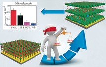
A simple strain approach was explored to prepare a NiFe‐based ORR/OER electrocatalyst derived from surface‐mounted metal–organic frameworks by rational introduction of functional groups into the organic linker. The catalyst exhibits an excellent OER activity, reaching industrially relevant current densities. As a bifunctional catalyst, it demonstrates a narrow overpotential window of ≈0.69 V in 0.1 m KOH, surpassing reported state‐of‐the‐art systems.
Introduction
The oxygen reduction reaction (ORR) and oxygen evolution reaction (OER) play a crucial role in renewable energy provision schemes, which are relevant for e.g., metal‐air batteries, fuel cells and electrolyzers.1 Many efforts have been made to develop efficient bifunctional ORR/OER catalysts, which are typically based on precious metal oxides, [2] perovskites3 and non‐noble metal oxides.4 Among a large number of state‐of‐the‐art electrode materials capable to efficiently catalyze both reactions, metal–organic frameworks (MOFs) and their derivatives have attracted considerable attention due to their tunable lattice structures, porosity and well‐defined compositions, just to name a few aspects.5
However, the previously reported MOF‐based materials including MOF derived materials typically had a low density of accessible active sites. On the other hand, recent studies have shown that the number of catalytic centers can be increased by exfoliating catalysts into nanosheets,6 through phosphorylation of materials (leading to various hierarchy), by increasing their wettability7 or nanostructuring.8 Such catalysts are typically utilized as microcrystalline powders drop‐casted onto electrodes by adding hydrophilic binders. However, the latter multi‐component mixtures can permanently shield most active sites of oxide‐based materials and therefore are rarely used in industrial applications. Moreover, these catalysts show a large bifunctional ORR/OER overpotential window (ΔE ORR‐OER), defined as the difference between the potential required for an OER current density of 10 mA cm−2 and the ORR “half‐wave” potential.9 A small ΔE ORR‐OER is a key requirement for a high efficiency of the above‐mentioned energy provision devices.
According to the well‐known Sabatier principle, a catalyst should bind reaction intermediates neither too strong nor too weak.10 For multi‐electron transfer reactions such as the ORR and OER, the ΔE ORR‐OER value is limited by the so‐called scaling relations related to the binding energies of the reaction intermediates such as *O, *OH and *OOH (*designates the adsorbed state).10b The scaling relations account for the fact that changing the binding energy of one intermediate influences also the binding strength of other adsorbed intermediates at the catalytic center. Thus, designing an effective bifunctional catalyst with a small overpotential for both the ORR and the OER is a big challenge.
Recently, we have demonstrated that a binder‐free NiCo‐based hydroxide film derived from surface‐mounted metal–organic frameworks (SURMOFs) can exhibit superior OER performance compared to the existing NiCo‐ and NiFe‐ based electrocatalysts. To be specific, an anodic current density >200 mA cm−2 was achieved at an overpotential of ≈250 mV.11 Recent findings show that adjusting the lattice‐strain in catalysts can enhance their catalytic activity.12 The intercalation of ions into electrode materials such as graphite or transition‐metal dichalcogenides has proven to be an accessible way to introduce a controllable level of strain and therefore tune the catalytic activity of certain catalysts.13 The positive impact of the strain on the catalytic activity of certain materials can be traced back to a shift of the binding energy of adsorbates towards the optimum.14
Inspired by these findings, we developed an electrocatalyst strain modulation approach to design highly active bifunctional ORR/OER electrocatalysts based on surface mounted metal–organic frameworks (SURMOFs).
In this work, a NiFe‐BDC SURMOF (BDC=1,4‐benzenedicarboxylic acid) was synthesized and transformed into a NiFe‐based oxy‐hydroxide thin film, which retains the BDC component (NiFe‐BDC SURMOFD, denoted as 1−H), via a facile one‐step alkaline treatment (Figure 1). The electrocatalytic activity towards the OER of 1−H was optimized. Various functional groups such as −Br, −OCH3, and −NH2 were introduced to BDC in order to stimulate defect strain and to tailor the binding energies of the SURMOFDs for an enhanced OER activity.15, 16 Among the prepared electrocatalysts, NiFe‐BDC(NH2) SURMOFD (denoted as 1−NH2) shows particularly high OER activity, with an anodic current density of 200 mA cm−2 at an overpotential of just ≈210 mV. Moreover, 1−NH2 remains stable for more than 120 h at a current density of 500 mA cm−2. The ΔE ORR‐OER was found to be ≈0.69 V, outperforming the state‐of‐the‐art catalysts.
Figure 1.

a) Preparation of NiFe‐BDC (X) SURMOFs (X=NH2, H, OCH3 and Br) by layer‐by‐layer deposition; b) Grazing incidence X‐ray diffraction (GIXRD) of NiFe‐BDC(H) SURMOF; c) Transformation of NiFe‐BDC (X) SURMOFs to NiFe‐BDC (X) SURMOFDs (denoted as 1−X); d) GIXRD of NiFe‐BDC (H) SURMOFD (denoted as 1−H). Surface‐mounted metal–organic frameworks: SURMOFs; surface‐mounted metal–organic frameworks derivatives: SURMOFDs; NiFe‐BDC (NH2) SURMOFD: 1−NH2; NiFe‐BDC(OCH3) SURMOFD: 1−OCH3; NiFe‐BDC(Br) SURMOFD: 1−Br.
Results and Discussion
Adjustment of the Ni/Fe Feeding Ratio and Deposition Cycles of 1–H for the Optimization of the OER Performance
The OER activity of NiFe‐based oxo‐hydroxo compounds typically correlates with the Ni to Fe ratios and deposition cycles.17 Thus, we studied the electrocatalytic activity of 1−H with different Ni/Fe feeding ratios and a different number of deposition cycles. The corresponding NiFe‐BDC SURMOFs were prepared on self‐assembled monolayer modified electrodes by a liquid phase layer‐by‐layer deposition technique (Figure 1 a,b, Table S6 and Figure S1 in the Supporting Information). Afterwards, they were transformed into NiFe‐based oxy‐hydroxides (SURMOFDs) in alkaline electrolytes (Figure 1 c,d and [Eq. (1)]).
| (1) |
Where [xNi2+, (1−x)Fe2+][BDC] is the chemical formula of the defined NiFe‐BDC SURMOF. The one‐step post‐treatment of NiFe‐BDC with KOH leads to the formation of bimetallic NiFe‐hybrid hydroxide thin films with some retention of BDC and intercalation of potassium cations and water.
In order to minimize effects of electrolyte resistances, to suppress the formation of macro oxygen bubbles, and to study the intrinsic activity of our catalysts, microelectrodes have been utilized as substrates for the SURMOFDs. As shown in Figure S2, 1−H with a Ni/Fe feeding ratio of 6:1 shows the highest electrocatalytic activity towards OER. X‐ray photoelectron spectroscopy (XPS) analysis reveals an actual Ni/Fe ratio of 3:1, which is in agreement with the optimum Ni/Fe ratio reported in the literature (Figure S3, Table S1).18 It is also well‐known that the activity of a catalyst is associated with the mass loading.19 However, the determination of the mass loading would be inaccurate due to the small geometric size of the microelectrode and the low loading of 1−H (nanograms level). Therefore, we focused on optimizing the number of deposition cycles of 1−H to achieve the highest catalytic OER activity normalized to the electrode geometric surface area. Although the exact quantitative determination of the mass at the level of nanograms on the microelectrode is not possible, the number of deposition cycles can be correlated to the mass loading on the electrode (Figure S1). Upon increasing the number of deposition cycles of 1−H from 10 to 30, the anodic current density at the overpotential of 300 mV (jη=300 mV) rises from 0.09 to 1.43 A cm−2 (Figure S4a). This enhancement of activity with the number of deposition cycles is attributed to a higher catalyst mass loading. However, further increasing the number of deposition cycles of 1−H from 30 to 60 leads to a decrease of jη=300 mV to 1.16 A cm−2. The reduced activity can probably be explained by an increasing electric resistance of the electrocatalyst film, hindering efficient charge transfer and further impeding the OER process at a certain amount of deposition cycles. Herein, a film with an optimum electrocatalytic activity is reached after 30 deposition cycles. In a word, we found that preparation of a NiFe‐BDC SURMOF with a Ni/Fe feeding ratio of 6:1 and 30 deposition cycles leads to a SURMOFD with an optimum OER activity. Thus, this deposition protocol served as a starting point for the following modifications.
Structural, Morphological and Compositional Studies of 1–H
Before further probing the electrochemical properties of 1−H, the structure, morphology and composition of NiFe‐BDC SURMOF and 1−H were investigated. As shown in Figure 1 b, the grazing incidence X‐ray diffraction (GIXRD) patterns of NiFe‐BDC SURMOF match well with the ones of 2D nanosheet NiCo‐BDC MOF.6b The only significant peak at 8.95° reflects the preferred [200]‐orientation growth. After immersing the SURMOF into 0.1 m aqueous KOH, it selectively transforms into SURMOFD 1−H. Figure 1 d displays the XRD patterns of 1−H, which we assign to a NiFe‐LDH (LDH, layer double hydroxide) with intercalated BDC according to equation 1. X‐ray photoelectron spectroscopy (XPS) data further confirm this assignment; the O 1s binding energy is shifted from 531.4 eV to 531.0 eV, the Ni 2p3/2 binding energy from 855.9 eV to 855.5 eV and the Fe 2p3/2 peak is shifted from 712.2 eV to 711.5 eV (Figure S3, Table S1). Attenuated total reflectance IR (ATR‐IR) spectra show the typical peaks at 1541 cm−1 and 1362 cm−1, which are assigned to the symmetric and asymmetric carboxylate signals of BDC, suggesting that BDC is still present in the 1−H interlayer after KOH treatment (Figure S5).
Scanning electron microscopy (SEM) and atomic force microscopy (AFM) images show that the 1−H exhibits the same homogenous and dense morphology as the NiFe‐BDC SURMOF (Figures 2 a,b and Figures S6a, S6b). Energy‐dispersive X‐ray spectroscopy (EDS) mapping images indicate a homogenous distribution of Ni and Fe in the SURMOF and the corresponding 1−H (Figure S6c–f).9a ToF‐SIMS analysis further confirms that all the elements are homogeneously distributed on the surface (Figure 2 c,d and Figure S7).
Figure 2.

a) SEM and b) AFM image of 1−H. c, d) High‐resolution time of flight secondary ion mass spectrometry (ToF‐SIMS) ion images of 1−H: c) Ni+ signals; d) Fe+ signals. The ToF‐SIMS ion images suggest the homogenous distributions of Ni and Fe.
Electrocatalytic Activity of 1–H Towards the Oxygen Evolution Reaction
To assess the electrocatalytic activity, polarization curves of 1−H were recorded in O2 saturated 0.1 m KOH standard conditions. It can be seen that, at an overpotential of 300 mV, 1−H exhibits a current density of 0.70 A cm−2, which is ≈3 times higher than the one recently reported for NiCo‐BDC SURMOFD (0.26 A cm−2; Figure S8).9a This result suggests that replacing Co with Fe in the respective SURMOFD system can further enhance the electrochemical activity towards OER. This can at least partially be ascribed to the fact that Fe can not only generate more vacancies for Ni due to the Ni–Fe electronic coupling but also enhances the electronic conductivity of the SURMOFD.20 When heating the system, the current density of 1−H increases with temperature, which is beneficial for the application of this material in electrolyzers typically operating at elevated temperatures (Figure S9).
The products of the OER were analyzed by rotating‐ring disk electrode (RRDE) measurements.9a To determine the onset potential of the OER, a constant potential of 0.70 V vs. the reversible hydrogen electrode (RHE) was applied to the Pt ring electrode while the potential of the disc was cycled. As shown in Figure S10a, at a working electrode (WE) potential of 1.45 V vs. RHE, a current at the ring can be observed, indicating the onset of the OER.
To investigate possible side reactions, such as the partial oxidation of H2O to H2O2 (Figure S10b), the potential of the ring was changed to 0.20 V vs. RHE. No current at the ring was observed for WE potentials below 1.45 V vs. RHE, implying a four‐electron process takes place, where no H2O2 is produced at the 1−H surface. At a ring potential of 1.50 V vs. RHE, no ring current was detected in a WE potential range of 0.90 to 1.65 V vs. RHE (Figure S11). These results further confirm the four‐electron transfer process for the OER.21
Durability of a catalyst is a crucial parameter for the practical application of electrocatalysts. A long‐term stability test of 1−H was performed by chronopotentiometry response experiments. As shown in Figure S12, while the current density was kept at 500 mA cm−2, the potential remained stable at ≈1.54 V vs. RHE for more than 120 h, endorsing good long‐term robustness of the 1−H catalyst. The PXRD pattern shows that 1−H changed to amorphous NiFe‐LDH after the long term OER test (Figure S13a). The decrease of the crystallinity can be ascribed to some leaching of BDC and the intercalation of potassium ions during the long‐term stability test (Figure S13b and Figure S7). However, crystallinity is not a significant factor in OER activity.22 The morphology of 1−H did not show a significant change after the long‐term stability test (Figure S14).
SURMOFDs Based on Functionalized BDC and their Electrocatalytic Activity
BDC(X) modified with various functional groups (X) was used to grow different NiFe‐SURMOFs. These precursors were transformed into SURMOFDs (1−X) (Figure S15) and their catalytic activity towards the OER and ORR was studied. The functional groups are expected to modulate the defect strain of the SURMOFDs. This should allow to tailor the binding strength between the active sites of the SURMOFDs and the OER reaction intermediates, and thus to further improve OER activity.23a To prove this hypothesis, GIXRD, Raman spectroscopy and XPS were used to investigate the degree of lattice distortion and strain of SURMOFDs interlayered with BDC−X (X=NH2, H, OCH3 and Br) (Figure 3).
Figure 3.

Evidences of defect strain in 1−X: a) XRD patterns; b) the corresponding Raman spectra (error bar ±0.5 cm−1); XPS spectra of c) Ni 2p; and d) Fe 2p (error bar: ±0.2 eV); band gap energy of the 1−X calculated from the UV/Vis diffuse reflectance spectra: e) 1−NH2; f) 1−H; g) 1−OCH3; h) 1−Br (error bar: ±0.01 eV). The films were prepared by 30 deposition cycles, using a precursor Ni/Fe feeding ratio of 6:1.
As shown in Figure 3 a, the GIXRD peaks at ≈11.30° and ≈22.15° are shifted from 1−Br over 1−H, 1−OCH3 and 1−NH2. The shift of the peaks is probably ascribed to the introduction of different functional groups in BDC and strain effects (Table S2). To confirm the existence of the strain effect, the Williamson–Hall (W–H) equation was used to estimate the degree of strain in SURMOFDs.23a According to the W–H equation, a change of defect strain from 1−Br over 1−OCH3 and 1−H to 1−NH2 can be assumed (Figure S16, Table S3).23 The change of strain could also induce material phonon softening and thus further result in a red shift of Raman spectra.24 The tensile strain (phonon softening) of the materials is supposed to improve the electrocatalytic activities of 1−X.23c, 24c As shown in Figure 3 b and Table S4, Raman spectra of 1−X indeed show a slight red shift of the Ni−O bonds (Ni−O, Ni−OH) from 1−Br (peaks at 455 cm−1 and 533 cm−1) to 1−NH2 (corresponding peaks at 449 cm−1 and 527 cm−1). XPS analysis was used to further confirm the different degree of strain among 1−Br, 1−OCH3, 1−H and 1−NH2. As shown in Figure S17, the O 1s peak energies increase in the following order: 1−OCH3 (530.8 eV), 1−H (531.0 eV) and 1−NH2 (531.5 eV), which can be assigned to the adsorbed O−O species.25 This result indicates an increase of the binding strength between the SURMOFD's surface and reaction intermediates upon functionalization from −OCH3 to −H and −NH2.26 The Ni 2p3/2 binding energies of 1−Br are negatively shifted by 0.1 eV and 0.9 eV compared to the corresponding Ni 2p3/2 peaks of 1−OCH3 and 1−NH2, respectively. Conversely, the Fe 2p3/2 peaks of 1−Br are positively shifted by 1.6 eV and 2.4 eV, compared to the corresponding Fe peaks of 1−OCH3 and 1−NH2, respectively (Figure 3 c–d and Table S5). To sum up, the binding energies of Ni 2p3/2 and Fe 2p3/2 are shifted, which suggests a change of bond lengths of Ni−O or Fe−O caused by defect strain.27
UV/Vis diffuse reflection spectroscopy shows that the band gap energy of 1−X exhibits a slight but significant red‐shift of 2.44 eV, 2.39 eV, 2.36 eV and 2.34 eV, for 1−Br, 1−OCH3, 1−H and 1−NH2, respectively (Figure 3 e–h and Figure S18). The red‐shift of the band gap energy of 1−X is assigned to the defect strain increasing from 1−Br to 1−OCH3, to 1−H and to 1−NH2. This shifts the d‐band center towards the Fermi level and leads to a less filled anti‐bonding state according to the d‐band theory.28 The partially filled anti‐bonding state is expected to offer more active sites for the adsorption of oxygen species, which are essential for OER.23a, 28
To study the effect of defect strain in SURMOFDs on the OER, the activity of the 1−X samples grown on Pt microelectrode substrates were measured in O2‐saturated 0.1 m aqueous KOH electrolytes. As shown in Figure 4 a and b, 1−NH2 shows the highest anodic current density of ≈0.86 A cm−2 among all tested OER catalysts at an overpotential of 300 mV, followed by 1−H (0.70 A cm−2), 1−OCH3 (0.50 A cm−2) and 1−Br (0.46 A cm−2). The observations correlate with the degree of defect strain, which increases from 1−Br to 1−OCH3 or 1−H and 1−NH2.The OER activities of SURMOFDs are not exactly consistent with the XRD, Raman and XPS of Ni and Fe. The reason is probably ascribed to the synergetic effects of the size and electron affinity of the substitutes.29
Figure 4.

a) Anodic polarization curves of 1−X (supported on a Pt microelectrode, diameter=25 μm), recorded in O2‐saturated 0.1 m KOH at a scan rate of 5 mV s−1. Temperature: 25 °C. All polarization curves are shown without iR drop compensation; b) Comparison of the current density of 1−NH2, 1−H, 1−OCH3 and 1−Br for the OER at 1.53 V vs. RHE (η=300 mV); c) Anodic polarization curves from ORR to OER regime on 1−NH2 (supported on an Au disc electrode, diameter=5 mm) and blank Au electrodes in O2‐saturated 0.1 m KOH at a scan rate of 10 mV s−1 after 85 % iR‐compensation. Temperature: 25 °C. Rotation speed: 1600 rpm; ΔE refer to the difference between the potential required for an OER current density of 10 mA cm−2 and the ORR half‐wave potential; d) polarization curve of 1−NH2 (supported on an Au disc electrode) at various rotational speeds; e) Comparison of bifunctional activities of ORR and OER with literature data: 2: CoZn‐NC‐700,31 3:Co‐N‐CNTs,32 4: Co3O4‐N‐Carbon,33 5: NiCo2S4@g‐C3N4‐CNT,34 6: N‐GCNT/FeCo,35 7: NC@Co‐NGC,36 8: Co@Co3O4/NC,9a 9: Au, 10: Pt/C,9a 11: RuO2,9a 12: IrO2.9a
Moreover, the Tafel slopes were investigated to examine the OER reaction kinetics of 1−X. As shown in Figure S19, the Tafel slopes at η≈0.20 V were determined: to be ≈26 mV dec−1 for 1−NH2, ≈28 mV dec−1 for 1−H, ≈50 mV dec−1 for 1−OCH3, and ≈51 mV dec−1 for 1−Br. The Tafel slope trends of 1−X from −NH2 to −H, −OCH3 and −Br are consistent with the trends observed by XRD, XPS, Raman spectroscopy and UV/Vis. A comparison of the calculated electron affinities of 1−X further supports the importance of the strain approach for enhanced the OER activity. Low electron affinities of intercalated linkers BDC(X) can increase the density of the unoccupied state of transition metals, boost the binding strength between the active sites of the SURMOFDs and the OER reaction intermediates and further enhancing their OER activity.30 As shown in Figure S20, NH2−BDC shows the lowest electron affinity (0.18 eV) and Br−BDC (0.66 eV) shows the largest electron affinity. The results match well with the observed trend; 1−NH2 shows the highest OER activity, while 1−Br shows the lowest OER activity in the whole potential range above 1.45 V vs. RHE.
Besides, due to the high OER activity of 1−NH2, its potential application as a bifunctional ORR/OER catalysts was explored. Remarkably, 1−NH2 shows a ΔE of ≈0.69 V, outperforming typical benchmark catalysts (Figure 4 c, Figure 4 e and Table S7). In case of the ORR, the number of electrons transferred by 1−NH2 was calculated using the Koutecký–Levich (KL) equation. According to the slopes of the KL plots (Figure 4 d and Figure S21), the number of electrons transferred per O2 molecule in the ORR was calculated to be 3.88, suggesting a predominantly four‐electron reduction pathway. These results conclusively verify the capability of 1−NH2 to be a good bifunctional ORR/OER catalyst.
Conclusion
In summary, we developed a highly active NiFe‐based bifunctional ORR/OER electrocatalyst using a simple layer‐by‐layer deposition approach based on the strain modulation concept. The electrode material was derived from well‐defined surface‐mounted metal–organic frameworks and exhibits a high density of electroactive surface sites. We assume that the binding strength between the reaction intermediates and the catalytically active centers can be experimentally tuned by introducing precursor functional group such as −Br, −OCH3, and −NH2 into the organic linker. These functional groups induce strain, which allows to optimize the interaction of reaction intermediates with the surface of the catalyst and further improves the OER activity. Despite partial leaching of the BDC linker during the OER process, the catalyst still shows remarkable activity after more than 120 h of operation. The prepared SURMOFD catalyst shows a unique bifunctional ORR/OER performance, while the mass loading of the catalyst thin film is about two orders of magnitude lower than the loading of other state‐of‐the‐art bifunctional catalysts reported in the literature. Our discoveries show a simple and effective way to tailor the binding strength between reaction intermediates and active sites. This advancement complements the benefits of the well‐controlled deposition of MOF films with the properties of mixed metal oxides/hydroxides and functionalized organic linkers, which altogether act as a versatile platform for the synthesis of active electrocatalyst structures.
Conflict of interest
The authors declare no conflict of interest.
Supporting information
As a service to our authors and readers, this journal provides supporting information supplied by the authors. Such materials are peer reviewed and may be re‐organized for online delivery, but are not copy‐edited or typeset. Technical support issues arising from supporting information (other than missing files) should be addressed to the authors.
Supplementary
Acknowledgements
W.J.L. is grateful for the support of an Alexander von Humboldt Fellowship for Postdoctoral Researchers. W.J.L. is particularly grateful to Prof. Dr. Hubert Gasteiger for offering the facilities in his laboratories (TUM‐TEC). S.X., S.W., S.H., J.F. and A.S.B. are grateful for the financial support from Deutsche Forschungsgemeinschaft (DFG, German Research Foundation) under Germany's excellence cluster “e‐conversion” (BA 5795/4‐1 and BA 5795/3‐1) and financial support from TUM IGSSE (project 11.01). S.X. and S.H. thank the China Scholarship Council (CSC) for the financial support (201606180040 and 201806140125, respectively). A.L.S. is grateful for a PhD scholarship donated by the German Chemical Industry Fund (FCI). W.J.L. is grateful to Dr. Katia Rodewald, Prof. Bernhard Rieger for the SEM micrographs and Xinyu Jiang, Prof. Müller Buschbaum for providing the UV/Vis diffuse reflection spectroscopic data.
W. Li, S. Xue, S. Watzele, S. Hou, J. Fichtner, A. L. Semrau, L. Zhou, A. Welle, A. S. Bandarenka, R. A. Fischer, Angew. Chem. Int. Ed. 2020, 59, 5837.
Contributor Information
Prof. Liujiang Zhou, Email: liujiang86@gmail.com.
Prof. Aliaksandr S. Bandarenka, Email: bandarenka@ph.tum.de.
Prof. Roland A. Fischer, Email: roland.fischer@tum.de.
References
- 1.
- 1a. Park J., Kwon T., Kim J., Jin H., Kim H. Y., Kim B., Joo S. H., Lee K., Chem. Soc. Rev. 2018, 47, 8173–8202; [DOI] [PubMed] [Google Scholar]
- 1b. Suen N. T., Huang S. F., Quan Q., Zhang N., Xu Y. J., Chen H. M., Chem. Soc. Rev. 2017, 46, 337–365; [DOI] [PubMed] [Google Scholar]
- 1c. Liu G., Li J., Fu J., Jiang G., Lui G., Luo D., Deng Y.-P., Zhang J., Cano Z. P., Yu A. P., Su D., Bai Z., Yang L., Chen Z., Adv. Mater. 2019, 31, 1806761; [DOI] [PubMed] [Google Scholar]
- 1d. Zhang M., de Respinis M., Frei H., Nat. Chem. 2014, 6, 362–367. [DOI] [PubMed] [Google Scholar]
- 2. Nong H. N., Reier T., Oh H.-S., Gliech M., Paciok P., Vu T. H. T., Teschner D., Heggen M., Petkov V., Schlögl R., Jones T., Strasser P., Nat. Catal. 2018, 1, 841–851. [Google Scholar]
- 3. Fabbri E., Nachtegaal M., Binninger T., Cheng X., Kim B. J., Durst J., Bozza F., Graule T., Schäublin R., Wiles L., Pertoso M., Danilovic N., Ayers K. E., Schmidt T. J., Nat. Mater. 2017, 16, 925–934. [DOI] [PubMed] [Google Scholar]
- 4.
- 4a. Han L., Dong S. J., Wang E., Adv. Mater. 2016, 28, 9266–9291; [DOI] [PubMed] [Google Scholar]
- 4b. Kim J. S., Kim B., Kim H., Kang K., Adv. Energy Mater. 2018, 8, 1702774; [Google Scholar]
- 4c. Miner E. M., Fukushima T., Sheberla D., Sun L., Surendranath Y., Dincă M., Nat. Commun. 2016, 7, 1092. [DOI] [PMC free article] [PubMed] [Google Scholar]
- 5.
- 5a. Dang S., Zhu Q.-L., Xu Q., Nat. Rev. Mater. 2017, 2, 17075–17088; [Google Scholar]
- 5b. Shi Q. R., Fu S. F., Zhu C. Z., Song J. H., Du D., Lin Y. H., Mater. Horiz. 2019, 6, 684–702; [Google Scholar]
- 5c. Aiyappa H. B., Masa J., Andronescu C., Muhler M., Fischer R. A., Schuhmann W., Small Methods 2019, 3, 1800415. [Google Scholar]
- 6.
- 6a. Jayaramulu K., Masa J., Morales D. M., Tomanec O., Ranc V., Petr M., Wilde P., Chen Y.-T., Zboril R., Schuhmann W., Fischer R. A., Adv. Sci. 2018, 5, 1801029; [DOI] [PMC free article] [PubMed] [Google Scholar]
- 6b. Zhao S., Wang Y., Dong J., He C.-T., Yin H., An P., Zhao K., Zhang X., Gao C., Zhang L., Lv J., Wang J., Zhang J., Khattak A. M., Khan N. A., Wei Z., Zhang J., Liu S., Zhao H., Tang Z., Nat. Energy 2016, 1, 16184–16193. [Google Scholar]
- 7.
- 7a. Li Y. B., Zhao C., ACS Catal. 2017, 7, 2535–2541; [Google Scholar]
- 7b. Jung W. B., Yun G. T., Kim Y., Kim M., Jung H. T., ACS Appl. Mater. Interfaces 2019, 11, 7546–7552. [DOI] [PubMed] [Google Scholar]
- 8.
- 8a. Huan T. N., Rousse G., Zanna S., Lucas I. T., Xu X., Menguy N., Mougel V., Fontecave M., Angew. Chem. Int. Ed. 2017, 56, 4792–4796; [DOI] [PubMed] [Google Scholar]; Angew. Chem. 2017, 129, 4870–4874; [Google Scholar]
- 8b. Ghosh S., Basu R. N., Nanoscale 2018, 10, 11241–11280. [DOI] [PubMed] [Google Scholar]
- 9.
- 9a. Aijaz A., Masa J., Rösler C., Xia W., Weide P., Botz A. J., Fischer R. A., Schuhmann W., Muhler M., Angew. Chem. Int. Ed. 2016, 55, 4087–4091; [DOI] [PubMed] [Google Scholar]; Angew. Chem. 2016, 128, 4155–4160; [Google Scholar]
- 9b. Dresp S., Luo F., Schmack R., Kühl S., Gliech M., Strasser P., Energy Environ. Sci. 2016, 9, 2020–2024. [Google Scholar]
- 10.
- 10a. Chai G. L., Qiu K., Qiao M., Titirici M., Shang C., Guo Z., Energy Environ. Sci. 2017, 10, 1186–1195; [Google Scholar]
- 10b. Rothenberg G., Catalysis: concepts and green applications, Wiley-VCH, Weinheim, 2008, p. 65. [Google Scholar]
- 11. Li W. J., Watzele S., El-Sayed H. A., Liang Y. C., Kieslich G., Bandarenka A. S., Rodewald K., Rieger B., Fischer R. A., J. Am. Chem. Soc. 2019, 141, 5926–5933. [DOI] [PubMed] [Google Scholar]
- 12.
- 12a. Yao Y., Hu S., Chen W., Huang Z., Wei W., Yao T., Liu R., Zang K., Wang X., Wu G., Yuan W., Yuan T., Zhu B., Liu W., Li Z., He D., Xue Z., Wang Y., Zheng X., Dong J., Chang C., Chen Y., Hong X., Luo J., Wei S., Li W., Strasser P., Wu Y., Li Y., Nat. Catal. 2019, 2, 304–312; [Google Scholar]
- 12b. Strasser P., Koh S., Anniyev T., Greeley J., More K., Yu C., Liu Z., Kaya S., Nordlund D., Ogasawara H., Toney M. F., Nilsson A., Nat. Chem. 2010, 2, 454–460. [DOI] [PubMed] [Google Scholar]
- 13. Wang H., Xu S., Tsai C., Li Y., Liu C., Zhao J., Liu Y., Yuan H., Abild-Pedersen F., Prinz F. B., Nørskov J. K., Cui Y., Science 2016, 354, 1031–1036. [DOI] [PubMed] [Google Scholar]
- 14. You B., Tang M. T., Tsai C., Abild-Pedersen F., Zheng X. L., Li H., Adv. Mater. 2019, 31, 1807001. [DOI] [PubMed] [Google Scholar]
- 15.
- 15a. Gong M., Dai H. J., Nano Res. 2015, 8, 23–39; [Google Scholar]
- 15b. Goldsmith Z. K., Harshan A. K., Gerken J. B., Vörös M., Galli G., Stahl S. S., Hammes-Schiffer S., Nat. Chem. 2017, 114, 3050–3055; [DOI] [PMC free article] [PubMed] [Google Scholar]
- 15c. Qiu Z., Tai C. W., Niklasson G. A., Edvinsson T., Energy Environ. Sci. 2019, 12, 572–581; [Google Scholar]
- 15d. Chen J. Y. C., Dang L., Liang H. F., Bi W., Gerken J. B., Jin S., Alp E. E., Stahl S. S., J. Am. Chem. Soc. 2015, 137, 15090–15093; [DOI] [PubMed] [Google Scholar]
- 15e. Friebel D., Louie M. W., Bajdich M., Sanwald K. E., Cai Y., Wise A. M., Cheng M. J., Sokaras D., Weng T. C., Alonso-Mori R., Davis R. C., Bargar J. R., Nørskov J. K., Nilsson A., Bell A. T., J. Am. Chem. Soc. 2015, 137, 1305–1313. [DOI] [PubMed] [Google Scholar]
- 16.
- 16a. Wang L., Stoerzinger K. A., Chang L., Yin X., Li Y., Tang C. S., Jia E., Bowden M. E., Yang Z., Abdelsamie A., You L., Guo R., Chen J., Rusydi A., Wang J., Chambers S. A., Du Y., ACS Appl. Mater. Interfaces 2019, 11, 12941–12947; [DOI] [PubMed] [Google Scholar]
- 16b. Petrie J. R., Mitra C., Jeen H., Choi W. S., Meyer T. L., Reboredo F. A., Freeland J. W., Eres G., Lee H. N., Adv. Funct. Mater. 2016, 26, 1564–1570. [Google Scholar]
- 17.
- 17a. Hunter B. M., Winkler J. R., Gray H. B., Molecules 2018, 23, 903–909; [DOI] [PMC free article] [PubMed] [Google Scholar]
- 17b. Piontek S., Andronescu C., Zaichenko A., Konkena B., Puring K. J., Marler B., Antoni H., Sinev I., Muhler M., Mollenhauer D., Roldan-Cuenya B., Schuhmann W., Apfel U. P., ACS Catal. 2018, 8, 987–996; [Google Scholar]
- 17c. Fayad R., Dhainy J., Ghandour H., Halaoui L., Catal. Sci. Technol. 2017, 7, 3876–3891. [Google Scholar]
- 18.
- 18a. Hunter B. M., Blakemore J. D., Deimund M., Gray H. B., Winkler J. R., Müller A. M., J. Am. Chem. Soc. 2014, 136, 13118–13121; [DOI] [PubMed] [Google Scholar]
- 18b. Zhang C., Shao M., Zhou L., Li Z. H., Xiao K. M., Wei M., ACS Appl. Mater. Interfaces 2016, 8, 33697–33703. [DOI] [PubMed] [Google Scholar]
- 19.
- 19a. Hoang T. T. H., Gewirth A. A., ACS Catal. 2016, 6, 1159–1164; [Google Scholar]
- 19b. Huang J. H., Chen J. T., Yao T., He J. F., Jiang S., Sun Z. H., Liu Q. H., Cheng W. R., Hu F. C., Jiang Y., Pan Z. Y., Wei S. Q., Angew. Chem. Int. Ed. 2015, 54, 8722–8727; [DOI] [PubMed] [Google Scholar]; Angew. Chem. 2015, 127, 8846–8851. [Google Scholar]
- 20.
- 20a. Wang Y., Qiao M., Li Y., Wang S., Small 2018, 14, 18001361; [Google Scholar]
- 20b. Zou S. H., Burke M. S., Kast M. G., Fan J., Danilovic N., Boettcher S. W., Chem. Mater. 2015, 27, 8011–8020. [Google Scholar]
- 21.
- 21a. Hong W. T., Stoerzinger K. A., Lee Y. L., Giordano L., Grimaud A., Johnson A. M., Hwang J., Crumlin E. J., Yang W., Shao-Horn Y., Energy Environ. Sci. 2017, 10, 2190–2200; [Google Scholar]
- 21b. Zhou R., Zheng Y., Jaroniec M., Qiao S. Z., ACS Catal. 2016, 6, 4720–4728. [Google Scholar]
- 22.
- 22a. Ye Y., Zhang N., Liu X., J. Mater. Chem. A 2017, 5, 24208–24216; [Google Scholar]
- 22b. Chemelewski W. D., Lee H. C., Lin J. F., Bard A. J., Mullins C. B., J. Am. Chem. Soc. 2014, 136, 2843–2850; [DOI] [PubMed] [Google Scholar]
- 22c. Liardet L., Hu X. L., ACS Catal. 2018, 8, 644–650. [DOI] [PMC free article] [PubMed] [Google Scholar]
- 23.
- 23a. Mote V. D., Purushotham Y., Dole B. N., J. Theor. Appl. Phys. 2012, 6, 6–13; [Google Scholar]
- 23b. Kibasomba P. M., Dhlamini S., Maaza M., Liu C., Rashad M. M., Rayan D. A., Mwakikunga B. W., Results Phys. 2018, 9, 628–635; [Google Scholar]
- 23c. Zhou D., Wang S., Jia Y., Xiong X., Yang H., Liu S., Tang J., Zhang J., Liu D., Zheng L., Kuang Y., Sun X., Liu B., Angew. Chem. Int. Ed. 2019, 58, 736–740; [DOI] [PubMed] [Google Scholar]; Angew. Chem. 2019, 131, 746–750; [Google Scholar]
- 23d. Temmel S. E., Fabbri E., Pergolesi D., Lippert T., Schmidt T. J., ACS Catal. 2016, 6, 7566–7576; [Google Scholar]
- 23e. Chattot R., Bacq O. L., Beermann V., Kühn S., Asset T., Guétaz L., Renou G., Drnec J., Bordet P., Pasturel A., Eychmüller A., Schmidt T. J., Strasser P., Dubau L., Maillard F., Nat. Mater. 2018, 17, 827–833. [DOI] [PMC free article] [PubMed] [Google Scholar]
- 24.
- 24a. Chan Z. M., Kitchaev D. A., Weker J. N., Schnedermann C., Lim K., Tumas W., Toney M. F., Nocera D. G., Proc. Natl. Acad. Sci. USA 2018, 115, E5261–E5268; [DOI] [PMC free article] [PubMed] [Google Scholar]
- 24b. Sun Y., Cheng H., Gao S., Sun Z., Liu Q., Liu Q., Lei F., Yao T., He J., Wei S., Xie Y., Angew. Chem. Int. Ed. 2012, 51, 8727–8731; [DOI] [PubMed] [Google Scholar]; Angew. Chem. 2012, 124, 8857–8861; [Google Scholar]
- 24c. Tsoukleri G., Parthenios J., Papagelis K., Jalil R., Ferrari A. C., Geim A. K., Novoselov K. S., Galiotis C., Small 2009, 5, 2397–2402. [DOI] [PubMed] [Google Scholar]
- 25. Wang Y., Zhang Y., Liu Z., Xie C., Feng S., Liu D., Shao M., Wang S., Angew. Chem. Int. Ed. 2017, 56, 5867–5871; [DOI] [PubMed] [Google Scholar]; Angew. Chem. 2017, 129, 5961–5965. [Google Scholar]
- 26. Tao H. B., Fang L., Chen J., Yang H. B., Gao J., Miao J., Chen S., Liu B., J. Am. Chem. Soc. 2016, 138, 9978–9985. [DOI] [PubMed] [Google Scholar]
- 27.
- 27a. Cheng W., Zhao X., Su H., Tang F., Che W., Zhang H., Liu Q., Nat. Energy 2019, 4, 115–122; [Google Scholar]
- 27b. Wang Q., Shang L., Zhang X., Zhao Y., Waterhouse G. I. N., Wu L. Z., Tung C. H., Zhang T., Adv. Energy Mater. 2017, 7, 1700467; [Google Scholar]
- 27c. Bagus P. S., Wieckowski A., Freund H., Comput. Theor. Chem. 2012, 987, 22–24; [Google Scholar]
- 27d. Huang C., Zou Y., Ye Y., Ouyang T., Xiao K., Liu Z. Q., Chem. Commun. 2019, 55, 7687–7690. [DOI] [PubMed] [Google Scholar]
- 28.
- 28a. Stoerzinger K. A., Choi W. S., Jeen H., Lee H. N., Shao-Horn Y., J. Phys. Chem. Lett. 2015, 6, 487–492; [DOI] [PubMed] [Google Scholar]
- 28b. Kitchin J. R., Nørskov J. K., Barteau M. A., Chen J. G., J. Phys. Rev. Lett. 2004, 93, 156801–156803; [DOI] [PubMed] [Google Scholar]
- 28c. Mavrikakis M., Hammer B., Nørskov J. K., Phys. Rev. Lett. 1998, 81, 2819–2822. [Google Scholar]
- 29.
- 29a. Zhou D., Cai Z., Bi Y., Tian W., Luo M., Zhang Q., Xie Q., Wang J., Li Y., Kuang Y., Duan X., Bajdich M., Siahrostami S., Sun X., Nano Res. 2018, 11, 1358–1368; [Google Scholar]
- 29b. Xu Y., Hao Y., Zhang G., Lu Z., Han S., Li Y., Sun X., RSC Adv. 2015, 5, 55131–55135; [Google Scholar]
- 29c. Wang Y., Yan D., Hankari S. E., Zou Y., Wang S., Adv. Sci. 2018, 5, 1800064; [DOI] [PMC free article] [PubMed] [Google Scholar]
- 29d. Dong Y. Y., Ma D. D., Wu X. T., Zhu Q. L., Inorg. Chem. Front. 2020, 7, 270-276. 10.1039/C9QI01367A. [DOI] [Google Scholar]
- 30. Yang C., Grimaud A., Catalysts 2017, 7, 149–175. [Google Scholar]
- 31. Chen B., He X., Yin F., Wang H., Liu D., Shi R., Chen J., Yin H., Adv. Funct. Mater. 2017, 27, 1700795. [Google Scholar]
- 32. Wang T., Kou Z., Mu S., Liu J., He D., Amiinu I. S., Meng W., Zhou K., Luo Z., Chaemchuen S., Verpoort F., Adv. Funct. Mater. 2018, 28, 1705048. [Google Scholar]
- 33. Zhu L., Zheng D., Wang Z., Zheng X., Fang P., Zhu J., Yu M., Tong Y., Lu X., Adv. Mater. 2018, 30, 1805268. [DOI] [PubMed] [Google Scholar]
- 34. Han X., Zhang W., Ma X., Zhong C., Zhao N., Hu W., Deng Y., Adv. Mater. 2019, 31, 1808281. [DOI] [PubMed] [Google Scholar]
- 35. Su C., Cheng H., Li W., Liu Z., Li N., Hou Z., Bai F., Zhang H., Ma T., Adv. Energy Mater. 2017, 7, 1602420. [Google Scholar]
- 36. Liu S., Wang Z., Zhou S., Yu F., Yu M., Chiang C., Zhou W., Zhao J., Qiu J., Adv. Mater. 2017, 29, 1700874. [DOI] [PubMed] [Google Scholar]
Associated Data
This section collects any data citations, data availability statements, or supplementary materials included in this article.
Supplementary Materials
As a service to our authors and readers, this journal provides supporting information supplied by the authors. Such materials are peer reviewed and may be re‐organized for online delivery, but are not copy‐edited or typeset. Technical support issues arising from supporting information (other than missing files) should be addressed to the authors.
Supplementary