

Abstract
In heart failure therapy, minimally invasive devices (transcatheter valves, catheter‐based cannulas or pumps) are increasingly used. The interaction with the valve is of special importance as valve damage, backflow, and thrombus formation are known complications. Therefore, the aim of this in vitro study was to characterize the forces acting on different sized transvalvular cannulas at various transvalvular pressures for four different valves. In a pulsatile setup radial and tangential forces on transvalvular cannulas were measured for bioprosthetic, artificial pericardial tissue, fresh, and fixated porcine valves. The cannula position was varied from a central position to the wall in 10° rotational steps for the whole circular range and the use of different cannula diameters (4, 6, and 8 mm) and transvalvular pressures (40‐100 mmHg). Centering forces of four different aortic valve types were identified and the three leaflets were visible in the force distribution. At the mid of the cusps and at the largest deflection the forces were highest (up to 0.8 N) and lowest in the commissures (up to 0.2 N). Whereas a minor influence of the cannula diameter was found, the transvalvular pressure linearly increased the forces but did not alter the force patterns. Centering forces that act on transvalvular cannulas were identified in an in vitro setup for several valves and valve types. Lowest centering forces were found in the commissures and highest forces were found directly at the cusps. At low pressures, low centering forces and an increased cannula movement can be expected.
Keywords: cannula, centering, force, measurement, transvalvular pressure
1. INTRODUCTION
An established therapeutic option for patients with heart failure is the implantation of a ventricular assist device (VAD). Current developments of new VADs aim toward reduced surgical invasiveness by alternative surgical approaches and miniaturized devices.1, 2, 3, 4, 5 Miniaturized pumps might be directly implanted into the cardiac chamber or the aorta and provide circulatory support in heart failure.6, 7, 8, 9, 10 There are different miniaturized short‐term devices already available on the market or under development for temporary support for a few days (eg, <6 days for Impella 5.0/LD11) or extended periods (eg, 14 days for pulmonary circulatory support Impella RP12 or 30 days for Impella 5.511, 12). Several studies confirm the successful application of such devices.13, 14 However, several potential complications were reported, such as increase in aortic regurgitation during cardiac support,15, 16 aortic or mitral valve damage,17, 18 or thrombus formation.19, 20 Transvalvular pumps have even been used in combination with biologic and transcatheter aortic valve replacements.21, 22, 23
These devices typically pump blood through a cannula placed across the functioning aortic valve, also if the pump itself is placed extracorporeally.24, 25 However, miniaturization of VADs allows direct implantation into the cardiac chamber and allows the use of these pumps as conventional VADs with the outflow cannula passing through the aortic valve.6
For transvalvular devices, the interaction with the aortic valve and especially centering in the aortic orifice seems to play an important role. In the centric position, the valve leaflets equally seal against the cannula, whereas an eccentric position of the cannula can push a leaflet to the side of the aorta and result in an increased mechanical load on the leaflets and backflow. If this happens for a longer period of time leaflets might get damaged or cause regurgitation. Further, the flow in the aorta gets altered and thrombi might form and cause thromboembolic events such as stroke.26
Centering of the cannula in the aortic valve during cardiac support is not a static process and several variables influencing this mechanism are unknown. Depending on the heart’s contractility and the amount of support by the pump, the aortic valve may open during systole (partial support). Here one part of the flow is ejected through the orifice between the leaflets by the heart itself and the second part is pumped by the support device in parallel. In this case, the systolic aortic valve opening allows the cannula to move unhindered within the valve orifice with no contact to the aortic cusps.
In a previous study, the interaction of a transvalvular cannula and the aortic valve was investigated in isolated heart experiments using crystalloid fluids.27 In this configuration, when the aortic valve closed, the aortic cusps pushed the cannula toward the aortic center at physiologic aortic pressures. However, below physiologic low aortic pressures (~25 mmHg), the cannula touched the wall and the force applied by the cusps was not sufficient to allow centering with this device.28
The forces acting on the aortic cusps and transvalvular devices are unknown and might affect the design of new pumps or cannulas that allow centering caused by small forces. The aim of this work was to investigate the dynamic interaction of cannulas with functional aortic valves by measuring quantitative forces that act on transvalvular cannulas.
2. MATERIALS AND METHODS
2.1. Setup
A pulsatile test setup was developed to measure forces acting on different cannulas that are positioned through aortic valves at different transvalvular pressures (see Figure 1). Bi‐directional forces were measured in different biologic and artificial valves at different cannula diameters and at varying transvalvular pressures.
Figure 1.

Schematic drawing of the setup with the pulsatile pump and a picture of the cannula placed in the rotatable holder [Color figure can be viewed at http://wileyonlinelibrary.com]
Four different aortic valve types (pericardial (PEV), bioprosthetic (BIV), fresh porcine (FRV), and fixated porcine (FIV); see Table 1) with a comparable inner diameter of around 20 mm were investigated with this setup (see casts of the closed valves in Figure 2A). Each valve was placed in a molded silicone holder (Sortaclear 18, Smooth‐On Inc., Macungie, PA, USA) that prevented paravalvular leakage.
Table 1.
Overview of the four investigated heart valves
| Valve type | Name | Manufacturer | Description | |
|---|---|---|---|---|
| PEV | Pericardial valve | Magna ease aortic | Edwards Life Sciences, Irvine, CA, USA | Stented bovine pericardial bioprosthesis |
| 3300TFX23MM | ||||
| FRV | Fresh porcine valve | No name | In‐house, extracted from the slaughterhouse | Fresh valve taken from the slaughterhouse, mounted according to Ref. [33] |
| BIV | Bioprosthesis | Mosaic ultra | Medtronic Inc. Minneapolis, MN, USA | Stented porcine bioprosthesis |
| 25A05J0154 | ||||
| FIV | Fixated porcine valve | No name | In‐house, extracted from the slaughterhouse | Valve taken from the slaughterhouse, fixated according to Ref. [33] |
Figure 2.

A, Pictures of the investigated aortic valve casts at closed state. B, Force contour plots for the 8 mm cannula at 80 mm Hg; BIV, bioprosthetic valve; FIV, fixated porcine valve; FRV, fresh porcine valve; PEV, pericardial valve [Color figure can be viewed at http://wileyonlinelibrary.com]
The valve holder itself was rotatable in 10° steps to vary the displacement of the cannula relative to the valve. The first deflection was performed along a commissure (if identifiable between the right and the left coronary cusp). A membrane pump and an adjustable pneumatic drive (in‐house development) were connected to the aortic side of the valve to apply controlled pulsatile transvalvular pressure. This led to the dynamic opening and closing of the valve, which was important to generate realistic dynamics. Forces were measured at the closed state of the valves.
Three stainless steel rods acting as cannula dummies with diameters of 4 mm, 6 mm, and 8 mm were inserted straightly from the ventricular side to investigate the influence of cannula diameter.
A two‐axis force transducer (RFS 150xy, nominal load 20 N, Honigmann GmbH, Wuppertal, Germany) was connected to an amplifier (TAM‐D transducer amplifier module, Hugo Sachs GmbH, March, Germany) and calibrated using a precalibrated 10 N Load Cell (Model WMCP‐1000 g‐538, Bose Corp. MN, USA).
A linear motor (Bose LM1 Testbench motor, Bose Corp. Framingham, MA, USA) held the force transducer and the cannula and allowed the precisely controlled eccentric positioning of the cannula dummy.
Pressures were measured using disposable pressure transducers (Edwards TruWave, Edwards Lifesciences, Irvine, CA, USA) also connected to the transducer amplifier module.
Data were recorded with a sampling rate of 1 kHz via a controller board (DS1103 System, dSPACE digital signal processing and control engineering GmbH, Paderborn, Germany) and analyzed using Matlab (The MathWorks Inc, Natick, MA, USA).
2.2. Measurement protocol and data analysis
At the start of each measurement, the cannulas were placed in the geometric center of the valve, which did not necessarily represent the coaptation point of the valves. Then the cannula was displaced by a linear motor in 1 mm steps toward the valve’s wall. Depending on the cannula’s diameter the number of displacement steps without touching the valve’s wall was different (8 mm cannula—5 steps, 6 mm cannula—6 steps, and 4 mm cannula—7 steps). At each deflection step, the diastolic average of 10 beats was evaluated.
The forces acting on the cannula were examined for the four different valve types, with an 8 mm cannula dummy and a transvalvular pressure of 80 mmHg. The pulsatile pump applied the transvalvular pressure for a diastolic time of 600 ms and a heart rate of 60 bpm. In the 400 ms systolic portion of the cardiac cycle, the valves opened by setting small negative pressure at the membrane pump.
Effects of transvalvular pressures were observed by applying 40, 60, 80, and 100 mm Hg to the PEV and the FRV.
After the experiments, casts of the valves were prepared using alginate (Alginat rosa, Omnident Dental‐Handelsgesellschaft mbH, Rodgau, Germany). The valves were placed upside down, to allow a closing of the leaflets, when the alginate was filled into the valves. After curing, the casts were extracted and photographs were taken (see Figure 2A). The area of the cusps was then evaluated with the image analysis software ImageJ.29
3. RESULTS
The measured area of the cusps for each valve is shown in Figure 2A. Total areas of the valves were: PEV: 335 mm2, BIV: 301 mm2, FRV: 291 mm2, and FIV: 285 mm2. Pulsatile radial and tangential forces acting on a cannula dummy for four different aortic valves were evaluated in a pulsatile setup. Results for a transvalvular pressure of 80 mm Hg and an 8 mm cannula dummy are shown in Figure 2B. For visualization purposes, the size of the cannula is included in the images as a white circular area to visualize the geometric relations. Additionally, contour lines mark forces of 0.1 N and 0.2 N and the force direction vectors are included in the image.
For all valves, the structure of the valves with the cusps and commissures was also seen in the force distribution. Overall, higher forces on the cannula were measured at the middle of the cusps and highest displacement. At the center of the cusps, the force direction pointed toward the coaptation point of the cusps. Lowest values were found at the commissures.
For the PEV with exactly equally sized cusps, the forces showed a highly symmetrical force distribution. Most force vectors were pointing to the center of the valve. The forces in the FRV also clearly showed the geometry of the cusps. However, lower forces and a more uneven force distribution was found. At each commissure, at the valvular border, an area with low forces and vectors not pointing toward the center of the valve but into the commissure were identified. In the BIV the cusps were clearly observable in the force distribution with one cusp being more prominent. Higher maximum and absolute forces than for the FRV were seen there. The force directions at the cusps were generally pointing toward the coaptation point and at the commissure toward the coaptation line. The FIV showed force distributions and directions comparable to the BIV with one prominent cusp and similar force direction.
In all valves except the PEV, one of the leaflets showed higher maximum forces. However, a relation to the cusp size was not seen. Further, in the FRV, the BIV, and the FIV the low force area of less than 0.1 N was extended toward the valvular wall in one commissure. In the PEV the low force was considerably smaller and located only near the center.
3.1. Radial forces
The radial forces, in fact, the forces that lead to centering of a transvalvular cannula, are shown in Figure 3 for the four valves and for all rotational positions. Each line represents the radial force at the different cannula displacements. For all four valves, more or less pronounced peak forces were measured at the mid of the leaflets (marked with a vertical line named “leaf”) and a force sink was measured at the commissures (vertical lines named “com”). With increased displacements, these patterns were more profound and the highest centering forces were found at maximum displacements. At the commissures, the influence of the displacement was less pronounced. For the different valves, the effects were similar. The PEV showed highly symmetrical force patterns at all three cusps and commissural positions. For the FRV, the BIV and the FIV, one cusp position was more pronounced than the others. The total maximum forces ranged from 0.40 N in the FRV, 0.56 N for the FIV, 0.75 N in the PEV to 0.78 N in the BIV. The highest difference (more than threefold) between the highest and the lowest peak was found in the BIV.
Figure 3.

Radial forces (forces pointing to the center) over the rotational positions. The diagrams show the values for transvalvular pressures of 80 mm Hg and the 8 mm cannula; BIV, bioprosthetic valve; FIV, fixated porcine valve; FRV, fresh porcine valve; PEV, pericardial valve
In Figure 4 an overall comparison of the mean centering force at the commissural and mid‐leaflet position in the four different tested valves at 80 mm Hg with the 8 mm cannula is shown. Highest forces were measured for the PEV at the leaflets and at the commissures. The BIV, FRV, and FIV were more comparable to each other and showed lower centering forces than the PEV.
Figure 4.

Comparison of mean centering force at the leaflets and commissures of the four different tested valves
3.2. Variation of cannula diameter
To study the influence of the cannula diameter, different sized cannulas (4, 6, and 8 mm) were used in the PEV and FRV. The force contours are shown in Figure 5. With the 4 mm cannula, the force contours show a tristar‐shaped pattern clearly visible in the 0.1 and 0.2 N contour lines. Higher cannula diameter showed an effect on the force pattern shape. For the PEV the 8 mm cannula showed a nearly circular shape of the 0.1 N contour. In the FRV, the influence of the cannula diameter was smaller; however, the contour lines appeared smoother with less inhomogeneity with the largest cannula.
Figure 5.
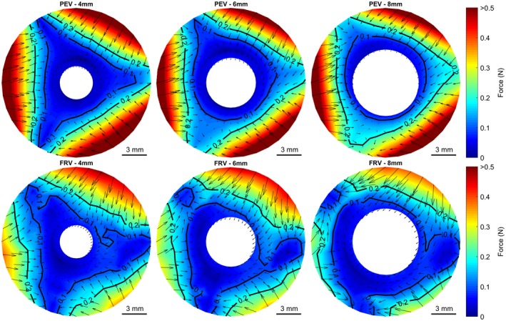
Influence of cannula diameter for the pericardial valve (PEV) and the fresh porcine valve (FRV). Contour plots show the total force and force vectors at a transvalvular pressure of 80 mm Hg with 4, 6, and 8 mm cannula diameter. [Color figure can be viewed at http://wileyonlinelibrary.com]
The mean forces at the commissure and the mid‐cusp position for the different cannula displacements at a transvalvular pressure of 80 mm Hg are shown in Figure 6. At the commissure of the PEV, an increasing cannula diameter showed a tendency to increase the force at higher displacements, whereas in the FRV the forces were generally lower and an effect was not observed. For the mid cusp position, an increasing cannula diameter caused no obvious change in the PEV. However, in the FRV a decrease in the centering force was observed.
Figure 6.

Influence of the different cannula diameters on the total force for the pericardial valve (PEV) and the fresh porcine valve (FRV) at a pressure of 80 mm Hg
3.3. Variation of pressure
The effect of the transvalvular pressure on the cannula forces is shown in Figure 7. A rising transvalvular pressure caused a linear increase in the cannula force for the mid cusp positions. Also at the commissures, a similar relationship was found. The forces in the commissures of the FRV were generally lower and mostly below 0.1 N.
Figure 7.

Influence of transvalvular pressure on the total forces in the pericardial valve (PEV) and fresh porcine valve (FRV) for the 8 mm cannula
4. DISCUSSION
With the miniaturization of cardiac assist devices and the application of minimally invasive catheter‐based support systems, devices implanted across the aortic valve are more widely used. However, the interaction of these devices and cannulas with the aortic valve is mainly unknown. Therefore, in a pulsatile setup radial and tangential forces acting on transvalvular cannulas were evaluated in four different valves. The influence of cannula diameter and transvalvular pressure was measured and differences between valve types were found.
The investigated valves were different in design. Whereas the bioengineered valve PEV consists of bovine pericardial leaflets mounted on a mathematically modeled stent, the other used valve geometries are native from animal sources. Whereas the BIV is a stented porcine bioprosthesis, the two other porcine valves are extracted from pig hearts and mounted stentless in a silicone valve holder.30
The well‐defined symmetric geometry of the PEV was well reflected in the measured cannula forces. The forces at the three cusps and commissures were almost identical and the radial forces pushed the 6 and 8 mm cannula into the center of the valve at all measured positions. Higher displacements and larger cannula diameters increased the centering forces at commissural positions.
The native valves showed higher variations in the centering forces between the single leaflets and different centering forces at the commissures. One influencing factor might be the difference in leaflet size, which could cause this unsymmetrical force distribution, however, the zone of highest centering force was not always seen at the largest leaflet. Further, for the native valves, areas were found where the cannulas did not experience any radial force. This could lead to a cannula that is caught in an eccentric position.
Fresh native aortic valves comprise of very soft leaflets because of the collagen chords which allow free bending in circumferential direction without significant resistance.31 Therefore, the leaflets possibly adapt better to the geometry and curvature of the cannula, which results in reduced radial and tangential forces and therefore a reduced centering force. Further, the commissural suspensions are very fragile, which is not only challenging in aortic valve repair32 but could also be the reason for the low forces and the little influence of the cannula diameter on the centering forces at the commissural positions. Dynamic valve motion is also influenced by the leaflet stiffness, which is also associated with deleterious bending and tissue damage and valve failure.33 The stiffer leaflets and the artificially created commissures of the PEV do not adapt as much as the natural leaflets and therefore create higher radial forces at the commissures and the mid‐leaflet positions. Further, the cannula diameter had no influence on these forces in the PEV. In the FRV, higher cannula diameters led to a reduced centering force, which supports the assumption of the geometrical influence of the soft leaflets.
Higher transvalvular pressures caused higher centering forces with linear behavior at the mid‐leaflet position. For the commissural position, this effect was also found for the PEV, whereas in the FRV no radial forces were seen.
In all valves, the coaptation point of the cusps was found not to be at zero displacement because it was not exactly in the geometric center of the valve.
A transvalvular aortic device, either only a cannula, a catheter, or a pump might be centered at the coaptation point of the valve to reduce the stress on the single leaflets by distributing the closing forces on all of them equally. It is known from transvalvular pacemaker leads that they interact with tricuspid valves and can cause damage or even perforation of the leaflets and the risk for regurgitation might be increased,34 although the lead dimensions are smaller. If a device is constantly touching the aortic wall, this could not only damage the endothelial cell layer, the wall, or the leaflets but altered mechanical forces can also lead to a pro‐inflammatory state within the valve, that may lead to calcifications, sclerosis, and stenosis.35 The forces that can lead to centering of comparable larger cannulas were identified and seem to depend on the stiffness of the leaflets. By using soft and easily bendable cannulas centering might be achieved. These effects will become more and more important for devices that are chronically used.
5. LIMITATIONS
There are indications that transvalvular cannulation might lead to regurgitant flows. In the present study, only extraneous backward flows were seen but not quantified. Nonetheless, in the used setup, the cannula position was retained independent of the forces acting on the cannula. A regurgitation measurement would therefore probably not give reliable readings.
We used fresh and fixated aortic valves harvested from the slaughterhouse. It is known that there are some differences in the size distribution of human and porcine aortic leaflets36 and also in the mechanical properties,37 which are small but absolute values should, therefore, be taken with caution. However, the analysis of the basic physical properties of the valves was not within the scope of this work and can be found elsewhere.37, 38, 39 Nevertheless, commercially treated porcine valves are well accepted and implanted in clinics for several years.
Additional aspects like the movement of the cannula because of systolic ejection, cannula movement caused by the cardiac contraction, or aortic motion as well as effects of connected pumps to the cannula (eg, Impella) were not measured in this setup. However, for a specific transvalvular VAD the dynamic interaction and the pressures necessary to center the transvalvular cannula were investigated previously in an isolated heart setup.28 Therefore it might be important to measure the forces for specific configurations and devices separately.
The placement of the valve into a silicone holder might have a negative effect on the dynamics of the leaflets. Therefore a very soft silicone, with a hardness of shore 18A was used which was shown to result in physiologic valve closure and opening dynamics.30 The casts of the valves were produced at low pressure, therefore the measured areas might be slightly underestimated.
6. CONCLUSION
The force distribution on transvalvular cannulas was measured in a pulsatile in vitro test setup. In varying valve geometries, the influence of changing transvalvular pressures and different cannula diameters were investigated. It has been shown that the highest forces were found at the valve leaflets and lowest at the commissures. In native valves with soft and flexible leaflets, a larger cannula diameter leads to slightly reduced centering forces. Higher transvalvular pressures generally increased the centering forces in a linear fashion. A certain centering force was measured in all investigated conditions. However, the mechanical properties of cannulas or devices might be adapted to facilitate centering and therefore avoid negative effects on the valve as a result of an eccentric cannula position.
CONFLICT OF INTEREST
The authors declare that they have no conflicts of interest with the contents of this article.
AUTHOR CONTRIBUTIONS
Concept/design, data collection, data analysis/interpretation, and drafting article: Stoiber and Aigner
Data collection, critical revision of article: Grasl
Data analysis/interpretation: Röhrich
Data analysis/interpretation, critical revision of article: Moscato
Concept/design, critical revision of article, and approval of article: Schima
Stoiber M, Aigner P, Grasl C, Röhrich M, Moscato F, Schima H. Dynamic measurement of centering forces on transvalvular cannulas. Artif Organs. 2020;44:E150–E160. 10.1111/aor.13597
Martin Stoiber and Philipp Aigner are contributed equally to this work.
REFERENCES
- 1. Haberl T, Riebandt J, Mahr S, Laufer G, Rajek A, Schima H, et al. Viennese approach to minimize the invasiveness of ventricular assist device implantation. Eur J Cardiothorac Surg. 2014;46:991–6. [DOI] [PubMed] [Google Scholar]
- 2. Cheung A, Chorpenning K, Tamez D, Shambaugh C, Dierlam AE, Taskin ME, et al. Design concepts and preclinical results of a miniaturized HeartWare platform: the MVAD system. Innovations (Phila). 2015;10:151–6. [DOI] [PMC free article] [PubMed] [Google Scholar]
- 3. Bejko J, Guariento A, Bortolussi G, Tarzia V, Gerosa G, Bottio T. Minimally invasive surgical Jarvik 2000 off‐pump implantation. Multimed Man Cardiothorac Surg. 2015;mmv020. [DOI] [PubMed] [Google Scholar]
- 4. Wood KL, Ayers BC, Sagebin F, Vidula H, Thomas S, Alexis JD, et al. Complete sternal‐sparing HeartMate 3 implantation: a case series of 10 consecutive patients. Ann Thorac Surg. 2019;107:1160–5. [DOI] [PubMed] [Google Scholar]
- 5. Schima H, Zrunek P, Stoiber M, Larose J, Shambaugh C, Tamez D, et al. Extended in vivo evaluation of a miniaturized axial flow pump with a novel inflow cannula for a minimal invasive implantation procedure. J Heart Lung Transplant. 2014;33:422–8. [DOI] [PubMed] [Google Scholar]
- 6. Tamez D, LaRose JA, Shambaugh C, Chorpenning K, Soucy KG, Sobieski MA, et al. Early feasibility testing and engineering development of the transapical approach for the HeartWare MVAD ventricular assist system. ASAIO J. 1992;60:170–7. [DOI] [PMC free article] [PubMed] [Google Scholar]
- 7. Wang D, Zwischenberger JB, Zhou X, Loran D, Topaz S, Nix C, et al. Development of ‘plug and play’ TransApical to aorta VAD. ASAIO J. 2007;1992:171–5. [DOI] [PubMed] [Google Scholar]
- 8. Anderson MB, O’Brien M. Use of the Impella 2.5 Microaxial pump for right ventricular support after insertion of Heartmate II left ventricular assist device. Ann Thorac Surg. 2013;95:e109–10. [DOI] [PubMed] [Google Scholar]
- 9. Lemaire A, Anderson MB, Lee LY, Scholz P, Prendergast T, Goodman A, et al. The impella device for acute mechanical circulatory support in patients in cardiogenic shock. Ann Thorac Surg. 2014;97:133–8. [DOI] [PubMed] [Google Scholar]
- 10. Van Mieghem NM, Daemen J, den Uil C, Dur O, Joziasse L, Maugenest AM, et al. Design and principle of operation of the HeartMate PHP (percutaneous heart pump). EuroIntervention. 2018;13:1662–6. [DOI] [PubMed] [Google Scholar]
- 11. Griffith BP, Anderson MB, Samuels LE, Pae WE Jr, Naka Y, Frazier OH. The RECOVER I: a multicenter prospective study of Impella 5.0/LD for postcardiotomy circulatory support. J Thorac Cardiovasc Surg. 2013;145:548–54. [DOI] [PubMed] [Google Scholar]
- 12. Pieri M, Pappalardo F. Impella RP in the treatment of right ventricular failure: what we know and where we go. J Cardiothorac Vasc Anesth. 2018;32:2339–43. [DOI] [PubMed] [Google Scholar]
- 13. O'Neill WW, Kleiman NS, Moses J, Henriques JPS, Dixon S, Massaro J, et al. A prospective, randomized clinical trial of hemodynamic support with impella 2.5 versus intra‐aortic balloon pump in patients undergoing high‐risk percutaneous coronary intervention. Circulation. 2012;126:1717–27. [DOI] [PubMed] [Google Scholar]
- 14. Tepper S, Masood MF, Baltazar Garcia M, Pisani M, Ewald GA, Lasala JM, et al. Left ventricular unloading by impella device versus surgical vent during extracorporeal life support. Ann Thorac Surg. 2017;104:861–7. [DOI] [PubMed] [Google Scholar]
- 15. Dixon SR, Henriques JP, Mauri L, Sjauw K, Civitello A, Kar B, et al. A prospective feasibility trial investigating the use of the impella 2.5 system in patients undergoing high‐risk percutaneous coronary intervention (The PROTECT I Trial). JACC Cardiovasc Interv. 2009;2:91–6. [DOI] [PubMed] [Google Scholar]
- 16. Dimas VV, Morray BH, Kim DW, Almond CS, Shahanavaz S, Tume SC, et al. A multicenter study of the impella device for mechanical support of the systemic circulation in pediatric and adolescent patients. Catheter Cardiovasc Interv. 2017;90:124–9. [DOI] [PMC free article] [PubMed] [Google Scholar]
- 17. Chandola R, Cusimano R, Osten M, Horlick E. Severe aortic insufficiency secondary to 5L Impella device placement. J Card Surg. 2012;27:400–2. [DOI] [PubMed] [Google Scholar]
- 18. Woods RK. Reality or singular pipe dream? J Thorac Cardiovasc Surg. 2017;153:183. [DOI] [PubMed] [Google Scholar]
- 19. Ranc S, Sibellas F, Green L. Acute intraventricular thrombosis of an impella LP 5.0 device in an ST‐elevated myocardial infarction complicated by cardiogenic shock. J Invasive Cardiol. 2013;25:E1–3. [PubMed] [Google Scholar]
- 20. Mastroianni C, Bouabdallaoui N, Leprince P, Lebreton G. Short‐term mechanical circulatory support with the Impella 5.0 device for cardiogenic shock at La Pitié‐Salpêtrière. Eur Heart J Acute Cardiovasc Care. 2017;6:87–92. [DOI] [PubMed] [Google Scholar]
- 21. Strauch JT, Franke UF, Breuer M, Wippermann J, Wittwer T, Madershahian N, et al. Technical feasibility of Impella Recover 100 microaxial left ventricular assist device placement after biologic aortic valve replacement (21 mm) for postcardiotomy failure. J Thorac Cardiovasc Surg. 2005;130:1715–6. [DOI] [PubMed] [Google Scholar]
- 22. Thomas MP, Altman A, Magovern GJ, Moraca RJ. Insertion of an Abiomed Impella® left ventricular assist device following bioprosthetic aortic valve placement. J Card Surg. 2013;28:469–71. [DOI] [PubMed] [Google Scholar]
- 23. Singh V, Yarkoni A, O’Neill WW. Emergent use of Impella CPTM during transcatheter aortic valve replacement: transaortic access. Catheter Cardiovasc Interv. 2015;86:160–3. [DOI] [PubMed] [Google Scholar]
- 24. Zhou C, Wang D, Ballard‐Croft C, Zhao G, Reda HK, Topaz S, et al. A transapical‐to‐aorta double lumen cannula‐based neonate left ventricular assist device efficiently unloads the left ventricle in neonate lambs. J Thorac Cardiovasc Surg. 2017;153:175–82. [DOI] [PMC free article] [PubMed] [Google Scholar]
- 25. Kalangos A, Murith N, Baldovinos A, Faidutti B. Conversion from routine CPB to centrifugal mechanical assist by transaortic inflow cannulation of the left ventricle. Ann Thorac Surg. 1998;65:1168–70. [DOI] [PubMed] [Google Scholar]
- 26. Jarvik R. Support stent for transvalvular conduit. US patent 2017/0232170 Al. 7, 2017.
- 27. Granegger M, Mahr S, Horvat J, Aigner P, Roehrich M, Stoiber M, et al. Investigation of hemodynamics in the assisted isolated porcine heart. Int J Artif Organs. 2013;36:1–9. [DOI] [PubMed] [Google Scholar]
- 28. Granegger M, Aigner P, Haberl T, Mahr S, Tamez DA, Graham J, et al. Interaction of a transapical miniaturized ventricular assist device with the left ventricle: hemodynamic evaluation and visualization in an isolated heart setup. Artif Organs. 2016;40:1113–20. [DOI] [PubMed] [Google Scholar]
- 29. Schneider CA, Rasband WS, Eliceiri KW. NIH Image to ImageJ: 25 years of image analysis. Nat Meth. 2012;9:671–5. [DOI] [PMC free article] [PubMed] [Google Scholar]
- 30. Schlöglhofer T, Aigner P, Stoiber M, Schima H. Fixation and mounting of porcine aortic valves for use in mock circuits. Int J Artif Organs. 2013;36:738–41. [DOI] [PubMed] [Google Scholar]
- 31. Balachandran K, Sucosky P, Yoganathan AP. Hemodynamics and mechanobiology of aortic valve inflammation and calcification. Int J Inflamm. 2011;15. [DOI] [PMC free article] [PubMed] [Google Scholar]
- 32. de Kerchove L, Glineur D, Poncelet A, Boodhwani M, Rubay J, Dhoore W, et al. Repair of aortic leaflet prolapse: a ten‐year experience. Eur J Cardiothorac Surg. 2008;34:785–91. [DOI] [PubMed] [Google Scholar]
- 33. Sugimoto H, Sacks MS. Effects of leaflet stiffness on in vitro dynamic bioprosthetic heart valve leaflet shape. Cardiovasc Eng Technol. 2013;4:2–15. [DOI] [PMC free article] [PubMed] [Google Scholar]
- 34. Chang JD, Manning WJ, Ebrille E, Zimetbaum PJ. Tricuspid valve dysfunction following pacemaker or cardioverter‐defibrillator implantation. J Am Coll Cardiol. 2017;69:2331–41. [DOI] [PubMed] [Google Scholar]
- 35. Butcher JT, Simmons CA, Warnock JN. Mechanobiology of the aortic heart valve. J Heart Valve Dis. 2008;17:62–73. [PubMed] [Google Scholar]
- 36. Sim EKW, Muskawad S, Lim CS, Yeo JH, Lim KH, Grignani RT, et al. Comparison of human and porcine aortic valves. Clin Anat. 2003;16:193–6. [DOI] [PubMed] [Google Scholar]
- 37. Martin C, Sun W. Biomechanical characterization of aortic valve tissue in humans and common animal models. J Biomed Mater Res A. 2012;100A:1591–9. [DOI] [PMC free article] [PubMed] [Google Scholar]
- 38. Hasan A, Ragaert K, Swieszkowski W, Selimović S, Paul A, Camci‐Unal G, et al. Biomechanical properties of native and tissue engineered heart valve constructs. J Biomech. 2014;47:1949–63. [DOI] [PubMed] [Google Scholar]
- 39. Soares JS, Feaver KR, Zhang W, Kamensky D, Aggarwal A, Sacks MS. Biomechanical behavior of bioprosthetic heart valve heterograft tissues: characterization, simulation, and performance. Cardiovasc Eng Technol. 2016;7:309–51. [DOI] [PMC free article] [PubMed] [Google Scholar]