

Abstract
Conventional robotic surgery employs pinch and power grips for manipulating a master manipulator. As such, the manipulating methods exhibit limitations that are strongly related to the advantages and disadvantages of the gripping type. The context of this paper is focused on the introduction of a combined grip to compensate for such restraints. In particular, this paper proposed the combined‐grip‐handle scheme on a master manipulator, which employs both the pinch and power grips. A pointing experiment applying the master‐slave scheme was conducted with the master manipulator under several manipulating conditions of the combined grip and the conventional gripping types. Results of using the combined grip demonstrated that the positioning operation performed with fewer failures and required shorter time and trajectory. Compared with the conventional gripping types, the proposed combined grip showed better performance on the positioning operation and provided a possibility to perform precise work at lower scale factors.
Keywords: gripping type, handle, manipulating method, master slave system, robotic surgery
1. INTRODUCTION
Robot assistance during surgical operations has shown a dramatic expansion with the legal recognition of robotic surgery in almost every surgical subspecialty in urology, gynecology, cardiothoracic surgery, otolaryngology, and general surgery.1 Many surgical robot systems, including the da Vinci surgical system (Intuitive Surgical Inc.), employ the master‐slave operation scheme.2 Moreover, with the system, surgeons can improve the dexterity and operational precision with three‐dimensional vision, multidegree‐of‐freedom instruments, and scalable motion control and hand‐tremor‐filtering function. In addition, it is known that haptic feedback improves surgical performance by reducing tissue trauma and the number of accidental incursions into the sensitive structures3; as such, various haptic devices have been adopted as master manipulators in various surgical robot systems. For instance, the MiroSurge, developed by the German Aerospace Center, is controlled by sigma.7 (Force Dimension, Inc.), whereas Raven‐II surgical robot system is controlled by Touch (3D Systems, Inc.).4, 5
A high‐positioning accuracy of the tool tip is the most important requirement for surgery. Surgical robots have motion scaling that improves the accuracy of a surgical procedure.6 However, motion scaling with a larger scale factor implies that bigger motion in the master is required for a certain task and that the working range of the slave without an additional adjustment in operation becomes narrower, which consequently leads to useless motion in the master and perpetual adjustments of either the master or the slave during the operation. Considering these elements, the ability to achieve precise operation even at lower scale factors is compulsory in robotic surgery.
Although existing master manipulators and console units for robotic surgery have been designed ergonomically, robotic surgeons were reported to experience physical symptoms or discomfort, with finger fatigue being the most common.7 The manipulating method of mechanical master manipulators for robotic surgery has a significant influence on the aspect of intuitiveness, comfort, precision, and stability in the operation.8 In addition to enabling precise operation, a comfortable manipulating method could potentially benefit both the patient and the surgeon of robotic surgery.
Pinch and power grips are the most well‐known gripping types adopted in the manipulation of a master manipulator. Mostly, a pinch grip concerns precision works. In conventional surgeries, surgeons have worked precisely using their own dexterity based on the pinch grip.9 On the downside, the tension of hand muscles and the surrounding tissues can be more solicited with a pinch grip than with a power grip, the latter being associated with forceful works. More particularly, in the power grip, there is a strong relation observed between the gripping object and the hand, which implies that all movements of the object have to be initiated by the arm.10, 11, 12 There are two representatives of the conventional manipulating methods: one is the method adopting a pinch grip without using a handle, as in the case of the da Vinci surgical system2; the other is the method adopting a power grip using a handle, such as the surgical robot system with the sigma.7 haptic device.4 Although fundamentally, the use of a handle helps reduce the muscle tension during manipulation of the master manipulator, the rigid relation between the position of the fingers and handle limits the precise operation by the finger movement.8 Therefore, there is a trade‐off between the ability of performing the work precisely and comfort in manipulation based on the conventional gripping methods.
This study aims to establish a more effective manipulating method of a master manipulator in a master‐slave operation by compensating the limitations on the precision and comfort of the conventional manipulations. Herein, we propose a combined grip, which integrates both the pinch and power grip schemes. To evaluate this grip method, we perform a pointing experiment, comparing its performance with the conventional gripping types. Particularly, this study aims to clarify the influences of the gripping types on the positioning operation of manipulators and verify the effectiveness of the combined grip in improving the limitations based on the different aspects of the number of failures, time required, and length of trajectory drawn by the slave manipulator, and preference on the gripping type.
2. MATERIALS AND METHODS
2.1. Concept of a combined grip in manipulating a master manipulator
As mentioned above, there are two well‐known gripping types for objects, namely, a pinch grip and a power grip. The pinch grip, as shown in Figure 1A, requires the fingertips of the two or three fingers, including the thumb, whereas the power grip, as shown in Figure 1C, involves the entire hand. Although in both grips the motion of the hand shows some phases at any moment of activity, there are certain activities in which both grips work together. By description, a combined pinch and power grip requires the two or three fingers (including the thumb) to assume a pinch grip posture with the remaining fingers in a power grip posture.12, 13 In terms of daily activities, for instance, when handling an electrical plug with a long cord, we often hold the plug with two or three fingers and support the external loads from the cord with the remaining fingers for comfortable handling of the plug, as shown in Figure 1B.
Figure 1.

Examples of gripping types: A, pinch grip; B, combined grip; C, power grip
In robotic surgery, the representative manipulating methods of the master manipulator conventionally adopt either a pinch grip or a power grip. Thus, the limitations of the two methods are strongly related to the advantages and disadvantages of the gripping types. On such basis, we can expect the combined grip to improve the manipulation performance during robotic surgery, as it can utilize the advantages of both gripping types while simultaneously compensating their disadvantages.
2.2. Evaluation of the adjustable elements for a pinch grip motion on a handle
The conventional manipulating method using a handle employs a power‐grip‐handle in which all movements are initiated by the arm. To realize the combined‐grip‐handle by enabling a pinch grip motion on the handle, we considered adjustable elements for a pinch grip motion in the distance and direction of the fingertips around the holding axis of a power grip motion. As a result, we could expect the pinch grip motion to improve work precision and speed and minimize hand movements initiated by the arm by taking advantage of the finger movement.
We performed a preliminary experiment for concept verification and evaluation of the influence of the elements for a pinch grip motion on a handle, with the gripping conditions of the experimental tool. In the combined‐grip‐handle illustrated in Figure 2A, the distance and direction between the fingertips and holding axis were passively adjustable, using only the miniature linear guide and the bolt/nut (M6), and not actuators. The experimental conditions were designed such that the distance and/or direction between the fingertips and holding axis were either adjustable or fixed during operation, as shown in Table 1.
Figure 2.
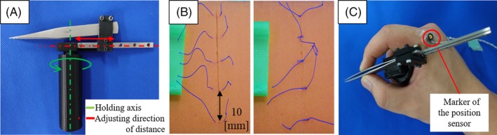
Overview of the preliminary experiment: A, experimental tool; B, experimental task (instrumental tie); C, marker position for measuring trajectory
Table 1.
Gripping conditions of the experimental tool in the preliminary experiment to evaluate the influence of the elements for a pinch grip motion on a handle
| Condition no. | (1) | (2) | (3) | (4) | (5) |
|---|---|---|---|---|---|
| Use of handle | o | o | o | o | |
| Classification of gripping type | Power | Combined | Combined | Combined | Pinch |
| Adjustable element for pinch grip motion | Completely constrained | Distance | Direction | Distance and direction | No constraint |
Ten male participants (age: 25 ± 3) were asked to perform the instrumental tie five times consecutively at 10‐mm intervals, as shown in Figure 2B, with the experimental tool in each gripping condition. All were informed to sufficiently practice in advance. They were divided into two groups: one group performed the experimental task in order from conditions (1) through (5), whereas the other group performed in the reverse order. In the experiment, we obtained the time required to perform the task as the duration from when the thread of the first tie was picked up to the time when the fifth knot was accomplished. We also measured the trajectory of the hand by tracking the marker shown in Figure 2C with the positioning sensor (Optotrak Certus, Northern Digital, Inc.).
Figure 3 shows the experimental results. Note that compared with the completely constrained condition (1), the function of adjusting the distance (2) contributes to the reduction of the movement of the whole hand, and the function of adjusting the direction (3) contributes to the reduction of the time required in the operation. In the condition of using the combined‐grip‐handle adjustable both in the distance and direction (4), the movement and time required were almost equal to the condition of operating the tool directly with the hand (5). On account of these results, we proposed a combined‐grip‐handle for manipulating a master manipulator. Moreover, we presumed that in the combined‐grip‐handle, the position of fingertips for a pinch grip motion should be adjustable in the distance and direction around the holding axis.
Figure 3.
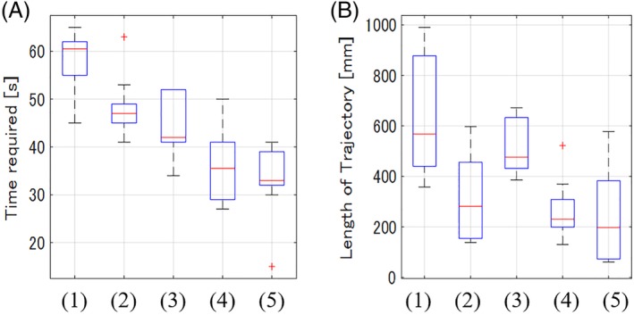
Result of the preliminary experiment: A, time required; B, length of trajectory
2.3. Mechanical design of the combined‐grip‐handle on the master manipulator
The proposed combined‐grip‐handle is adjustable in the distance and direction for a pinch grip motion between the fingertips and holding axis of a power grip motion, according to a miniature linear guide (SSELB6‐70, MISUMI Group, Inc.) and bolt/nut (M6), as shown in Figure 4. During the operation, the master manipulator can be manipulated with the thumb and the index fingertips in a pinch grip motion, whereas the handle is held with the inner three fingers in a power grip motion during operation. Accordingly, the operator can utilize the advantages of the gripping types as selectively as needed, such as the pinch grip motion for precise work and the power grip motion for large movement. Essentially, the fingertips for the pinch grip motion can be positioned in all directions and in the range of 30‐50 mm from the holding axis of the power grip by the finger movement, although the palm is fixed, as shown in Figure 5.
Figure 4.

Gripping part of the master manipulator with the combined‐grip‐handle
Figure 5.

Pinch grip motion in the combined‐grip‐handle when the palm is fixed
The master manipulator herein has a total of 7 degrees‐of‐freedom (7‐DoFs) consisting of three parts: translation part (3‐DoFs), orientation part (3‐DoFs), and gripping part (1‐DoF). In the translation part, we adopted a delta mechanism for high‐positioning accuracy. We mounted a serial gimbal mechanism such that it generates a remote center of motion (RCM) on the top of the translation part, as an orientation part.14 The harmonic drive gears (Harmonic Drive Systems, INC, CSF‐2XH Series) were used as reduction gears, and the backlash of each motor was zero in the translation part. In the orientation part, we did not use reduction gear for high backdrivability. The translation part and the orientation part can be completely separated in control as well as in hardware. We adopted two types of impedance control, namely, force control and motion control, for operating the manipulator with the ability to display haptic information.15, 16 The combined‐grip‐handle is installed on the gripping part of the master manipulator, and the gripping point of the gripping part in the fingertips was consistent with the RCM of the orientation part, as shown in Figure 6.
Figure 6.

Overview of the master manipulator: A, translation part; B, orientation part; C, gripping part; D, all
3. EXPERIMENT AND RESULTS
In general surgical procedures, it is important to move the tool tip of a surgical instrument to the correct position in the appropriate posture, for example, during needle insertion. Based on these requirements of surgery, we evaluated the effectiveness of the combined grip in manipulating the master manipulator on positioning operation in comparison to the conventional gripping types, by carrying a pointing experiment with master‐slave operation under several conditions and conducting a survey regarding the preference of the manipulating conditions.
3.1. Pointing experiment
Figure 7 shows an overview of the master console in the pointing experiment. The head‐mounted‐display in the master console provided an operator with a three‐dimensional vision obtained from the camera in the slave part. The arm rest and the palm rest, which was adjustable in a plane parallel to the ground, were equipped in the master console.
Figure 7.

Overview of the master console
The experimental conditions for manipulating the master manipulator consisted of three variables: a scale factor, or the ratio of the translational movement in the slave to that in the master (2:1, 4:1, 8:1); the condition on fixing the forearm (A, B in Figure 8); and the condition on the gripping type for the master manipulator (a, b, c in Figure 8). Thus, as shown in Table 2, there were six patterns of conditions in combination from Aa to Bc in the three scale factors.
Figure 8.

Experimental conditions for manipulating the master manipulator (A,B, conditions on fixing the forearms; a,b,c, conditions on gripping type)
Table 2.
Experimental conditions for manipulating the master manipulator
| Power grip (a) | Combined grip (b) | Pinch grip (c) | |
|---|---|---|---|
| With arm rest only (A) | Aa | Ab | Ac |
| With arm rest and palm rest (B) | Ba | Bb | Bc |
Variable 1: Condition on fixing the forearm.
A. Forearm fixation with arm rest only.
B. Forearm fixation with arm rest and palm rest.
Variable 2: Condition on the gripping type of the master manipulator.
a. Power grip with the fixed handle.
b. Combined grip with the proposed handle.
c. Pinch grip without a handle.
Figure 9 presents an overview of the pointing experiment. In the slave manipulator shown in Figure 9A, we adopted the delta mechanism (3‐DoFs) in the translation part and gimbal mechanism (3‐DoFs) in the orientation part. As shown in Figure 9B, a 0.6‐mm diameter pin was mounted on the end effector of the slave manipulator and the tip of the pin was consistent with the RCM. We used a harmonic drive gear (Harmonic Drive Systems, INC, CSF‐2XH Series) as a reduction gear in the slave manipulator, and the backlash of each motor was zero. The positioning resolution of the slave manipulator was less than 5 μm.
Figure 9.

Overview of the pointing experiment: A, slave manipulator; B, experimental target; C, tip of slave manipulator
The translation and orientation parts of the master and slave manipulators were separated in control and hardware, and the gripping point of the master manipulator and the tip of the slave manipulator were consistent with the RCMs of each orientation part. In the master‐slave operation, the slave manipulator was operated based on the information of translation and orientation parts obtained from the master manipulator. We control the orientation parts of the master and slave manipulators to maintain consistency with each other, and the translation parts are controlled to follow the equation below.
| (1) |
where is the velocity of the master at Cartesian coordinate; is the velocity of the slave at Cartesian coordinate; and Kscale is the scale factor.
The robotic systems of the master and slave manipulators were controlled by the real‐time OS that used real‐time application interface (RTAI) for Ubuntu 14.04 in the Linux environment, and the two systems communicated using the local area network. The period of control of each robotic system was 1 ms, and the time delay of the master‐slave operation was less than 3 ms.
Figure 9C and Figure 10 present the experimental target in the slave part. The experimental target consisted of the success target, the obstacles to overcome to access the success target, and the light‐emitting diode (LED). We used an M2‐washer as the success target and M1.4‐washers as the obstacles in the experiment. As the inner diameter of the obstacle was 1.5 mm and the diameter of the tip of the slave was 0.6 mm, the success area where the success target can be pointed without contact with the obstacle existed as a circle of 0.9‐mm diameter. When the tip of the slave contacted the success target, the LED in the center of the target turned on. The obstacles were arranged to resemble a square shape with 3‐mm intervals and mounted at a 30° tilt. There were optimal postures of the slave manipulator for each path to access the success target, and the probability of contacting the obstacles increased when the posture was incorrect with respect to the optimal posture.
Figure 10.

Experimental target in the pointing experiment
In the master‐slave operation, the 15 participants (12 males, 3 females, age: 25 ± 3) were instructed to manipulate the master manipulator and to point the success target of the experimental target with the tip of the slave manipulator while avoiding the obstacles. The contact made by the participants with the success target was confirmed by the light of the LED, the participants could proceed to the next step. The order of pointing target in Figure 9C was in the order of ① to ④ twice in a row and finally ① (9 times in total) with each manipulating condition at a certain scale factor. All participants practiced the experimental tasks enough in advance. Moreover, to reduce the possibility of the influence of the learning curve in the repeated pattern on the experimental results, they were divided into two groups: one group performed the experimental task in order from conditions (Aa) to (Bc), and the other group performed in the reverse order at each scale factor. After the participants have completed, the experimental tasks in all manipulating conditions at each scale factor, they were instructed to give a score in the range of 1‐6, according to the preference rank of the manipulating conditions. The most preferred condition received 6 points, and the least preferred condition received 1 point. The experiment was conducted in accordance with the standard ethical practices and was approved by the ethics committee for human experiments of the Tokyo Institute of Technology.
We evaluated the effectiveness of the gripping type in terms of the failure numbers, the time required to complete the tasks, and the length of trajectory drawn by the slave manipulator in the pointing experiment. In this experiment, the contacting information between the tip of the slave manipulator and the target was detected as the electrical signals. Figure 11 presents the conditions of the measurement for the failure numbers and time required. The number of failures was counted as the number of contacts between the slave tip and the obstacles during the operation, whereas the time required was obtained from the time duration between the time of pointing ① in the first cycle (start) to pointing final ① (finish) based on the signals between the slave tip and the success target. The length of trajectory was calculated from the translational position information of the slave manipulator, as shown in Figure 12.
Figure 11.

Measurement of the contacting information between the tip of the slave manipulator and the experimental target in the pointing experiment (one participant, 4:1, Ab)
Figure 12.

Measurement of the positional information in the pointing experiment (one participant, 4:1, Ab)
3.2. Experimental results of the pointing experiment
Figures 13, 14, 15 present the experimental results of the number of failures, the time required, and the length of the trajectory drawn by the slave manipulator, respectively. We can see the results exhibiting a decreasing trend with an increase in the scale factor. Figure 16 shows the averaged preference scores of the manipulating conditions, as given by the participants on each scale factor. The use of the palm rest had a positive influence on the results and the preferences in the case that the scale factor was 2:1, that is, the required movement in the master was small. However, the use of the palm rest had a negative influence in some conditions at 4:1 and all conditions at 8:1, that is, the required movement in the master was large.
Figure 13.

Result of the pointing experiment (number of failures)
Figure 14.

Result of the pointing experiment (time required)
Figure 15.

Result of the pointing experiment (length of trajectory)
Figure 16.

Preference scores of the manipulating conditions in the pointing experiment
The analysis of the results based on the gripping types is presented in the subsequent texts. To determine the statistical differences of the hypothesis that the positioning operation is accomplished with less (shorter) failures (time required, length of trajectory) in the case of using the combined grip compared with the conventional grips, we considered the P‐value of less than 0.05 (one tailed) as significant.
3.2.1. Number of failures
Under the same condition on each scale factor and the forearm fixation, the condition of using the combined grip (b) recorded the least failures, whereas the condition of using the power grip (a) recorded the highest failure at 2:1 and 4:1. At 8:1, the condition of using the pinch grip (c) recorded the highest number of failures.
Tables 3 present the results of the significance test on the number of failures. Based on the results, in the case of using the arm rest only (A), we found statistically significant differences between the condition of using the combined grip (b) and that of using the conventional grips (a, c), except the condition of using the pinch grip (c) at 2:1. In the case of using the arm rest and palm rest (B), there were statistically significant differences in the conditions of using the conventional grips (a, c) at 2:1 and the that of using the power grip (a) at 4:1. However, in the conditions at 8:1 and the condition of using the pinch grip at 4:1, we found no statistically significant differences.
Table 3.
P value resulting from the significance test (one tailed) for the number of failures in the pointing experiment
| Scale factor | 2 | 4 | 8 | P < .05 | |||
|---|---|---|---|---|---|---|---|
| Variable | Aa | Ac | Aa | Ac | Aa | Ac | |
| P value (vs Ab) | .0115 | .0751 | .0009 | .0270 | .0343 | .0016 | |
| Variable | Ba | Bc | Ba | Bc | Ba | Bc | |
| P value (vs Bb) | .0034 | .0154 | .0185 | .1263 | .2249 | .0716 | |
The bold values present the value less than 0.05
3.2.2. Time required
Under the same condition on each scale factor and the forearm fixation, the condition of using the combined grip (b) recorded the shortest time required, whereas the condition of using the power grip (a) recorded the longest time required at 2:1. At 4:1 and 8:1, the condition of using the pinch grip (c) recorded the longest time required.
Tables 4 present the results of the significance test on the time required. Based on the results, we found statistically significant differences between the condition of using the combined grip (b) and the conditions of using the conventional grips (a, c) at 2:1 and 4:1. At 8:1, there were statistically significant differences in the condition of using the pinch grip (c); however, we found no statistically significant differences between the condition of using the combined grip (b) and that of using the power grip (a).
Table 4.
P value resulting from the significance test (one tailed) for the time required in the pointing experiment
| Scale factor | 2 | 4 | 8 | P < .05 | |||
|---|---|---|---|---|---|---|---|
| Variable | Aa | Ac | Aa | Ac | Aa | Ac | |
| P value (vs Ab) | .0089 | .0167 | .0318 | .0004 | .0597 | .0016 | |
| Variable | Ba | Bc | Ba | Bc | Ba | Bc | |
| P value (vs Bb) | .0175 | .0455 | .0041 | .0128 | .1292 | .0186 | |
The bold values present the value less than 0.05
3.2.3. Length of trajectory
Under the same condition on each scale factor and the forearm fixation, the condition of using the combined grip (b) recorded the overall shortest trajectory, except in the case of using the arm rest only (A) at 8:1; the condition of using the power grip recorded the shortest trajectory. At 2:1 and 4:1, the condition of using the power grip (a) recorded the longest trajectory and at 8:1, the condition of using the pinch grip (c) recorded the longest trajectory.
Tables 5 present the results of the significance test on the length of trajectory. Based on the results, we found statistically significant differences between the condition of using the combined grip (b) and that of using the power grip (a) at 2:1 and 4:1. At 8:1, there were statistically significant differences between the condition of using the combined grip (b) and that of using the pinch grip (c).
Table 5.
P value resulting from the significance test (one tailed) for the length of trajectory in the pointing experiment
| Scale factor | 2 | 4 | 8 | P < .05 | |||
|---|---|---|---|---|---|---|---|
| Variable | Aa | Ac | Aa | Ac | Aa | Ac | |
| P value (vs Ab) | .0062 | .1131 | .0004 | .0899 | .3322 | .0332 | |
| Variable | Ba | Bc | Ba | Bc | Ba | Bc | |
| P value (vs Bb) | .0464 | .3640 | .0352 | .2156 | .1792 | .0365 | |
The bold values present the value less than 0.05
3.2.4. Preference
In the case that the scale factor was 2:1 and 4:1, the gripping types were the dominant elements in the preference score. It was possible to separate the three groups of the preference scores based on the gripping type. The preference scores indicated the order of the combined grip (b), the power grip (a), and the pinch grip (c). At 2:1, the preference scores in the conditions of using the arm and palm rest were recorded higher than that of using the arm rest only. Conversely, at 4:1, the preference scores in the conditions of using the arm rest only were recorded higher than that in the case of using the palm rest additionally.
In the case that the scale factor was 8:1, the use of the palm rest was the dominant element in the preference score. It is possible to separate the upper and lower groups of the preference scores depending on the use of the palm rest. The preference scores in the case of using the arm rest only belonged to the upper group. Although the order of preference scores was primarily determined based on the use of the palm rest, in both groups, the preference scores indicated the order of the combined grip (b), power grip (a), and pinch grip (c).
4. DISCUSSION
4.1.1. Comparison with the conventional manipulating methods
The experimental results showed that a more efficient positioning operation with the master manipulator could be realized by using the combined grip (b) in terms of the number of failures, time required, and length of trajectory. Moreover, the manipulating conditions with the combined grip (b) recorded higher preference scores than those with the conventional gripping types.
The two representatives of the conventional manipulating methods of the master manipulator adopted the pinch grip and the power grip, respectively. In these two methods, an arm rest was equipped in a master console to reduce the fatigue and discomfort experienced by the robotic surgeon, which correspond to conditions (Aa) and (Ac), respectively, in the pointing experiment.
In the case of using the pinch grip, there were no statistically significant differences in the precision in terms of the number of failures and length of trajectory compared with the cases of using the combined grip when the required movement in the master was small. However, when the required movement in the master was large, there were statistically significant differences in the precision in terms of not only the time required but also the number of failures and the length of trajectory with the case of using the combined grip. Furthermore, there was a clear difference in the preference. This result is connected to the limitation of the pinch grip where tension on the hand muscles occurs easily, although an intuitive operation is possible with the finger movement. Moreover, we can assume that the limitation of the pinch grip is compensated by utilizing the advantage of the power grip in the combined grip. Significant differences were observed regarding precision between using the power grip and using the combined grip. The differences were significant in terms of the number of failures, time required, and length of trajectory, particularly when the required movement in the master was small. This result is connected to the limitation of the power grip where it is difficult to achieve precise work by the finger movement. Thus, we can assume that in the combined grip, the limitation of the power grip is compensated by utilizing the advantage of the pinch grip.
4.1.2. Possibility to lower the optimal scale factor
In the pointing experiment, the number of failures, time required, and length of trajectory drawn by the slave manipulator exhibited a decreasing tendency with an overall increase in the scale factor. Based on the experimental results, when using the arm rest only, as shown in Figures 13 and 14, the condition of using the combined grip (Ab) at 4:1 recorded the fewer failures and shorter time required compared with the conditions of using the conventional gripping types (Aa, Ac) at 8:1, whereas the condition of using the combined grip (Ab) at 8:1 recorded the fewer failures and shorter time required. This means that with the combined grip, the positioning operation can be performed successfully at a lower scale factor. Moreover, the ability to perform precise works at lower scale factors is advantageous for a surgery work requiring large movements, by reducing the effort of adjusting the operating range, such as the use of a clutch and the change of scale factor during the operation.
The combined grip demonstrated effectiveness with statistically significant differences at each scale factor compared with the conventional gripping types. However, comparing the experimental results in the case of using the arm rest only at 2:1 and 4:1, as shown in Figures 13, 14, 15, the differences owing to the increase of the scale factor were more noticeable than the differences based on the gripping type in terms of the number of failures, time required, and length of trajectory. Therefore, although the use of the combined grip provided the possibility of performing precise positioning operation at lower scale factors, there was a range of optimal scale factors depending on the work. Therefore, similar to the conventional methods, the best motion scaling for a clinical situation to optimize surgical precision exists, and it is essential to select an adequate scale factor in surgical robot systems even when applying the proposed method.
5. FUTURE WORK
In this study, we proposed and evaluated a combined grip that is adjustable in the distance and direction of the fingertips for the pinch grip motion around the holding axis of the power grip motion in manipulating the master manipulator. However, there are many more variables in manipulation, such as other elements for a pinch grip motion in the handle, which requires additional ergonomic access and experimental studies. Moreover, we passively used a palm rest that is adjustable in a plane parallel to the ground. It is generally known that an arm rest and a palm rest increase precision and lessen muscle fatigue in both the conventional surgery and in the operating haptic device of a surgical robot system.17 Since adjusting the palm rest in the direction perpendicular to the ground is a difficult task, a palm rest that is adjustable in all directions may be necessary to achieve its effect within the operational range.
6. CONCLUSIONS
We can generalize the main findings of this study as follows:
Objectively, we proposed a combined‐grip‐handle that is adjustable in the distance and the direction of the fingertips for a pinch grip motion around the holding axis of a power grip motion during the operation, mainly to compensate for the disadvantages of the conventional gripping types. In the system, the handle was installed on the master manipulator.
We conducted a pointing experiment for the combined grip and the conventional gripping types with the master‐slave operation under several manipulating conditions. The results showed that the condition of using the combined grip recorded fewer failures and required shorter time and length of trajectory drawn by the slave manipulator under the same condition in scale factors and forearm fixation. Moreover, the participants preferred the combined grip over the conventional types.
We verified that the positioning operation could be performed better with the combined grip than with the conventional gripping types. Additionally, with the combined grip, it is possible to perform precise work at lower scale factors.
CONFLICT OF INTEREST
The authors declare no potential conflict of interest.
ETHICS STATEMENT
The investigation does not involve any ethical approval.
Jeong S, Tadano K. Manipulation of a master manipulator with a combined‐grip‐handle of pinch and power grips. Int J Med Robotics Comput Assist Surg. 2020;16:e2065 10.1002/rcs.2065
REFERENCES
- 1. Corcione F, Esposito C, Cuccurullo D, et al. Advantages and limits of robot‐assisted laparoscopic surgery: preliminary experience. Surg Endosc. 2005;19(1):117‐119. [DOI] [PubMed] [Google Scholar]
- 2. Guthart GS, Salisbury JK. The IntuitiveTM telesurgery system: overview and application In: Proceedings of the IEEE International Conference on Robotics and Automation, San Francisco, CA, USA, April 2000; 2000:618‐621. [Google Scholar]
- 3. Wagner CR, Stylopoulos N, Howe RD. The role of force feedback in surgery: analysis of blunt dissection In: Proceedings of the 10th Symposium on Haptic Interfaces for Virtual Environment and Teleoperator Systems, HAPTICS 2002. Washington, DC: IEEE Computer Society; 2002:68‐74. [Google Scholar]
- 4. Tobergte A, Helmer P, Hagn U, et al. The sigma.7 haptic interface for MiroSurge: a new bi‐manual surgical console In: IEEE International Conference on Intelligent Robots and Systems, San Francisco, CA, USA, September 2011; 2011:3023‐3030. [Google Scholar]
- 5. Bhardwaj A, Jain A, Agarwal V. Preoperative planning simulator with haptic feedback for Raven‐II surgical robotics platform In: Proceedings of the 10th INDIACom; 3rd International Conference on Computing for Sustainable Global Development, New Delhi, India, March 2016; 2016:2443‐2448. [Google Scholar]
- 6. Prasad SM, Prasad SM, Maniar HS, Chu C, Schuessler RB, Damiano RJ. Surgical robotics: impact of motion scaling on task performance. J Am Coll Surg. 2004;199(6):863‐868. [DOI] [PubMed] [Google Scholar]
- 7. Lee MR, Lee GI. Does a robotic surgery approach offer optimal ergonomics to gynecologic surgeons? A comprehensive ergonomics survey study in gynecologic robotic surgery. J Gynecol Oncol. 2017;28(5):1‐11. [DOI] [PMC free article] [PubMed] [Google Scholar]
- 8. Santos‐Carreras L, Hagen M, Gassert R, Bleuler H. Survey on surgical instrument handle design: ergonomics and acceptance. Surg Innov. 2012;19(1):50‐59. [DOI] [PubMed] [Google Scholar]
- 9. Nissenbaum M, Meckler R, Acland R. Hand position in microsurgery. J Hand Surg. 1979;4(2):118‐120. [DOI] [PubMed] [Google Scholar]
- 10. Feix T, Romero J, Schmiedmayer HB, Dollar AM, Kragic D. The GRASP taxonomy of human Grasp types. IEEE Trans Human Mach Syst. 2016;46(1):66‐77. [Google Scholar]
- 11. de Monsabert BG, Rossi J, Berton E, Vigouroux L. Comparison of muscle loadings between power and pinch grip tasks. Comput Methods Biomech Biomed Eng. 2012;15(1):159‐161. [DOI] [PubMed] [Google Scholar]
- 12. Landsmeer JM. Power grip and precision handling. Ann Rheum Dis. 1962;21:164‐170. [DOI] [PMC free article] [PubMed] [Google Scholar]
- 13. Napier JR. The prehensile movements of the human hand. J Bone Joint Surg. 1956;902‐913. [DOI] [PubMed] [Google Scholar]
- 14. Tsumaki Y, Naruse H, Nenchev DN, Uchiyama M. Design of a Compact 6‐DOF Haptic Interface, Proceedings of the 1998 IEEE ICRA, Leuven, Belgium, May 1998; 1998:2580‐2585. [Google Scholar]
- 15. Tachi S, Sakaki T, Arai H, Nishizawa S, Pelaez‐Polo JF. Impedance control of a direct‐drive manipulator without using force sensors. Adv Robot. 1991;5(2):183‐205. [Google Scholar]
- 16. Tadano K, Kawashima K. Development of a master–slave system with force‐sensing abilities using pneumatic actuators for laparoscopic surgery. Adv Robot. 2010;24(12):1763‐1783. [Google Scholar]
- 17. Fehlberg MA, Gleeson BT, Leishman LC, Provancher WR. Active Handrest for Precision Manipulation and Ergonomic Support. 2010 IEEE Haptics Symposium, Waltham, MA, March 2010; 2010:489‐496. [Google Scholar]