Abstract
Our lives depend upon a constant supply of clean air to breathe, in the home, city, countryside or at our place of work. Air is also consumed in huge volumes for the production of power. Any particulate matter in this air will affect the efficiency and cleanliness of combustion and reduce the lifetime of engine or turbine parts. The off-gases downstream from combustion present a huge environmental problem, either in the local environment or in terms of their impact regionally or even globally.
This section reviews the techniques and equipment used to purify air.
Keywords: Air filtration, dust collection, pneumatic systems, respiratory air, turbine and engine air intake
3.1. Introduction
Our lives depend upon a constant supply of clean air to breathe, in the home, city, countryside or at our place of work. Exposure to contaminated air, either to long-term low-level industrial pollution or as the result of a one-off incident can affect health for decades to come or, even, cause death.
Air is also consumed in huge volumes for the production of power, either in large static power generators or in vehicles. Any particulate matter in this air (or for that matter in liquid or gaseous fuels) can affect the efficiency and cleanliness of combustion, and, in some cases seriously, reduce the lifetime of engine or turbine parts. The off-gases downstream from combustion, bearing soot particles as well as hazardous or damaging gases, present a huge environmental problem, either in the local environment or in terms of their impact regionally or even globally.
Air and other gases are also used as working or power-transmission mediums in, for example, pneumatic or compressed air systems. Many other processes in industry generate dust which can be harmful for humans, the environment or the products being manufactured. (For example, the paint finish on cars would be rough and speckled if dried paint and other dust particles were not removed from the air, not to mention potential health implications for the painters.)
Finally, recovery of dust as a product can be an important consideration, albeit far less frequently as it is for liquid filtration.
While investment and consumption of media in gas filtration is relatively smaller than that for liquid filtration, at less than one-fourth of the total, by some estimates, it remains an important component of the filtration business, and, considering how vital some applications are to the quality of the air breathed in by people and machines, its qualitative importance is greater still.
This section of the handbook covers all aspects of the filtration of air and other gases: inlets and outlets, hot and cold, working and living spaces, machinery and respiratory. It deals with air as a working medium, as in pneumatic systems, and with the recovery of dust from process and engine exhausts.
As with all forms of filtration, in almost all air and gas filtration applications, the demands, in terms of the fineness of the particles that must be removed by filtration and the amount of particulate matter permitted, are growing. Our understanding of the importance of the quality of the atmospheric environment is growing, and air quality requirements, as well as actual air quality, are generally much higher than they were even 20 years ago (with spectacularly notable exceptions in China and other developing countries). Filtration is the process that is primarily responsible for these improvements. The World Health Organization’s (WHO) current guidelines for air quality1 focus upon:
-
•
particulate matter
-
•
ozone
-
•
nitrogen dioxide
-
•
sulphur dioxide.
Filtration clearly impacts upon the amount of particulate matter (and the cut-off particle size) in air. While it can also influence the other parameters directly or indirectly, this will not be discussed further here. The WHO guidelines for particulate matter are as follows:
PM2.5
-
•
10 μg/m3 annual mean
-
•
25 μg/m3 24 h mean
PM10
-
•
20 μg/m3 annual mean
-
•
50 μg/m3 24 h mean
where PM2.5 and PM10 refer to particles of less than 2.5 and 10 µm, respectively. The organization, tellingly, notes that there is, in theory, no lower limit below which some effect on health will not be seen. It is also noted that particles below 2.5 µm are especially harmful, given their affinity to the structure of our lungs. The European Union produced more specific guidelines, based on either targeted or enforceable levels of individual classes of particles, e.g. lead.2
A significant feature of most gas filtration is the relatively low concentration of contaminants in the inlet air, often coupled with high gas feed flow rates. The function of most gas filters is therefore clarification, and while in most cases the dust will not be treated as a product, an important consideration nevertheless in air and gas filtration is the handling of the resulting dust.
The same fundamental principles, discussed in Section 1, are relevant in air filtration and capture mechanisms, surface versus depth filtration as well as filter cake development, discharge and handling are all important factors.
In contrast to the solid–liquid filtration devices discussed earlier, most air and gas filtration systems are passive installations, generally speaking, either a vessel or even a building, containing the filter media. The media are either static and replaced once performance has dropped, due to clogging or solids loading, or pulsed, so that solid particles are removed, normally with a back-pulse of gas.
As with all filtration systems, the incoming gases may be pre-treated before arriving to challenge a filter, e.g. by cyclones, coalescers or electrostatic precipitators, and the filtration process itself may be composed of various stages, from relatively coarse primary or pre-filters through to final ultra-fine filtration. Decisions made in the course of design of the process itself and the selection of media will involve considerations such as the dust loading, the importance (i.e. value) of the outcome and the balance of cost in terms of capital and operating expenditure.
Figure 3.1 shows typical size ranges of common airborne particulate contaminants.
Figure 3.1.
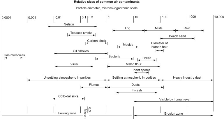
Common air contaminants.
Filters designed for the treatment of air fall broadly into three categories:
-
1.
Primary filters, designed to trap the majority of larger airborne dust particles of 5–10 μm in size, have high dust-holding capacity; these are usually of the dry panel type, pocket or roll filters, capable of working with relatively high airflow velocities.
-
2.
Second-stage filters, with finer media for trapping and retaining finer particles passed by the primary filter, such as particles of 5 μm diameter and smaller; these smaller particles (0.5–5 μm) are the most damaging in terms of staining interior decor in buildings, harmful effects on machinery and in pressure equipment, and so on; these filters may be of the unit or panel, pocket or bag type, with extended depth of filtration; maximum air velocities are generally low, of the order of 0.12 m/s or less.
-
3.
Ultra-fine, or final-stage filters, yielding very high efficiencies (99.95% or better) even with sub-micrometre particles; the chief types here being the high-efficiency particulate air (HEPA) and ultra-low penetration air (ULPA) filters, employing a high-density medium built up from synthetic spun fibres with a sub-micrometre diameter and made in the form of a closely pleated pack; air velocity in this case is limited to about 0.03 m/s.
Electrostatic precipitators (ESPs) also come into this last category because of their capacity for ultra-fine dust filtration, although they can often operate with higher air velocities (depending upon the level and density of the dust).
Attention must be paid to the financial and human consequences of installing inadequate air handling filters which allow fine particles to enter the air handling system. Over a period of time, airborne contaminants will build up in the system to create a potential hazard. Proper system maintenance, including media replacement, is at least as important as correct filter selection and system design. Clogged filters impede airflow and damaged filters contribute to a loss of efficiency, ultimately damaging the air handling and distribution equipment, allowing dust and pollutants to circulate. A multi-stage filter system, such as that shown in Figure 3.2 , should guarantee clean air, as long as it is kept in good order.
Figure 3.2.
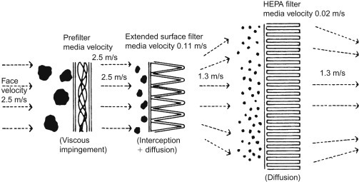
Multi-stage filter system.
3.2. Air Filter Classification
Air filters are classified according to their filtration efficiency, when measured under defined standard conditions. There is no single international standard for such classification, rather national and regional standards, some of which that have been brought together by CEN (Comité Européen des Normalisations) and EUROVENT (European Committee of Air Handling & Refrigerating Equipment Manufacturers), as well as in the United States by ASHRAE (American Society of Heating, Refrigerating and Air-conditioning Engineers).
Two notable standards for the determination of filtration performance of air-cleaning devices are:
-
1.
EN 779:2012 Particulate air filters for general ventilation – Determination of the filtration performance (supersedes EN 779:2002)3, 4
-
2.
ANSI/ASHRAE Standard 52.2-2012 Method of Testing General Ventilation Air-Cleaning Devices for Removal Efficiency by Particle size (supersedes ANSI/ASHRAE Standard 52.2-2007).
Each of these standards (which started from the same point a number of decades ago) incorporates detailed information on the design of the test apparatus, test conditions, sampling methods and the recording and interpretation of test results. Their similarity is demonstrated by the near correlation between figures and illustrations in the standards.
These classifications are a proven method for characterizing air filtration media according to average synthetic dust weight arrestance and average dust spot efficiency. They not only consider simple filtration (i.e. the likelihood of the media capturing a certain particle) but also the tendency of the media to shed particles or allow long-term particle migration through the medium.
As an example, Table 3.1 provides the classification from EN 779:2012, under specific testing conditions of airflow (0.944 m3/s). Filters tested according to these conditions, including the final pressure drop, may be classified according to the second column in the table, i.e. the label on the filter can state, say, G1 or F7, etc. If conditions of flow and pressure deviate, then these conditions should be given in parentheses, e.g. G4 (0.7 m3/s, 200 Pa).
Table 3.1.
Classification of air filters (EN 779:2012)
| Group | Class | Final test pressure drop (Pa) | Average arrestance (Am) of synthetic dust (%) | Average efficiency (Em) of 0.4 µm particles (%) | Minimum efficiency of 0.4 µm particles |
|---|---|---|---|---|---|
| Coarse | G1 | 250 | – | – | |
| G2 | 250 | – | – | ||
| G3 | 250 | – | – | ||
| G4 | 250 | – | – | ||
| Medium | M5 | 450 | – | – | |
| M6 | 450 | – | – | ||
| F7 | 450 | – | 35 | ||
| F8 | 450 | – | 55 | ||
| F9 | 450 | – | 70 |
3.2.1. Types of air filter and other air-cleaning devices
Air filters and other types of air-cleaning equipment can be grouped together as follows:
-
•
Cartridge filters – mainly used as engine intake filters and filters for compressed air systems
-
•
Pad filters – disposable elements made from flat pads of thick fibrous material mounted in frames or panels
-
•
Panel filters – unit filters (including pads) in various media forms, which may be disposable (e.g. by using synthetic fibre or spun glass media), washable (by using polyurethane foam or a similar material), cleanable (e.g. woven metal wire mesh cleaned by immersion in an oil bath) and non-combustible
-
•
Viscous panel filters – employing screens or media wetted with oil, or dry fibre coated with an adhesive gel or coating
-
•
Roll filters – a form of automated panel filters with the filter medium automatically fed through the panel frame from a clean roll on one side to a dusty roll on the other, in the same way that photographic film used to pass through a camera.
-
•
Rotating viscous panel filters – in the form of a continuous curtain loop of metal slats or similar, automatically rotated across the frame, and passing through an oil bath (the oil acting both as a viscous impingement collector and as a cleaning agent)
-
•
Bag or pocket filters – normally arranged as a group across the panel frame and extending through the dividing wall, to provide high-efficiency filtration with high dust retention. The medium is often self-supporting (i.e. it retains the shape of the pocket)
-
•
Particulate air filters (HEPA and ULPA) for final-stage filtering
-
•
ESPs – which may be of the dry type (agglomerators) or have the plates periodically cleaned by water washing (in the dry type, the dust is collected in filter bags or a separate downstream filter)
-
•
Louvres – an aerodynamic type of separator, which also has a capacity for collecting liquid mist particles
-
•
Separators – various types of equipment, working on aerodynamic principles, e.g. cyclones
-
•
Scrubbers – wet dust separators using liquid sprays or other liquid particle trap.
A single air filter element can incorporate a number of the features listed above, e.g. a relatively coarse first stage to remove large particles and protect a subsequent finer stage.
3.3. Pad and Panel Filters
By far the most common ventilation filters are of the panel type, square or rectangular in shape, and of a standard size to be accepted as a push fit into appropriately sized spaces in the dividing wall separating the ventilated area from the outside atmosphere. The simplest form has a flat panel of thick, depth filtration medium (Figure 3.3 ) held in a cardboard or thin metal frame. These pad filters have a relatively low surface area available for filtration.
Figure 3.3.
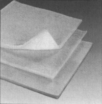
Filter pad media.
More commonly, the filter medium is pleated and/or corrugated held within the same kind of frame as the pad (Figure 3.4 ), but now, because of the pleating, providing a much larger filtration area per frame.
Figure 3.4.
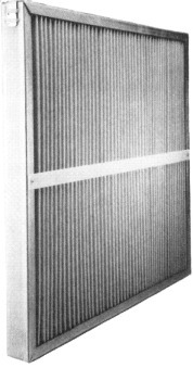
Pleated filter panel.
In some forms of pleated frame, a support is required for the pleats and the overall medium to hold their shape when air flows through and a pressure difference induced. This support may be a coarse mesh or set of bars (horizontal bars to support vertical pleats).
These simple filters can be classified under three headings, depending on whether or not the element is reusable:
-
1.
Disposable, or single use
-
2.
Semi-permanent
-
3.
Permanent
In the case of elements that cannot be cleaned, the complete panel is removed for disposal, and replaced, when the pressure drop across the panel has risen to an unacceptable level or dust has begun to migrate through the medium. Other panels may be designated semi-permanent elements, with cleaning accomplished by removing the panel, laying it face downwards and tapping it gently to remove the dust (or removing dust with a vacuum cleaner). The number of cleaning cycles that can be achieved without damaging the element is limited, hence the type is referred to as a semi-permanent panel.
Permanent panels have stronger elements, which are readily cleanable by removal and washing. These may be dry filters or viscous panel filters, employing metallic elements with or without fibrous interlayers. A particular advantage with viscous panel filters is that they can be designed to have constant or even reducing efficiency characteristics with time, so that the pressure drop will not rise excessively even if cleaning of the filter is delayed or neglected.
Various media, woven and non-woven fabrics, paper, wire mesh and even membranes may be employed for dry panel filters. The most favoured materials are synthetic fibres and glass fibre, in a pad or mat, in multi-layer or pleated form. It possible to coat the media with a viscous agent in order to ensure high dust retention (i.e. to prevent particles becoming re-entrained in the air or migrating through the medium).
3.3.1. Viscous panel filters
Viscous panel filters provide dust retention by the effective impingement of dust on a large area of oily surface. In this respect they can have a superior performance to dry filters (particularly in heavily contaminated atmospheres). Their effectiveness, however, will also rely on adequate particle retention properties to eliminate subsequent re-entrainment of particles as the oil is dried up by collected solids. In practice, the retention properties can be adjusted to give constant efficiency or falling (reducing) efficiency.
This is controlled by the operating characteristics of the viscous panel. If wetting characteristics are adequately maintained, efficiency remains high and substantially constant. In certain circumstances, efficiency may increase, as with conventional dry filters, if the presence of oil on the element assists the formation of a porous bed of solids. If the degree of wetting decreases markedly with build-up of contaminants, the retention properties of the filter will fall, hence its efficiency will also fall.
A simple viscous panel filter comprises one or more layers of wire mesh, usually in crimped or deeply pleated form, or even wire wool held between two layers of mesh. Such types generally tend to have relatively low efficiency and only moderate retention properties. They may also be subject to channelling, where the airflow is directed through individual paths, rather than being distributed over the whole filter area. Better performance is usually achieved by sandwiching a layer of cotton gauze or similar absorbent medium between layers of wire mesh, the gauze both decreasing the average air passage dimension, for increased filtering efficiency, and also increasing the effective mass of oil that can be retained by the panel (i.e. increasing the degree of wetting).
Viscous panel elements incorporating absorbent media layers will normally have constant (or even increasing) efficiency characteristics. Reducing efficiency characteristics are usually given by all-metal construction. Here, efficiency is high as long as the wire surfaces remain tacky, but as the oil is absorbed by accumulating dust, retention capacity falls. This can be advantageous in applications where it is more important that lack of attention to filter cleaning does not generate excessively high back-pressure, than the fact that high filtering efficiency is always maintained. On the other hand, with regular cleaning and rewetting at suitable intervals, the performance of a reducing efficiency filter can remain high in service.
Panel filters constructed from multiple layers of expanded aluminium foil or stainless steel mesh (as shown in Figure 3.5 ) are often used for grease filtration, mist removal and particulate filtration. The units are generally fitted above grills and cookers in commercial and domestic kitchens. The panels have a low initial resistance to airflow and can be installed in high humidity environments, in heating, ventilating and air-conditioning (HVAC) systems, hot air heating units and for the removal of particles from gas flows in industrial processing. For particulate removal applications, each layer of expanded aluminium foil or stainless steel mesh is usually pre-coated with a thixotropic filter coating adhesive.
Figure 3.5.
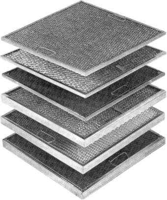
Expanded metal panels.
3.3.2. Activated carbon filters
Activated carbon filters are intended for the removal of fumes and odours from gases, with particulate removal as an incidental activity. Some of the most common applications for the treatment of airborne noxious fumes and gases are in areas such as office blocks, airports, hospitals and theatres. They are also used for the removal of solvent vapours, toxic contaminants or other odours, which can cause offence in a variety of industrial, chemical and commercial environments. For use in air-conditioning applications, the activated carbon is held in a panel, of the same shape and size as a filter panel (Figure 3.6 ), in which the carbon granules are immobilized: bonded at their contact points to form a ‘biscuit’ and encased in a metal frame (which, in turn, is usually located with a number of other filter panels in a housing). These housings can be designed for front or side withdrawal of the panels, with pre-filters to protect the activated carbon panel filters.
Figure 3.6.
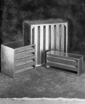
Activated carbon units.
Loosely filled granulated activated carbon is better suited to large deep-bed filters, which often require media depths of up to 1 m. Low depth, loosely filled filters can prove less effective due to their tendency to settle and allow the air to bypass the activated carbon medium or for the activated carbon itself to escape from the filter in the airstream and form into carbon dust. Loosely filled systems will almost always be specified for highly contaminated applications, such as some industrial processes, where deep-bed filters are required.
An important development is the growth of chemically impregnated granulated activated carbon for filtering out or neutralizing specific inorganic molecules such as sulphur dioxide and hydrogen sulphide. Increasing concerns about volatile organic compounds (VOCs) in the working environment are giving carbon filters greater prominence.
3.3.3. Roll filters
Roll filters are normally automatic in operation. The filter medium may be a woven or non-woven synthetic cloth, a glass fibre mat or similar material, possibly backed with mesh or incorporating scrim for additional strength or even carried on a screen. The filter medium may be treated with special wetting fluid to improve dust capacity and filtration efficiency. The cloth roll is simply spooled from top to bottom (Figure 3.7 ), being replaced with a new spool when the whole length has been run through. The part of the roll filter frame that holds the medium is built into the partition wall, and the incoming air is drawn through the medium. Roll filters can be mounted to move the medium vertically (as shown in below) or horizontally.
Figure 3.7.
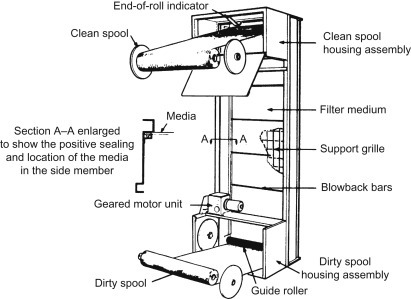
Vertical roll filter.
Various forms of automatic control are possible, the most common being to trigger movement of the filter cloth by a pressure differential set point. This can be preset to operate at a specific differential pressure across the filter medium and start the drive motor moving the cloth to a position when a sufficient new area is exposed to lower the differential pressure back to the original clean figure. A separate inching control is also provided for operating the filter during service, and an end-of-roll indicator to show when the upper spool is running empty.
3.3.4. Bag and pocket filters
Bag and pocket filters have their media in the form of a cylindrically shaped bag or a shaped pocket, closed at one end and open at the other. In principle, dust may be collected on the inside or outside surface, with airflow from inside out or outside in, respectively. Filter bags, for gas filtration, are mainly used in large numbers in baghouses (‘fabric filters’) for the filtration of solid–gas suspensions with a reasonably high solids content (referred to as the dust load).
Although filter pockets can also be used singly, they are much more often found in groups, often many tens of filters, mounted side by side in a rigid front panel, from which they can be withdrawn for disposal.
Pocket filters provide a much higher filter area for a given entry or panel size than an equivalent flat panel. The pockets need to be of somewhat stronger and more rigid construction than the media used in flat panel elements, but may range from impregnated paper, through natural and synthetic non-woven fabrics, to glass cloth, depending on the application involved. For industrial applications, and where fine filtering is required, the pockets are often made from synthetic fibres, or glass wool, protected on both sides by an open mesh scrim. Pockets may be held in a certain shape by internal spacers (e.g. welded fabric tabs or diamonds) to prevent them from being overinflated or blown open.
Multi-layer construction may also be employed using different filter media, e.g. an inner layer of rather more open form for dust retention, an intermediate layer for fine filtration and an even closer outer layer to prevent particle migration.
Pockets are invariably disposable rather than reusable, since back-pulsing is difficult, either individually or the whole panel, so material cost can affect the choice of pocket. Any additional cost, however, is often recoverable, since, in many applications, a pocket filter can provide its own primary and secondary stage filtration, and does not need to be preceded by a coarse primary filter. Many synthetic pocket filters can be disposed of, through incineration.
A pocket filter may be able to perform efficiently from 25% up to 150% of the normal airflow, i.e. it is particularly suitable for variable air volume systems. Pocket filters are available for numerous applications in many configurations, and are capable of maintaining a low pressure drop for several months, or even more than a year.
Pocket filters are particularly suitable for the filtration or fine filtration of atmospheric air intake and/or recirculated air in air handling installations, including ambient air handling as well as process air intake installations. Specific applications include air handling installations for the ventilation of factories, warehouses, department stores, offices, school computer rooms, public buildings, conference or exhibition halls and laboratories, as well as for filtration of the air intake for gas turbines, compressors and engines. They are used for pre-filtration in the air intakes of paint spray booths (note, not in the recirculating air filtration), and before fine or very fine air filters, HEPA or ULPA filters, or activated carbon filters.
The airflow direction in pocket filters is generally into the pocket (into the page in the filters shown in Figure 3.8 ). Dust will accumulate in the pocket and, once the useful lifetime (or performance level) is reached, the units are generally removed and disposed of or, occasionally, washed.
Figure 3.8.
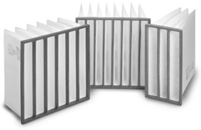
Rigid pocket filters.
In the same way that pleating increased the filtration area versus the frontal area (in the direction of air travel) for panel filters, a similar increase may be achieved for pocket filters by giving the medium a pleated structure. The pleats here cannot typically be as deep as in thicker flat panel elements, but in the form of the V-block, or VCell, element (Figure 3.9 ), the pleats still provide a much larger filtration area and dust capacity (for a similar media) and, therefore, enhanced performance. Such units are found in demanding applications, such as gas turbine air intakes.
Figure 3.9.
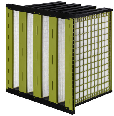
Pleated VCell filter (CLARCOR Industrial Air).
3.3.5. Electrostatic precipitators
The ESP removes dust from air by imposing an electric charge on the dust, in an ionizer, and then passing the suspension between some vertically hanging charged plates (electrodes). Each particle then moves towards the oppositely charged plate and, its path determined by inertia, density and charge, is deposited on to it (Figure 3.10 ).
Figure 3.10.
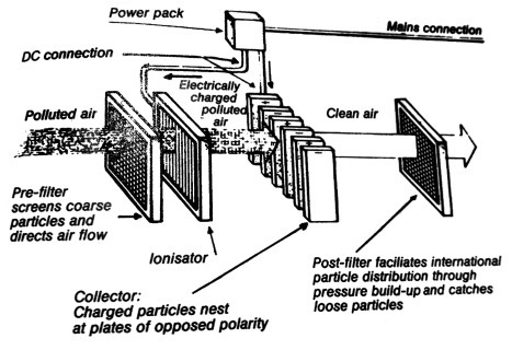
Electrostatic precipitator.
This cannot be considered primarily a filtration process (although it is a large-scale reproduction of the electrostatic deposition particle capture mechanism). Filters are used in an ESP installation – usually a pre-filter to trap large particles, and perhaps a final filter to catch any material not caught by the electrodes. In addition, louvres or a course mesh screens are needed to prevent large trash, leaves, twigs or even birds from entering the installation.
3.3.6. Louvres
Louvres work on the principle of inertial separation, in which air is made to turn a sharp corner and inertia prevents larger or denser particles from making the same turn, continuing on in its original direction. In basic principle, if not execution, this is similar to the cyclone.
Downward facing louvres prevent a significant proportion of rain from passing into air inlets.
Pressure drop across louvres should be minimal compared to the pressure drop across subsequent filtration steps (Figure 3.11 ).
Figure 3.11.
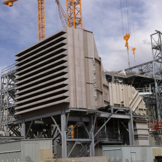
Air intake housing (CLARCOR Industrial Air).
3.3.6.1. Air filter selection
Air filter units should be selected on the basis of the following items:
-
•
level of filtration needed
-
•
filter classification requirements
-
•
cost-effectiveness
-
•
stable collection efficiency
-
•
dust storage capability at a low pressure differential level.
Particular points to be borne in mind during the design of an air filtration system are:
-
•
airflow (should be as uniform as possible across the face of the filter)
-
•
pre-filters should be used ahead of high-efficiency filters to give longer service life
-
•
if the system draws in air from an external wall, then weather louvres and bird screens should be fitted at the intakes
-
•
a differential pressure drop gauge should be fitted across the system to determine when a filter should be serviced
-
•
sufficient access should be provided for servicing the filters
-
•
filters should not be used beyond their specifications
-
•
the recommended final resistance should not be exceeded
-
•
electrostatic air cleaners should not be installed where free moisture can affect them
-
•
the selection of air filters on the basis of lowest cost is not a reliable option in any system design, future needs should be borne in mind and system requirements should be fully discussed with equipment manufacturers.
3.4. Indoor Air Quality
A large proportion of air filters are found in those systems controlling the quality of the air in living accommodation (domestic, commercial and institutional) and in working spaces, especially the growing number of clean room installations for critical assembly processes, such as for medical devices or consumer microelectronics. These are supplemented by vent filters that controlling discharges from working spaces in which potentially hazardous atmospheres are used.
Conveniently grouped under the term ‘air-conditioning’ (or within the acronym HVAC), these filters are the basic means whereby improvement is achieved in the indoor air quality within which humans live or work.
3.4.1. Air handling systems
Air handling systems, in which air filters play a prominent part, can be categorized as follows:
-
•
building installations, from individual houses to large apartment complexes and hotels or office blocks, including HVAC systems
-
•
industrial air filtration, including factory ventilation as well as machinery air intakes and exhausts
-
•
clean rooms, with their very special requirements on air intake and often for venting as well
-
•
moving vehicle ventilation, whether it be a private car, a coach, a train, a passenger airplane or ship.
In order to meet and comply with environmental and local health and safety controls, each air handling installation may require an individual solution. It is important to consider fully the various options and levels of filtration available to meet the performance requirements: over-engineering can be just as expensive in the long run as under-engineering.
3.4.1.1. Building installations
In building services a primary consideration of the filtration system is to achieve the optimum balance between performance, capital cost and running costs. The running costs comprise electricity for running fans, heat exchangers, maintenance labour costs and the replacement of expendable filter media (disposable filter elements) as well as other consumable parts. The trend, too, is towards the adoption of pre-engineered package units for air handling, rather than of piecemeal installation on site. In general, this proves to be more economic and is more readily analysable in terms of likely future material costs: such figures should be available from the manufacturer of the central station unit, including fans, heat exchangers and humidifiers, in addition to the air filtration system.
A further advantage of the package deal is that the panel filters, pocket filters, automatic roll filters and various combinations of filters provided by a systems supplier are designed to match standard dimensions for air handling units. It remains, however, to be decided which types of filter are best suited and most cost-effective for the performance required.
Specifically, a basic question to be answered is whether pre-filters (primary, relatively coarse filters), EN 779 Classes G1–G4, are suitable on their own, or need to be backed up by fine (second-stage) filters, EN 779 Classes M5–M6. Pre-filters normally only remove dust particles down to the order of 5 µm. Applied to centrally heated offices and similar buildings, the amount of finer dust particles remaining in the air after a pre-filter can be considerable, calling for interior cleaning or redecoration at relatively short intervals.
Second-stage filtration, using fine air filter media, to filter down to 1 μm can considerably extend these redecoration intervals, with reduced building maintenance costs, at the expense of increased capital and operating costs for the filter system. Potential savings could be even more significant in large department stores, etc., for reducing both redecorating costs and the amount of shop-soiled goods. Unfortunately, there is no short cut to filter cost savings here, as it is impractical to provide fine filtration at a primary filter stage, primarily because of the lifetime of the media.
3.4.1.2. Pre-filters
For pre-filters the choice of type will normally be between panel filters, pocket filters and automatic roll filters. Efficiencies are relatively low, but with automatic roll filters generally slightly better than panel or pocket types. As a general guideline, panel and pocket filters are almost universally used for building systems handling air flows up to 4000 m3/h, and automatic roll filters with disposable media, or automatic viscous screen filters for larger installations (Figure 3.12 ).
Figure 3.12.
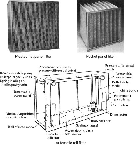
HVAC pre-filters.
3.4.1.3. Fine filters
Where cost-effectiveness or initial capital cost is not a critical factor, flat panel fine filters can be combined with pocket-type filters, to provide second-stage filtration, or electrostatic filters may be used for the retention of even finer particles. If the latter are of the dry type, collection of dust from the electrostatic filters must be by pocket or automatic roll filter. Dry-type electrostatic filters usually combine such dust collectors in an integral unit. Both pocket-type filters and electrostatic filters are particularly suitable for variable air volume systems, where air volumes can vary from 20% to 110% of design value. Other types of filters are less effective for variable volume flow. Variable air volume systems are becoming increasingly prominent because of the energy savings that are possible.
Apart from the effect of variable air volumes on the effectiveness of certain types of filter, other system characteristics may dictate the choice of filter type, particularly as regards flow velocities. In general, the higher the efficiency of a filter, the lower the permissible design flow rate; hence in many cases it may be necessary to downgrade filter performance to accept necessary operating parameters, such as ruling out the possibility of employing a two-stage in-line filter package.
3.4.1.4. HVAC system requirements
A complete HVAC system for a building is required to induct atmospheric air, clean and heat or cool it, and then circulate the treated air throughout the premises. The amount and type of contaminants present in the air will vary widely with the location site of the system, as well as the time of year and particular weather. In rural areas, dust concentration is likely to be of the order of 0.05–0.5 mg/m3 and to comprise mainly soil erosion particles, vegetable matter, seasonal pollens and a minimum of carbonaceous matter. Naturally, during a period with little rain and higher winds, the dust concentration will be higher. In metropolitan areas dust concentration is likely to be 0.1–1 mg/m3, with a high proportion of carbonaceous matter, ash, silicon and other granular products. In industrial areas, the figure can be expected to be the order of 2–5 mg/m3, with a large content of carbonaceous matter, as well as tarry oils and waxes, mineral and chemical dusts, sulphurous gases and acids. In certain parts of the developing world, notably large cities in China powered by coal, dust concentrations can be orders of magnitude higher.
Non-woven media, made from progressively structured thermally and resin-bonded synthetic fibres, the typical choice for this applications has a low pressure drop and a high dirt load efficiency. The material is generally available as cut sheets or pads or in roll form in lengths up to 40 m. Typical application areas include laboratories, hospitals, offices, departmental stores, schools, factories, warehouses, exhibition and conference halls, paint spray plants, clean rooms and computer centres. Additionally, a range of materials with graded density structures has been developed especially for final air filtration applications.
Activated charcoal filter media are used to remove many odours and fumes, such as those caused by cooking foods, cigarette smoke, some corrosive gases, decaying substances, industrial wastes and so on. Activated charcoal is particularly effective against organic odours.
Where ammonia-based odours and fumes are present, synthetic media such as non-woven polyester impregnated with activated carbon or zeolite can be used. These filters have proved useful for removing odours in nurseries or other child care facilities, hospitals and nursing homes, animal facilities, public restrooms and so on.
Filter life tends to vary considerably with these units but, generally, if the filter is cleaned of clogging particles regularly, i.e. rinsed free of dust with plain water or vacuum cleaned, then, depending on usage, the filter could for several months. Air velocity, humidity and temperature all have an influence on the effectiveness of odour-removing filters.
3.4.1.5. Stand-alone air purifiers
Air purifiers or air cleaners are gaining in popularity for use in offices and private homes. These units, which stand alone in a convenient corner of a room, can be effective for the removal of dust, pollen, tobacco smoke and odours. They generally comprise two- or three-stage filtration, using electret filters of disposable woven or felted glass fibre. Typical airflows range from 150 to 2200 m3/h. The units can also be wall or tabletop or ceiling mounted, and provided with variable speed selection.
3.4.1.6. Industrial air filtration
In factories, a dirty atmosphere can produce an unpleasant working environment, reduce operator efficiency, affect health, shorten the life of machines, increase maintenance costs and contaminate products. The problem of air treatment is aggravated by the abnormally high concentration of heavy and/or abrasive contaminants in the industrial atmosphere. Full control may be beyond the scope of conventional HVAC air filtration systems (or be uneconomic to apply). In this case, special dust collecting treatment may need to be applied to specific areas, as discussed later in this section.
Industrial dusts may range in size from 1 mm (1000 μm) down to about 1 μm or even down to 0.1 μm in the case of cupola dust, foundry dust, electric arc furnace dust and paint pigments. Current state-of-the-art surface finishing applications call for superfine air filtration of the air supply side of paint spray plants and downdraught paint booths. An important criterion in this technology is to prevent painted surface-damaging particles 15 μm and larger from migrating downstream after collection in a filter, due to vibration in the system.
When choosing an air filter medium for industrial dusts, it may be preferable to select one that has been tested using a test dust of non-adhesive free-running aluminium oxide particles and proven to have collected this dust without unloading or allowing migration under vibration.
The basic central air treatment plant will have a primary filter at the plant inlet, to protect the air-conditioning units, especially the heat exchanger, a humidifier and the circulating fan. There is then, finally, a second-stage filter to provide finer filtration, sited just before the outlet duct from the plant. The cost of ultra-fine filtration usually prohibits its use for a general factory scheme, it being usually restricted to point-of-use areas, especially clean rooms.
3.4.1.7. HEPA and ULPA filters
Very fine filtration can be provided by individual air inlet filters where flow volumes and flow rates are lower and higher pressure drop is tolerable. Here HEPA filters and ULPA are a suitable solution. The greater resistance to flow of the ultra-fine filter medium can be offset by increasing the filter area as the actual size of the module is rarely critical. Characterization of these filters is described, e.g. in EN 1822:2009 – test methods for EPA/HEPA/ULPA filters.5
As for EN 779 and ASHRAE 52.2, this standard describes in detail the test equipment, method, sample dust, data collection method and the way to present data. The standard is centred on the performance of the filter for the most difficult, or most penetrating particle size (MPPS) (Figure 3.13 ).
Figure 3.13.
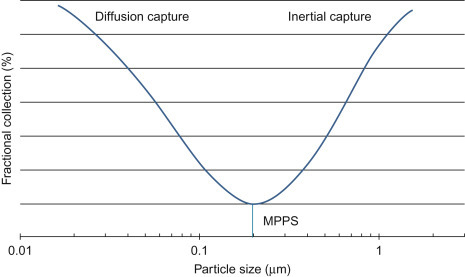
MPPS, in this case around 0.2 µm. Larger particles are captured through inertial (and sieving) mechanisms, while smaller particles are retained by diffusion.
The MPPS is determined using a test on a flat sample of filter media and the measurements at the MPPS then taken using an assembled filter element (incorporating pleats for example).
New classifications have been defined for both types of filter according to EN 1822:2009 and these are given in Table 3.2 EN 1822 classification. The system is based on letters and figures in the same way as for coarse and fine filters according to the EN Classes. The filters are divided into eight classes from H10 to U17, depending on the efficiency of their media at the MPPS and the size of any weaknesses or leaks introduced by fabrication of the finished item.
Table 3.2.
EN 1822 classification
| Integral value |
Local value |
|||
|---|---|---|---|---|
| Filter class | Collection efficiency (%) | Penetration (%) | Collection efficiency (%) | Penetration (%) |
| E10 | 85 | 15 | – | – |
| E11 | 95 | 5 | – | – |
| E12 | 99.5 | 0.5 | – | – |
| H13 | 99.95 | 0.05 | 99.75 | 0.25 |
| H14 | 99.995 | 0.005 | 99.975 | 0.025 |
| U15 | 99.9995 | 0.0005 | 99.9975 | 0.0025 |
| U16 | 99.99995 | 0.00005 | 99.99975 | 0.00025 |
| U17 | 99.999995 | 0.000005 | 99.9999 | 0.0001 |
An ULPA filter is thus defined as a filter having efficiency greater than 99.999% for particles in, typically, the 0.1–0.2 μm size range. HEPA and ULPA filters usually consist of panel frames (as in Figure 3.4) containing a mass of deep-pleated filter medium, so as to offer a maximized area of filter medium to the airstream flowing through the filter. The panels are covered front and back with some kind of retention screen, offering as little resistance to flow as possible. The medium of choice is a glass microfibre paper or synthetic polymer fibre (spun-bonded or melt blown) (Figure 3.14 ).
Figure 3.14.
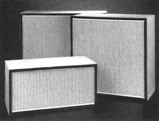
ULPA panel filters.
3.4.1.8. Clean rooms
The rapid development of microelectronic semiconductor technology and medical technology, with the increased storage density of current very large silicon integrated circuitry, requires clean rooms of class M1, in which the air needs to be over 350 times cleaner than in a basic class M3.5 and the filters should have penetrations and leaks up to 1000 times lower than normal. These requirements are met by the higher grades of HEPA and ULPA filter element. The clean room concept has spread to several industries where an increasing need is being felt for manufacture under ultra-clean atmospheres – especially in pharmaceuticals and bioprocessing.
A basic clean room system will normally be connected to a factory’s central air treatment system, with HEPA/ULPA filtration as close to the clean room as possible (Figure 3.15 ). The figure shows two different clean room arrangements connected to the air-conditioning system’s manifold, each with high-efficiency filters as near as possible to the air outlet into the room concerned. The very clean inlet air is optimally mixed with the room air so that the desired degree of purity is achieved.
Figure 3.15.
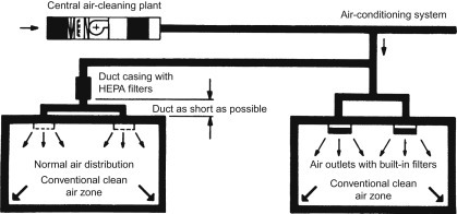
Conventional clean room filtration system.
The technical equipment is outside the clean room, enabling filter changes to be carried out also outside the clean room. The duct in the filter region may or may not be enlarged depending on the rated flow velocity and the size of high-efficiency filters used.
An alternative system is shown in the right-hand room of Figure 3.16 . This method of fitting filters gives several advantages: the air filtration takes place directly at the point of room entry; the filters also fulfil the function of distributing the air, or diffusing the stream of air. This arrangement is of particular benefit for updating existing systems.
Figure 3.16.
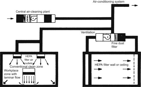
Laminar flow clean rooms.
Possible arrangements for filters in laminar flow clean rooms are shown in Figure 3.16, to create low turbulence (i.e. laminar) flow. Air is initially fed from a conventional central air-cleaning plant with second-stage filtering. A local air-conditioning plant is installed (right-hand room) for the recirculating air, which is fed to the room through a filter wall or ceiling, providing a third stage of filtration, and flows under laminar conditions through the whole room. This requires a flow velocity between 0.25 and 0.5 m/s. A large filter area is therefore necessary to provide a high volume flow, perhaps occupying the whole area of the wall or ceiling.
Where only a small part of the overall clean room requires laminar flow, the system shown in the left-hand room of Figure 3.16 may be used. Here the bulk of the room is fed from conventional air filters, with the workplace zone fed by a separate laminar flow filter.
Protection using low turbulence airflow permits germ-free air to move on parallel streamlines. The recommended velocity for vertical flow is 0.3 m/s, with 0.45 m/s recommended for horizontal flow. This is equivalent to an airflow rate of 1000–1500 m3/h/m2 of room area.
Generally, in the planning of a clean air protection scheme, it is important to limit the extension of the area protected with low turbulence displacement airflow to the absolute minimum, using the spot protection principle with restricted local use of displacement airflow, where it is feasible to do so.
3.5. Fume and Vapour Emissions
Section 3.4 has been almost entirely concerned with the filtration of air entering a workspace or living zone. Equally important are the situations where a process is generating fumes, vapours and dusts, from which people living or working in the neighbourhood must be protected. Fume and vapour emissions are covered in this section, mainly concerned with relatively low concentrations of contaminant, with dust collection in the next, Section 3.6, where contaminant concentrations can be higher.
Legislation places the onus firmly on the employer to be responsible for worker protection against fumes and vapours at the place of work. European Union Directives, for example, formalizes an approach for worker protection in industry, which is further embodied in a range of national regulations.
Industrial fumes may consist of ‘dry smoke’, such as that given off by welding operations or certain machining operations, such as laser cutting, or ‘wet smoke’ aerosols, such as oil mist or other liquid products in mist form, or mixtures of both. Such contaminants can be removed from the immediate atmosphere by extraction, which, to be properly effective, must collect the fumes at source. The heavily contaminated extract is then filtered to provide a non-polluting exhaust.
3.5.1. Collection equipment
There are at least six general methods of ventilating a working space. The first, and simplest, involves natural ventilation – leaving the room’s doors and windows open. The advantage of this method is that there is no additional investment, but it does not directly solve any problem of fume or vapour emission on the premises, and there is a high heat loss in winter.
The second also involves general ventilation of the room (Figure 3.17 ), without filtration of the exhaust. This is achieved by means of ceiling or wall-mounted fans and a high volume of air is extracted (e.g. a welding workshop must have between 3 and 15 air changes per hour in order for this method to be effective). It has a relatively low investment cost, but people on the premises are not explicitly protected from toxic fumes and, again, there is an enormous heat loss.
Figure 3.17.
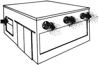
Forced ventilation.
The third method involves wall-mounted, flexible fume extractors (Figure 3.18 ), which run from the source of the fumes to an extraction manifold on the wall, so that pollutants are extracted at source and are not spread throughout the workshop. The combined exhaust passes through the exhaust fan and is discharged out from the premises, possibly through an exhaust filter. The advantage of this method is that it is more targeted and efficient than forced ventilation, with concentrated pollutants being extracted at source, before they have the opportunity to mix with the general volume of air in the room. Only a small volume of air, compared to the room size, is extracted with the fumes and optional energy-saving equipment is available. The disadvantage is that the extraction hoods must be positioned very close to the source of the fumes, which makes it difficult to mount such a system in very large production areas where walls or other fixed points may not be close to the operation in question. In addition, heat loss (or indeed conditioned air loss) will still be significant.
Figure 3.18.
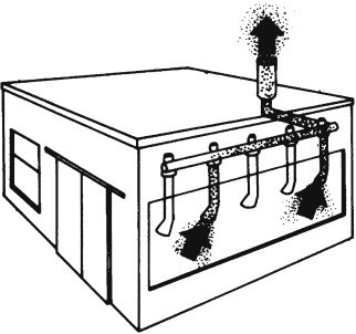
Flexible fume extraction.
The fourth method involves a mobile fume extractor with a built-in filter (i.e. an industrial vacuum cleaner). This method allows the extraction at source and the system can be moved to different locations. It is a very efficient process and saves energy as the air is cleaned and recirculated inside the workshop: no mounting is required and the machine is quick and easy to move. The filtration elements in the cleaner need to be either washed or replaced after a period of use, but this is a trivial expense or inconvenience.
The fifth method involves general central recirculation inside the room (Figure 3.19 ), through a fan-filter unit, usually mounted on the ceiling. A high volume of air is extracted from the working areas, with 100% of the air being cleaned and recirculated, thus heat loss is greatly reduced. The disadvantage is that there is no specific extraction at source, and people on the premises may still inhale toxic fumes before they are filtered. Special filters are required when toxic dusts are present and all filters must be washed or replaced regularly.
Figure 3.19.
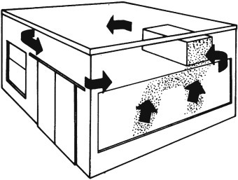
General ventilation, recirculating air within the room or hall; this has the benefit of reducing heat loss.
A final method uses wall mounted flexible fume extractors (Figure 3.20 ) with a manifold to a central extraction unit (with the previously mentioned disadvantage of connecting the flexible extractors to a convenient manifold). The system provides extraction at source and 100% recycle of the heated and filtered air. This is a very efficient method with contaminants captured before they spread throughout the workshop, and it saves energy because the heat is contained within the workshop. The hoods must be positioned by the operator, however, and this must be possible whilst remaining connected to the central extractor. Special filters are again required when noxious gases are present, and the filter elements must be washed or replaced.
Figure 3.20.
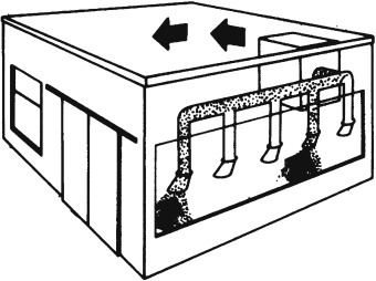
Flexible fume extraction at source and recirculation.
As with any other effluent treatment problem, the processing of fumes and vapours should be done where they are most concentrated, before they become diluted by the surrounding air. As this is rarely possible with an individual source, especially where there are several of them in the same workshop, this means that the exhausts should be extracted with as little additional air as possible – as in Figure 3.18 or Figure 3.20, rather than as in Figure 3.19.
Examples of methods for extracting unwanted fumes from the work zone are:
-
1.
Local exhaust ventilation (LEV) hoods have been the principle tool in contamination control for many years. Hoods generally require large volumes of air and may restrict light from or access to the working area. The main problem with LEVs is that the distance from the source of contamination to the hood is critical and the operator cannot be relied upon to set the system to the required distance every time, to take the fumes or vapours away. Room conditions can also affect LEV systems, particularly where unenclosed hoods are used. Cross-draughts and general room air movements can all detract from containment efficiency. Unless the material evolved is very innocuous, or the process is operator free, then LEV hoods should generally be used only as a last resort.
-
2.
Fish tails – these provide a relatively high velocity of extraction over a small area (Figure 3.21 ). Typical applications include extraction of welding fume and the removal of oil mist for certain types of unguarded machine tools. They can be mounted so that they may be moved, either on a swinging arm or by a magnetic clamp, and should in no way adversely affect the operation being undertaken (as shown in Figure 3.21). They usually have an open, slotted area approximately equal to the cross-sectional area of the extract duct (say, 300 mm×70 mm for a 150 mm square duct). Such a fish tail, extracting between 680 and 850 m3/h, may solve most problems if mounted approximately 225 mm away from the source of the fume emission. Welding fumes, because of the small area over which they are generated, may have extraction rates as low as 200 m3/h, drawn through extraction slots no more than 75 mm×25 mm. In collecting fumes directly at source, it is sometimes necessary to ensure that solid matter, such as swarf, or indeed liquid droplets are not entrained, and accordingly it will be necessary to experiment with the positioning of the fish tail to produce optimum results. The object of the exercise is to create an extraction velocity of approximately 30 m/min at the source of emission. Cross-draughts, heat and other factors will also have a bearing on the positioning and extraction rate.
-
3.
Enclosure – ideally, fumes created by operations such as machine tool working should be totally enclosed. Such enclosures help to prevent the effects of splashing and they will completely contain fumes and odours. In the case of machine tools, many machine tool manufacturers fit oil mist extraction and filtration equipment as standard. Here, again, the degree of extraction is important. The object is to design a system having an extraction rate such that relatively clean workshop air is drawn into the fume generating zone, rather than to allow the fumes to escape around the sides of the enclosure, or when the doors are opened. In order to keep the working area under the necessary negative pressure, an airflow of approximately 4.2 m3/h is required for every square metre of open area around the guards. The size of the enclosure may also have a bearing on the extraction rate, as very large enclosures will naturally require a higher rate of extraction to obtain the same air change rate. The figure quoted previously will, for most applications, provide a satisfactory solution; but, again, the point of extraction may require minor adjustment. The extraction point should, where possible, be away from the working area, so as to reduce the possibility of drawing off unwanted solid matter or liquid.
Figure 3.21.
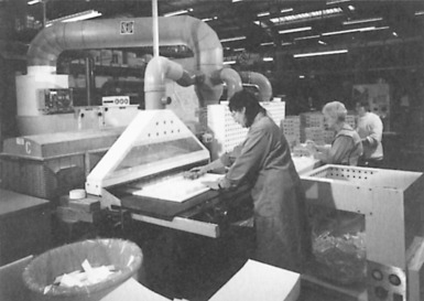
Fish tail extractor, used for packaging dust control.
Laminar flow booths contain airborne dust and vapours by inducing a flow of external air inwards through the working zone and into the filtration system. The key to their safe use is for the operator to work at the side of the source: standing downstream offers no protection from dust or vapour, and standing upstream causes a turbulent wake in front of the source, compromising operator protection. The correct inward air velocity is also imperative: too low and dust containment will fall out, but too high and turbulence in the booth may occur. Operator exposure levels will also only be as good as the background factory’s level, because the booths rely on the inward flow of a large volume of factory air and in some industries this also increases the potential of product cross-contamination. Laminar flow booths are generally best suited to operations that require enclosures no more than 1.5 m wide, handling nuisance particles with a working limit of 5–15 mg/m3.
Downflow booths have proved to be a most effective defence against airborne dust and vapours, particularly in the food industry. They operate by creating a clean laminar airflow vertically downwards from the ceiling, pushing hazardous contamination further downwards and away from the operator’s breathing zone. At low levels, the exhaust airflow is taken through a number of dust filters and HEPA filters, before the air is recirculated back to the workroom.
There are other methods of extraction, which are much less commonly employed. These include lip extractors, which may often be used around the fume-creating tanks, and powerful floor-mounted ducts, such as may be adopted in certain foundries.
In process ventilation, the air resistance in a duct-work system is mainly determined by the velocity of the air in that system, and to a lesser degree by its tortuosity. When fumes or dust is being extracted, a relatively high velocity must be maintained to prevent the dust and fume particles from settling in the ducting system. A velocity of 10–15 m/s is considered reasonable.
3.5.2. Fume filtration
Dry smoke particles may be collected using pad, bag, pocket or cartridge types of filter, with paper or synthetic media, as well as in electrostatic and electrodynamic separators. Very high efficiencies may be obtained by either method. In the case of the filters, replacement of the elements becomes necessary from time to time, whereas with the electrostatic type of unit, regular cleaning is most important. There are, however, some electrostatic units that have automatic or semi-automatic wash facilities.
Wet smokes (or aerosols) are liquid droplets ranging from 10 to 0.5 μm suspended in the air. These may be filtered by bag- or panel-type filters, electrostatic/electrodynamic separators or centrifugal impaction units. The bag or panel filter choice can be very effective and have the advantage of being cheap. However, bag changing may not be a pleasant task, and the collected matter needs disposal. Electrostatic units are more expensive, but more effective with very light contamination, as the liquid collected drains off the collection plates under gravity. A stain may build up on the plates and regular cleaning becomes necessary if the separation efficiency is to be preserved.
3.5.2.1. Centrifugal impaction separators
Centrifugal impaction units offer certain advantages and are highly effective in the removal of oil mist from machining. While they are not filtration devices, they may be used as an alternative.
In a typical unit, a perforated steel drum is directly driven by an electric motor, while blades in the drum’s interior generate suction to draw in the oil mist through suitable ducting (Figure 3.22 ). Oil mist is impacted by the blades at velocities in excess of 50 m/s, and particles are forced to coalesce before being thrown by centrifugal force against the inner surface of the outer casing. Cleaned air is returned to the workshop, while pressure within the casing ensures that the liquid oil is continually drained away through a discharge duct for reuse.
Figure 3.22.
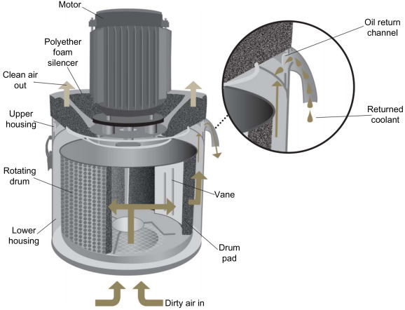
Centrifugal impaction filter.
3.5.3. Vapour treatment
Organic solvents are widely used in industry, being used in the manufacture of many essential products, but when allowed into the environment they can become health hazards. Many solvents have adverse effects on human health, while others are photochemically reactive and degrade to other hazardous species that can have a significant effect on the global climate. Collectively known as VOCs,6 their emission to atmosphere is now restricted in many countries. Accordingly, solvent removal and recovery plants treat billions of cubic metres of contaminated air every day – although much effort is also being spent on discovering ways in which solvent use can be reduced (conversion from solvent- to water-based paints for example).
The clean-up systems are based on various technologies, the oldest of which being activated carbon adsorption. This process usually comprises the passing of solvent-laden air through specially designed adsorber vessels, containing packed beds of granular or powdered activated carbon. A minimum of two adsorbers are used if continuous processing is required. Each adsorber alternates in a cycle between an adsorption step and a regeneration step. Solvents are retained in the carbon during the adsorption step, and then they are removed from the carbon, by heating, usually with steam, during the regeneration step. The resultant steam–solvent mixture is then cooled and condensed. Water insoluble solvents can then be directly reused following mechanical decantation (and probable drying), while water-soluble solvents need further separation, dehydration and possible purification, prior to reuse (Figure 3.23 ).
Figure 3.23.
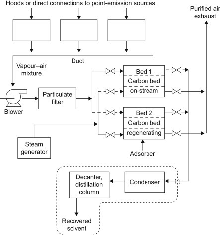
Two-bed continuously operating activated carbon adsorber system (Bed 1 is adsorbing and Bed 2 is regeneration).
An alternative carbon adsorption technology uses the cam rotary valve method, which, unlike conventional adsorption technology that employs duplex systems, uses only a single unit that is divided into multiple compartments. On a rotary basis, a central valve in the unit distributes contaminated air to an individual compartment. While each compartment in turn undergoes regeneration, using heat or steam, the rest are purifying the solvent-laden air. This device provides continuous, uninterrupted adsorption and uses less activated carbon.
Alternatively, activated carbon packs can be delivered by specialist companies in fixed vessels that can be plugged directly into exhaust gas streams. Once the activated carbon has reached a certain level of absorption, the vessel is swapped for a new one and the used media taken back for regeneration. Vessels can range from 55 gallon drums to shipping container size (Figure 3.24 ).
Figure 3.24.
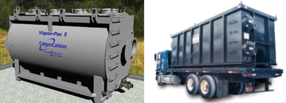
Examples of tolled absorbtive carbon vessels.
Membrane systems are also successfully employed to recover VOCs from airstreams. The membranes are used in a vapour recovery process, which combines compression–condensation and membrane vapour separation. The membrane separation step enhances the recovery possible with compression and compensation alone, allowing the process to operate at much higher recovery rates, or allowing the temperature and pressure conditions to be relaxed. This is a developing technology that shows great promise for resource recovery and pollution prevention.
3.5.3.1. Oxidizer systems
The adsorption process is intended to recover the solvent in the airstream. An alternative approach, where the economics do not favour recovery or where there are toxins present, is the destruction of the solvent contaminants. The catalytic oxidizer system shown in Figure 3.25 destroys air toxins and VOCs discharged in industrial process exhausts. The use of a catalyst allows the oxidation of hydrocarbons to carbon dioxide and water vapour at significantly lower temperatures than simple thermal oxidation. The process airstream enters the system fan, from which it passes through a heat exchanger, in which it is preheated. From the heat exchanger the air then passes through a high-temperature-resistant filter, which protects the following catalyst. In the catalyst an exothermic reaction oxidizes the VOCs and other contaminants, raising the gas temperature, so that it can be used to heat the incoming air, before being exhausted to the atmosphere.
Figure 3.25.
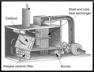
Catalytic oxidizer.
The catalytic oxidizer needs little or no added fuel provided that the solvent content of the air is high enough. Where insufficient VOC material is present to maintain combustion, extra fuel is added in a thermal oxidizer, such as the regenerative oxidizer shown in Figure 3.26 . This has two insulated, vertical thermal energy recovery chambers, connected by an inverted U-shaped insulated oxidation chamber. Flow diverter valves are located under the energy recovery chambers to divert the process airflow into and out of chambers. The energy recovery chambers are filled with ceramic material that provides for the recovery of up to 95% of the oxidation energy. The complete operation of the oxidizer system is controlled by a programmable logic controller (Figure 3.27 ).
Figure 3.26.
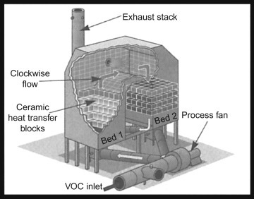
Regenerative thermal oxidizer.
Figure 3.27.
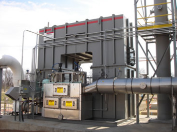
Regenerative thermal oxidizer, photograph.
3.5.3.2. Biofiltration
Biofiltration is the name given to the technique used to remove undesirable components from industrial waste gases using micro-organisms to metabolize them to less harmful substances.7 Waste gases are forced through layers of filter material, or beds of beads or similar granular material, on which micro-organisms have been immobilized. After the contaminants have been absorbed into the active surface layer, the micro-organisms break them down and transform them into products such as carbon dioxide, water and mineral salts. The filter works in a similar fashion to that of the trickle filter used for water wastes and is based on the microbiological degradation mechanism found in nature. The key is to find the suitable micro-organism, which can usually be determined using a series of tests.
In operation, waste gases are collected and fed to the filter system. Before entering the filter itself the gases may require dedusting, cooling or dehumidifying. The gas is then blown into the filter, where it is distributed evenly over the filter bed, passing through layers of the filter material that have previously been inoculated with cultured micro-organisms. The strains used vary according to the components to be removed from the gas stream; for example, nocardia cultures will be used for styrene fumes, hyphomicrobium for methylene chloride and genera thiobacillus for hydrogen sulphide. As the polluted gas stream passes through the filter, the bacteria consume the pollutants. Feed concentrations up to 5000 ppm are typical.
Applications include the treatment of solvents such as toluene and acetone, and of hydrocarbons ranging from simple alcohols to complex aromatics, as well as various sulphurous compounds. Industries where this filtration technique is proving useful include paint, printing and plastics, and the chemical and petrochemical industries. Food processing, brewing, tanning, textile manufacture and pulp and paper are other industries that may benefit, particularly for odour removal. The advantages of the biofiltration method of waste gas treatment are low operating cost, minimal maintenance and, in contrast to wet scrubbing; the filter does not produce a polluted water stream.
Some care must be taken to ensure the viability of the micro-organisms, since they are particularly sensitive to moisture level.
3.6. Dust Collectors
Most of the detailed applications examined in this handbook are concerned with contaminants that are present in their suspending fluid in only relatively low concentrations. The cleaning of gases free of dust can, however, involve quite high solid concentrations, especially where exhausts from kilns or mills or perhaps pneumatic conveying installations are concerned. At the highest concentrations, a common first step is a cyclone (Section 6), which removes suspended solids quite efficiently and delivers them in a state that is easy to handle. On the other hand, there are many applications where low concentrations must be removed completely. There is some cross-over with the equipment discussed for fume treatment, as with many filtration applications, hard categorization is not possible, as solid concentrations and airflows are a matter of degree. Much of the fume treatment equipment is equally suitable for low levels of dust collection and treatment.
The various types of dust collector that may be used are as follows:
-
•
Fabric collectors (baghouses) – relatively simple, but often very large, units available in a wide range of types and sizes with a capture range from 100 μm down to about 0.05 μm
-
•
Cyclones – working on aerodynamic principles with no moving parts and particularly suitable as primary collectors for dusts of moderate to coarse particle size (capture range down to 10 μm), or as pre-cleaners for more efficient final collectors
-
•
Multi-cyclones – groups of smaller diameter cyclones, with high collection efficiency for large exhaust gas volumes containing dust in medium concentrations (capture range down to about 8–10 μm)
-
•
Centrifugal skimmers and other similar dry working collectors operating on aerodynamic principles
-
•
Wet collectors or scrubbers – working on aerodynamic principles in conjunction with a water spray or water wash – these include cyclone- and jet-type scrubbers (capture range down to 1–2 μm) and venturi-type scrubbers (capture range down to 0.1 μm with high efficiency types)
-
•
Viscous impingement filters
-
•
ESPs – capture range down to 0.1 μm
-
•
Oil bath dust collectors – capture range down to 1 μm
-
•
Oil mist collectors – specifically designed to trap and remove oil mist
-
•
Fume extractors – hoods, fish tails and enclosures, equally capable of treating dust generation
-
•
Fume collectors – such as activated charcoal or similar adsorbent filters.
3.6.1. Filter house (baghouse)
Filter houses (widely known as baghouses, since the collecting elements are usually, but certainly not exclusively, filter bags) have a wide range of applications for dust removal from air- or gas streams, over a wide range of inlet solid concentrations, and a potential performance superior to that of most other types of separators and collectors. Fabric filters generally employ the same method of separating particulate material from the airstream. Dust-laden airflows through a fabric tube or envelope, where particles larger than the interstices in the filter medium are deposited by simple sieving action, and, in the early stages, other capture mechanisms such as interception and electrostatic deposition. A cake of dust quickly grows on the air entry surfaces of the fabric. The dust cake then acts as a highly efficient filter, capable of removing sub-micrometre dusts and fumes, while the fabric then serves principally as a supporting structure for the cake. In this sense, there is a great similarity, in terms of principle, if not execution, with candle filters for solid–liquid filtration. At a certain point, usually triggered by differential pressure, the elements are cleaned.
In terms of an efficiency rating, non-woven filter fabrics (felts and spun-bonded fleeces) are more efficient than woven fabrics, since the open areas are smaller and they possess depth. This form of fabric can be made more efficient (better at particle capture) by using smaller fibre diameters, closer packing or a greater weight of fibre per unit area of fabric. Increasing efficiency, however, typically leads to a reduction in permeability and also, often, cleanability. This is shown in Figure 3.28 , for an individual cycle.
Figure 3.28.
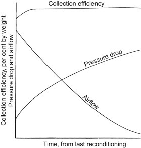
Dust collection filter performance, over one cycle.
Filtration efficiency is not a constant parameter with fabric filters. Efficiency increases, and permeability decreases, both during an individual cycle, because of the cake-filtration effect, and also during continued use over a period of weeks and months as the fabric becomes more dust-laden. The selection of fabric is thus essentially a compromise among efficiency, cleanability and permeability (Figure 3.29 ).
Figure 3.29.
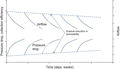
Baghouse performance over a number of cycles, showing exaggerated trends in airflow, cycle time and permebility.
No fabric dust collector can be made 100% efficient, but with proper fabric selection, adequate sizing and good design, a baghouse can operate continuously at a design efficiency well in excess of 99% for a given particle size. The end-point of a cycle of use, when the fabric must be cleaned, is when the resistance to flow causes a reduction in airflow to a value below an acceptable minimum (although, as will be shown later, a baghouse can be operated with individual element cleaning, or more typically cleaning in banks or rows of elements, so that the filter can run continuously).
One method used to improve the efficiency of a fabric dust filter medium is to apply a coating to the upstream face of the material. This can be sprayed on, or laid down as a membrane on the substrate (often a needlefelt). The membrane would consist of a large number of fine pores, which effectively carry out the filtration, restricting the particles to the surface of the membrane and thus preventing blinding due to particle penetration into the body of the substrate. The needlefelt provides the membrane with the mechanical strength to withstand the wear encountered during use. Although giving excellent results, this layered membrane may be limited in use by cost to dust filtrations that suffer from severe blinding and/or dust release problems, rather than as a generally applicable dust collection medium.
Application of a membrane to a needlefelt substrate involves the bonding of the membrane to the substrate to give a laminate. An alternative approach is to apply a microporous coating to the needlefelt substrate, to act as the septum. Unlike the membrane the coating cannot exist independently of the substrate. A fine cellular structure can now be produced by applying a polymer emulsion (by specialized coating methods) to a textile substrate. In this way, it is possible to produce a coating that remains stable throughout the coating process, resisting collapse before fully drying, and forming a regular cell structure on the substrate surface. The coating is dried without curing the polymers, thus allowing further processing to provide a microporous surface membrane. Typical applications include the filtration of PVC dust and the collection of fly ash from a coal-fired boiler on a shake clean collector.
Another factor that should be taken into account when selecting filter media is that of the stiffness of the material. Media are available in rigid, semi-rigid and flexible forms. Rigid media generally give the best filtration results, but are less able to cope with cohesive or sticky dusts, such as those with a high element of oil vapour. A semi-rigid medium can be a viable alternative if it is combined with the right cleaning mechanism.
3.6.1.1. Types of fabric filter
The basic form of a fabric filter is a large chamber (Figure 3.30 ), incorporating a clean air compartment (the top of the building in this case, above the dark line approximately 15% from the top) separated from the dirty air side by a plate or tube sheet. A number, potentially hundreds, of filter elements, either bags, with supporting inner cages or ceramic self-supporting elements are suspended from the plate, so that air passes into the filter chamber, through the filter, through the hole in the tube sheet and into the clean air chamber. Figure 3.30 clearly shows the pipes for blowback air (just above the tube sheet).
Figure 3.30.
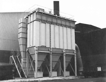
Filter baghouse.
The most common form of element in a fabric filter has a basically cylindrical tube, or bag, filter medium, with a supporting cage. The bag may actually be cylindrical (sometimes also called a stocking) or it may be flat (pocket or envelope). The performance of bags and pockets is essentially similar for the same materials and air-to-cloth ratio, the main difference being in the usual method of cleaning (Figure 3.31 ).
Figure 3.31.
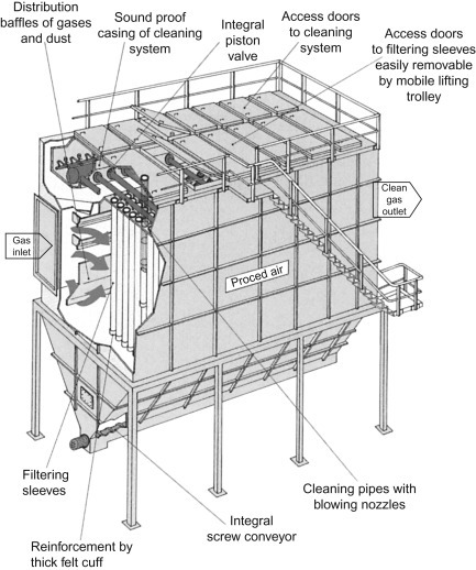
Schematic of a baghouse filter.
Pleated media cartridges or panels may also be used for fabric filters, quite often mounted horizontally in the housing (Figure 3.32 ).
Figure 3.32.
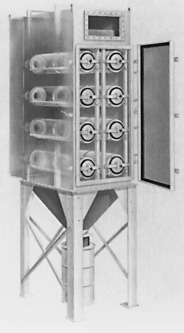
Cartridge elements in a small bag filter.
Cartridges can offer savings on space and energy. These dust filter elements are generally made of cellulose blends (paper), hydro-entangled or spun-bonded non-wovens of polyester or polypropylene (fleece), sometimes membranes. Pleat geometries vary with the different element diameters. Pleated cartridge dust filter elements can be cleaned by mechanical shaker units or more commonly by compressed air pulse-jet cleaning and reverse blow cleaning. The last of these provides a uniform cleaning effect over the entire surface of the filter element. Although residues of dust can potentially remain trapped in the pleats of such elements, in time reducing the effective area of the filter, these do not usually affect the overall performance, or lifetime, significantly.
The sizing or rating of a fabric filter is usually given directly by the air-to-cloth ratio, expressed in terms of m3/min/m2 of cloth (or other consistent units). This ratio, in effect, represents the average velocity of the gas stream through the filter medium and thus can also be termed the face velocity. Typically this may range from 0.3 to 3.5 m/min, but average figures generally range from 0.6 to 1.2 m/min. The lower the dust concentration and/or the shorter the cleaning interval, the higher the filtration velocities that may be employed. Air-to-dust ratio is also influenced by the type of dust involved and the method of cleaning employed.
3.6.1.2. Fabric filter cleaning
Common methods used for cleaning the collected dust from the elements of a fabric filter are by mechanical shaking of the whole array of elements or by low-pressure reverse air blowing or high-pressure reverse (pulse jet), either of the whole array or a section at a time, or even each element in turn. The method used depends on the fabric in use, the nature of the dust cake (e.g. has it consolidated into an integrated cake or is it simply composed of loose dust), the configuration of the elements, the design duty cycle and the housing configuration. As regards the effect of the material, felted fabrics are generally more difficult, clean and normally require pulse jet cleaning, while materials with a smooth, easy-cake-release surface can be cleaned by any method. Woven fabric elements are normally adequately cleaned by shaking or reverse flow.
Air (or gas) usually flows from outside to in for suspended bag fabric filters, so that the dust collects on the outside of each bag (which must sit on a firm wire mesh or rod cage to prevent the bag from collapsing with the pressure drop across it). A reverse-flow cleaning process causes the bag to expand away from the cage, cracking the solid cake, which then falls off the element quite easily and falls to the base of the dirty air side for removal or collection. This is shown in Figure 3.33 .
Figure 3.33.
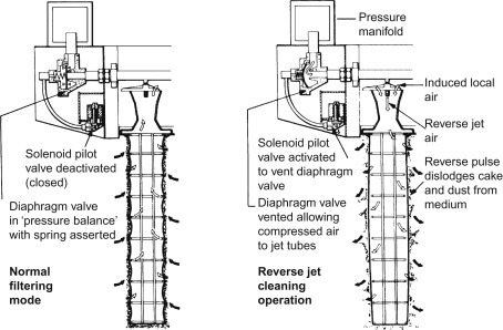
Cleaning of a single element in a baghouse filter. Typically, a large number of elements are cleaned simultaneously.
An alternative approach, to use shaker cleaning, can also be used. Figure 3.34 shows a filter in which the bags suspended from the sealed end, with the open end downwards (into which dirty airflows) with dust collecting inside the bags. The airflow causes the bags to inflate during operation and thus they do not require internal cages for support. Used mainly for intermittent duty, the bags have their airflow stopped when cleaning is required, and the tops of the bags are shaken by a vibrating mechanism to shake off the collected dust. This operation can be carried out with airflow present, i.e. with the collector in continuous service, but in this case there is a distinct possibility that disruption to the cake (which may in itself be the most significant filter medium in terms of particle capture) may cause a spike in dust carried through to the clean air outlet; cleaning will also be less effective if air continues to carry suspended dust into the bags.
Figure 3.34.
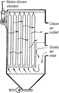
Vibration cleaning in a bag filter. In this particular case the dirty air flows into the cage and cleaned air emerges into the clean air side.
Multiple compartment collectors can be used to provide continuous collection with automatic cleaning, simply by isolating one compartment at a time for cleaning in sequence. A further advantage of this approach is that, since cleaning can be performed at short intervals, higher filtration velocities can be employed (producing a more compacted, more efficient dust cake).
The complete pulse-cleaning cycle occurs very rapidly, within a tenth of a second or less, after which normal flow is restored. Effectively, therefore, the collector operates continuously with pulse-cleaning frequency adjusted as required, typically at, say, 10 min intervals, but sometimes considerably longer. Only a small percentage of the fabric is cleaned at any one time (depending upon the number of compartments), which, together with the very short cleaning cycle, makes high filtration velocities possible. The actual filtration velocity employed may need to be limited to minimize re-entrainment of the dust from the cleaned area onto adjacent fabric surfaces. This effect is more marked with cartridge elements than with bag types.
Heightened awareness, legislation and social pressures are imposing tighter limits on the quality and quantity of gaseous emissions to the atmosphere. The limitations of fabric filters are imposed by the physical and chemical properties of the fabric media, which in general cannot withstand high temperatures and corrosive atmospheres. Ceramic filtration elements, using a mat of ceramic or mineral fibres with a fine pore distribution, have found increasing use in a number of reverse pulse-cleaning applications, for dust removal and gas treatment, particularly where hot gases and sparks are present. Typical industrial applications include non-ferrous and ferrous metal processing, coal, cement, quarries and incineration. Ceramic filter elements can be retrofitted into baghouses to increase the level of particulate removal or to reduce costs if conventional non-wovens cannot survive long enough to make an installation viable.
3.6.2. Exhaust (flue) gas treatment
The need to clean exhausts from industrial furnaces or kilns, mills, power plants or from incineration plants, and render them safe, have resulted in tightening legislation, imposing stringent discharge limits and heavy penalties for failure to comply. Gas-cleaning systems for these applications are high-performance products, ranging in type from ESPs to fabric filters (baghouses) and special filters for removal of dust and fly ash from hot gases. Cleaning systems involve semi-dry acid gas-cleaning plants, flue gas desulphurization plants (which strip SO2 from exhausts and convert it to gypsum),8 and various other types of wet process gas-cleaning plants, and enhanced all-dry scrubbing systems. Table 3.3 provides a range of exhaust gas applications.
Table 3.3.
Exhaust gas treatment applications (not including power generation or incineration)
| Steel making | Rock products | Mining |
|---|---|---|
| Electric arc furnaces | Cement kilns | Smelters |
| Open-hearth furnaces | Clinker coolers | Ore roasters |
| Basic oxygen furnaces | Perlite expanding furnaces | Calciners |
| Sintering machines | Asphalt plants | Crushing and screening |
| Kish collection | Lightweight aggregate kilns | Materials handling |
| Pelletizing plants | ||
| Foundries | Other industries | |
| Cupolas | Food processing | Pharmaceuticals |
| Sand systems | Metalworking | Woodworking |
| Abrasive cleaning | Chemical processing | Coal and coke handling |
| Reverbatory furnaces Induction furnaces | Grain handling and storage | |
Gas-cleaning systems are designed for power stations, cogeneration plants, waste incineration plants, the cement, glass and paper, metallurgical and a wide range of other industries, producing polluting flue gases. Figure 3.35 shows a schematic for part of a flue gas desulphurization plant, illustrating its complexity.
Figure 3.35.
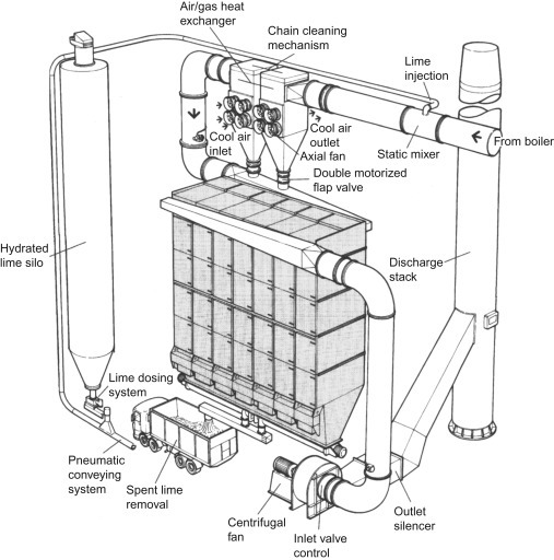
Part of a flue gas desulphurization plant.
Many different compositions of flue gases are encountered in practice. Depending on the combustion or melting process involved, the flue gases can be quite mild, or alternatively explosive and aggressive, with temperature ranging from 65°C to well over 600°C.
3.6.2.1. Dry scrubbing
The dry scrubbing process, although developed for over 30 years, has more recently become a key unit for the treatment of acid gases, particularly in the treatment of flue gases from incineration and combustion processes. Dry scrubbers may spray a powder of lime or limestone directly into the furnace, at high temperature, causing granules to become porous or cracked to further improve their absorption capability and capacity.
While removal efficiency may be relatively low (compared to wet or semi-dry scrubbing), dry scrubbing has a significantly lower cost of capital and is a simpler process. It will not suffer from the complication that liquid processes can introduce, including tendency for scale formation or the need for solid–liquid filtration (however water injection may still be needed to cool the flue gas if fabric filters are used).
While some reaction occurs as the sorbent is transported with the gas, further neutralization occurs in the dust cake on the filter bags or ceramic elements in the baghouse. Modified adsorbents (with activated carbon or coke) are also used to meet the stringent requirements regarding heavy metal and dioxin or furan removal. Generally speaking, to date, dry scrubbing installations have tended to be on a smaller scale that wet scrubbing, although larger installations are being built.
3.6.2.2. Wet scrubbing
Contaminated gases can be cleaned by passage up a tower down through which a spray of liquid is falling. The liquid may be either water or an aqueous solution chemically selected according to the nature of the contaminants, or a thin slurry of the same solids used in dry scrubbing. A similar effect can be achieved by passing the gas upwards through a packed bed of inert solids down over which there is a flow of the liquid absorbent.
For SO2 removal, an aqueous solution of lime is typically used, with oxidation of sulphur dioxide leading to the formation of calcium sulphate (as solid gypsum) which can be recovered and solid as a building material.
The gas will be cooled as it flows upwards, which may be an advantage, but it will leave the top of the absorber completely saturated with water vapour, which is probably not an advantage. The result of a wet scrubbing process is to transfer a pollution problem from a gas stream to a liquid stream, which may remain more difficult to treat.
3.6.2.3. Semi-dry processes
During the semi-dry gas-cleaning process, a liquid, usually a lime slurry, is injected into the flue gas by means of one or more spray nozzles at the top of an absorption tower. The slurry then reacts with the pollutants. Some of the liquid will evaporate into the gas stream, and it is possible with careful flow control to arrange that the effluent at the bottom of the absorber is effectively dry.
3.6.2.4. Bag filtration
Aramides (aromatic polyamides) do not burn and only lightly carburize. They are successfully used as filter media in a wide range of hot gas filtration applications. The more common applications include low shaft furnace gas scrubbing, cupola furnaces, bitumen mixing plants, waste incinerators and all types of furnaces. Polytetrafluoroethylene (PTFE) yarns and felts give outstanding temperature resistance, good chemical resistance, low differential pressure and high removal efficiency.
PTFE filter media are used where extremes of chemical and thermal conditions are encountered, such as waste burning, heavy fuel oil-fired systems, non-ferrous metal melting plant, slurry burners, carbon black producers and chlorine gas cleaners for PVC production. Mineral and glass fibre needlefelt filter media are used where temperatures range from 180°C to 300°C. They are found in dedusting of gases from electric melting furnaces and in place of precipitators in boiler firing and power stations.
Metal fibre felts are manufactured with a three-dimensional textile-like surface and can withstand heavy dust load and high airflow speeds. They are used where temperatures range from 300°C to 600°C for low pressure–high volume and high pressure–low volume reverse air cleaning. Ceramic filter elements made from ceramic fibres with inorganic reinforcement are used in extreme conditions for continuous operating temperatures up to 900°C. Filtration efficiency can be in the order of 99.99% with a maximum pressure drop of 100 mbar.
Fabric filters can cope with the majority of industrial gas-cleaning problems economically and efficiently. Filtering of hot gases before heat exchanging, catalytic oxidation in combination with bag filters, ESPs in fabric filters with conductive filter media, dry scrubbing to bind the gaseous components, anti-static performance of filter materials, adhesive dust repellent finishes and chemical protection of fibres being some of the uses.
3.6.2.5. Ceramic filters
Conventional bag filters are severely limited for very hot gas filtration, so ceramic filters and ceramic filter candles are preferred. Ceramic filter elements, typically consisting of inorganically bound ceramic fibres, are self-supporting and so do not need a supporting cage (Figure 3.36 ). The filter elements are usually temperature stable up to 900°C and, because they are almost chemically inert, they can withstand harsh chemical environments. Cleaning of the filter element is usually by similar methods to other bag or cartridge filter media, namely either by compressed air or reverse air. The pulse-jet-cleaning method is probably best since the cleaning efficiency is increased. Cold cleaning gas can be used.
Figure 3.36.
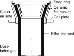
Ceramic filter element.
Ceramic filter candles have a greater tolerance to temperatures above 1000°C. They combine high burst strength and thermal shock resistance with high permeability, high filtration efficiency and corrosion resistance. They can also remove contaminants and/or recover valuable products in applications involving halogenated hydrocarbons, petrochemical processing, catalyst activations, fluid catalytic cracking, incineration of hazardous materials and combined cycle gasifiers (Figure 3.37 ).
Figure 3.37.
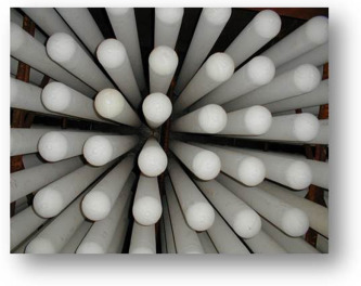
View of installed ceramic hot gas filters (looking upwards).
The structure of ceramic candles, and in particular, fibrous ceramic candles, means that they can be a suitable substrate for catalyst coating, so that they can perform selective catalytic reduction or other reactions to remove or reduce gaseous pollutants (e.g. NOx or dioxin).
3.7. Machine Air Intake Filters
Any engine or machine that uses air in a combustion chamber to burn liquid or gaseous fuel must filter the air (not to mention the fuel), in order to prevent solid particles entering and causing wear in the piston-cylinder system or of the blades of a turbine. Filtration of air drawn into a compressor or large fan is also important, to prevent similar internal damage.
The simplest form of an effective machine intake filter is an element of pleated impregnated paper, housed in a suitable casing. The pleats provide rigidity for the element, so that it requires a minimum of support, while increasing the surface area for filtration. This area may be further increased by corrugating as well as pleating the paper.
Some typical filters of this form of filter are shown in Figure 3.38 . Air is drawn from the outside to the inside of these filters, so the dust particles and other solid contaminants are trapped or stopped by the outer surface of the element, where they may remain, or fall to the bottom of the casing. Filters of this type are widely used for air cleaning on internal combustion engine air intakes and similar duties, where flow rates are moderate and pressure drop must be kept to a low figure (normally not more than 0.1–0.3 bar).
Figure 3.38.
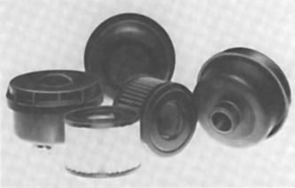
Engine air intake filters.
Variations on this simple filter include the use of pleated felts and other media, although these do not have any specific advantages over impregnated paper for light duties. Felt elements normally need support with wire mesh or similar reinforcement, to withstand pressures up to 7 bar; pleated paper is capable of withstanding pressures of that order without reinforcement. Neither type is suitable for higher pressures, even with reinforcement, without danger of disruption or at least migration of element fibres.
In the case of fabric (woven or non-woven) filters for air intake duties, detailed design of the filter element may differ appreciably from the standard pleated form. An example is shown in Figure 3.38, where the fabric is mounted on wire gauze and folded into a star-shaped formation. This results in a high surface area, without pinching at the base of the folds, and consequently low flow velocities over the surface of the fabric. A fabric element may be preferred to a paper element for heavy-duty industrial filters.
Simple dry filters may have replaceable or cleanable elements, depending on the size and design duty. Some designs provide for cleaning in place, without removal of the element, this normally being accomplished by reverse flow. A reverse-flow jet is incorporated in the centre of the filter. For reverse-flow cleaning, an air supply is connected to the top of a hollow central shaft. This shaft is then turned by hand or by a motor, to rotate the vane. A blast of air is then directed into each fold of the element in turn, blowing off the dust that has collected on the outer surface.
Where flow rates are relatively high, or the air pressure is in excess of, say, 3 bar, there is some advantage in deflecting the incoming air by louvres or vanes, or by the shape of the entry into the filter housing, so that the air enters the housing with a swirling motion. The centrifugal flow pattern that results will carry solids and moisture in suspension outwards to impinge on the housing walls. The consequent loss of particle velocity will then allow the suspended material to drop to the bottom of the housing, while the remainder of the solid passes on with the air through a filter element from the outside to the inside in the normal manner. This is the principle employed in many compressed airline filters.
Single-stage air intake filters are generally used to meet a variety of air filtration requirements for engines, compressors and blowers. They are usually mounted upright, either directly on the machinery inlet or on remote air intake piping, and can be either silenced or non-silenced. They are well able to deal with pulsating flows in dirty environments, with particle removal efficiencies of 98% of all particles 10 μm and larger being typical, at capacities up to 20,000 m3/h.
Two-stage air intake filter/silencers are usually of the panel type and are suited for centrifugal and axial compressors.
Higher performance two- and three-stage air intake filters are typically located in aggressive environments such as steel mills, iron foundries, quarries and power stations in desert locations. Filter panels having efficiencies in excess of 99.97% at 2–0.3 μm, following pre-filters, are ideal for locations where heavy contaminant loading is a problem on air intake systems.
3.7.1. Stationary installations
Stationary machines installed in factories and power stations are normally located in machine houses or separate rooms taking in air through ducting from the outside walls with suitable filters incorporated. Alternatively, the complete machine house is treated as a clean room, in which case a barrier system of conventional panel intake filters are usually installed in one wall.
For larger applications, such as gas turbines, the need for clean filtered air is essential, with some moving parts rotating at thousands of revolutions per minute. The filters may be housed in a steel box, as illustrated in Figure 3.39 , which shows a cutaway of an air intake system, complete with weather louvres. In operation, dust-laden air enters through the louvres and passes through a series of filters (pre-filter and fine filters). The cleaned air then moves into a clean air plenum and on into the turbine intake.
Figure 3.39.
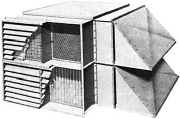
Air intake filter housing.
Filters may be cleanable or single use, sometimes also designated pulsed or static. The choice between the two will depend on environmental conditions, the quality of intake air (solids loading) and the nature of the contaminants.
A self-cleaning cycle can be performed by a timing mechanism, using compressed air blown in short bursts through blow pipes within the filter chamber directed into the filter element. This brief pressurization causes the accumulated particles to become dislodged from the filter elements. The dust is then pulled by a separate air fan into a secondary cleaning circuit, which exhausts the particles to the atmosphere away from the inlet.
Care is necessary to ensure that the type of filter used matches both the equipment and the characteristics of the application. Specifically, a more robust filter is needed where pulsating airflow has to be accommodated and static or pulsed elements are rarely interchangeable.
Increasingly, the V-block filter panels are being used for machine air intakes, especially for gas turbine systems.
Industrial air intake installations are often supplied as turnkey systems, consisting of pre-assembled modules, which are then incorporated into a basic housing. A state-of-the-art air intake filtration system would consist of eight modules:
-
•
an anti-icing unit (depending on location)
-
•
various protective screens
-
•
a pre-filter and final filter stages
-
•
a transition piece
-
•
a sound attenuator.
The schematic of Figure 3.40 shows all eight modules in a housing feeding a land-based gas turbine. Such systems are commonly used to filter the air supply to large engines and compressors, used for the generation and conditioning of energy.
Figure 3.40.
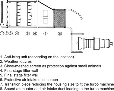
Air intake system for a gas turbine.
Ingress of moisture is a particular problem for gas turbine and other machinery intake air. Apart from the issue of the moisture itself, it can lead to particulate matter reaching sensitive machine parts in two significant ways:
-
1.
Any salts in the moisture will crystallize as the water evaporates. In this way, particles can be generated downstream of the filter. This is of particular concern for coastal area with sea mist or fog.
-
2.
Moisture can lead to corrosion (rusting) of metallic parts in the air system ducting. This rust can shed and generate dust, once again downstream of the filter and, once again, salt will worsen this effect.
For this reason, a combined coalescer filter has been developed with hydrophobic filter media and sealed channels to carry water away on the dirty side of the filter (Figure 3.41 ).
Figure 3.41.
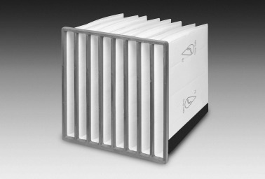
Pocket filter to remove airborne particulate matter as well as snow, mist and fog, acting as a combined filter and water coalescer. The Filtrair Drop Safe is designed for the elimination and drainage of free water and air borne salt crystals.
3.8. Vehicle Cabin Filters
One of the fastest growing segments of gas-cleaning filtration is that of the protection of drivers and passengers in those enclosed spaces that are the cabins of moving vehicles: cars, trucks, agricultural and construction vehicles, buses and coaches, trains and airplanes.
The protection needs vary somewhat for these different types of vehicle: cars and trucks take in air from road level, carrying pollen, diesel soot and general atmospheric dust; construction vehicles are often working in conditions where harmful pollutants, such as silica dust, are thrown up into the working atmosphere; multi-passenger vehicles with re-circulating air systems add the need to remove infectious bacteria and viruses from their internal air systems, and this is an especially important consideration in airplanes where people are carrying strange bacteria and other infectious micro-organisms from distant places, where the passengers remain enclosed for long periods, and where fresh air is more costly to acquire at high altitudes.
Cabin air filtration, for cars at least, was introduced with the 1939 Nash, but did not survive the demise of that marque and it was not until the mid-1980s that European manufacturers started to fit cabin air filters as standard equipment, soon followed by producers in the USA and other manufacturers quickly thereafter.
The main task in private vehicle air filtration is to keep the driver supplied with clean, conditioned air to keep him or her awake and protected against the irritation caused by inhaled pollen, and the increasing quantity of diesel soot in the atmosphere near to roads and in tunnels. The filter medium must trap particles down to sub-micron sizes, and, since the ‘clean’ air drawn in to the vehicle from the outside frequently smells anything but clean, adsorbent filtration may be required.
3.8.1. Cabin filters
An important feature of the systems used to provide vehicle cabin air filtration is that it should provide large filtration areas in a relatively small volume, since space, and of course weight, are at a premium. As a result, the media will almost certainly be pleated. It should also be relatively easily changed (a high proportion of private vehicle filters are never changed, partly because of the owner’s ignorance of where the filters are and/or how to change them) and should be readily disposable.
Given the constraints on space within vehicles, the cabin filter may be shaped specifically to fit in an odd space, so as not to take up precious room needed for the driver and passengers – the filters are thus likely to be very model-specific. The typical filter for particulate solids capture will be a three-part structure – as three separate filters if there is the space available, or, more likely, as a three-layer filter medium. The first layer is the pre-filter, intended to prevent coarse particles from reaching the fine filter, probably a non-woven fibrous material, capable of trapping pollen and mould spores, and larger soot particles.
The main filter, also a synthetic non-woven material, but now usually with electrostatically charged fibres, is capable of particle removal down to 0.05 μm. The use of electrostatically charged fibres enables the fibres to be coarser than would otherwise be the case to catch these fine particles – the finer fibres would then need a higher pressure differential across the medium.
The third layer in the cabin air filter medium is a coarser material, mainly to provide support to the fine layer.
These filter media are not expected to be cleaned when they become clogged, but to be discarded and replaced – every 12,000–15,000 miles for a private vehicle, or every 250 h of operation for a construction truck.
If odour control is also required, then this may be achieved by adding a separate activated carbon filter, or by adding a layer of this material (or of non-woven fibres in which carbon particles are embedded) to the standard three-layer particulate filtration medium.
3.9. Compressed Air Filtration
The properties of compressed air make it a versatile medium for transmission of power that is economic to produce, store and handle. Compressed air is used either as a carrier medium for the transport of energy to the point of use, where its potential and kinetic energies are converted into a driving force for pneumatic equipment, as a means to store large volumes of air (the same applies to other gases), or for processing purposes, such as agitating, mixing, packaging, conveying or pressurizing.
The increased purity demands of high-precision, complex and fully automatic pneumatic systems, and chemical, biochemical, biomedical, electronic, pharmaceutical, and food processing operations are the reasons for the continuously increasing needs for better quality compressed air.
A typical air sample is contaminated to the extent of 140 million dust particles per cubic metre (and more in heavily industrialized areas). As many as 80% of these particles are smaller than 2 μm – 25 times smaller than the smallest particle that the human eye can see – and most of them pass straight through compressor intake filters. These are supplemented by water vapour, along with unburned hydrocarbons from aviation, heating and vehicle fuels. When air of this quality is compressed to 8 bar, the particle content increases to 1.1 billion particles per cubic metre. A typical analysis of the size distribution of atmospheric dust is given in Table 3.4 .
Table 3.4.
Typical atmospheric dust analysis
| Dust size (µm) | % of total weight |
|---|---|
| <5 | 12 |
| 5–10 | 12 |
| 10–20 | 14 |
| 20–40 | 23 |
| 40–80 | 30 |
| 80–200 | 9 |
| 100 |
The contaminants likely to be found in compressed air include:
-
•
atmospheric dust, smoke and fumes inducted by the compressor
-
•
airborne bacteria and viruses
-
•
water vapour inducted by, and passed through the compressor
-
•
gases generated in the compressor
-
•
oil carried over from the compressor motor
-
•
solid contaminants generated within the system.
These contaminants can harm compressors, downstream equipment or even pressure gauges. Damage can come from scoring, given that air velocities can be very high indeed in compressed air systems, or clogging.
Table 3.5 provides the classes specified by ISO (in ISO 8573-1:2010), for contaminant concentrations. It is possible, but unusual, to mix-and-match specifications, e.g. to declare Class 2.1.1 for air with Class 2 solid particulate contamination and Class 1 for water and oil.
Table 3.5.
Compressed air contamination standards (ISO 8573-1:2010)
| Class | Solid |
Water |
Oil |
||||
|---|---|---|---|---|---|---|---|
| Maximum number of particles (per m3) |
Maximum concentration (mg/m3) | Vapour pressure dew point (°C) | Maximum amount (g/m3) | Total oil (as aerosol, liquid and vapour) (mg/m3) | |||
| 0.1–0.5 µm | 0.5–1 µm | 1–5 µm | |||||
| 0 | To be agreed between equipment user and supplier to be more stringent than Class 1, this new specification to be clearly stated in documentation |
||||||
| 1 | ≤20,000 | ≤400 | ≤10 | – | ≤−70°C | 0.001 | |
| 2 | ≤400,000 | ≤6,000 | ≤100 | – | ≤−40°C | 0.1 | |
| 3 | – | ≤90,000 | ≤1,000 | – | ≤−20°C | 1 | |
| 4 | – | – | ≤10,000 | – | ≤+3°C | 5 | |
| 5 | – | – | ≤100,000 | – | ≤+7°C | – | |
| 6 | – | – | – | ≤5 | ≤+10°C | – | |
| 7 | – | – | – | 5–10 | – | ≤0.5 | – |
| 8 | – | – | – | – | – | 0.5–5 | – |
| 9 | – | – | – | – | – | 5–10 | – |
| X | – | – | – | >10 | – | >10 | >10 |
The degree of treatment required for removing contaminants from a compressed air system depends to a great extent on the intended application. For general industrial application, for example, such as supplying a main compressed air supply line, partial water removal by aftercooling the air delivered by the compressor, followed by filtration to remove solid contaminants down to a specific size, may be adequate. At the other extreme, two or more stages of filtration may be required, including oil removal, after which the air may be further conditioned by thorough drying to provide humidity control.
Industrial stationary compressors are normally installed in separate rooms, drawing in air from the outside atmosphere, free of factory contaminants. When the level of dust concentration in the intake air is likely to be of the order of 10–50 mg/m3, it is standard practice to fit the compressor with an intake filter (usually a panel filter or a paper cartridge type, depending on the size of the compressor), having an efficiency of 99.9% based on the dust concentration present in the ambient air. The air intake filter can, therefore, be expected to pass all particles smaller than 5 μm, as well as a proportion of larger ones, in addition to atmospheric water vapour. It will also pass all gases, vapours, odours, bacteria and viruses.
The most suitable type of intake filter is normally specified by the compressor manufacturer, based on the degree of filtration desired and the operating conditions.
3.9.1. Dealing with water
Ambient air always contains some water vapour. After leaving the compressor, the air is fully saturated with vapour, any in excess of saturation having been condensed to droplets. The total amount of water present is directly proportional to the temperature of the ambient air and inversely proportional to the atmospheric pressure.
This water is best removed when the temperature of the air is at its lowest and the air pressure is at its highest, i.e. immediately upon leaving the compressor. Standard practice is to follow the compressor with an aftercoolor, which should be of sufficient size and cooling capacity to reduce the temperature of the outgoing air to within 8–10°C of the temperature of the water entering the aftercooler.
Cooling in the aftercooler may be by means of ambient air or water. When cooled by water, approximately 20 l of water will be required for every 2.5 m3 of free air being cooled in a typical system to realize the above performance. An air receiver installed following the aftercooler and located in the coolest place possible will permit further cooling and water condensation. For compressors operating in the region of 8 bar, the size of the receiver in litres should be approximately equal to 30 times the rated free air delivery of the compressor in m3/s, thus a compressor rated at 50 m3/s free air delivery requires a receiver of approximately 1500 l capacity.
As further cooling may occur in the distribution mains, these should be laid out with a fall in the direction of the airflow, so that both gravity and airflow will carry water to drainlegs located at appropriate intervals in the system. These drainlegs should be fitted with automatic drain valves to prevent their becoming flooded. Any downloops in the distribution mains should be avoided if possible, but, if this cannot be arranged, then a drainleg should be located at the bottom of the downloop. Except for the drainlegs, all take-off points for compressed air from the distribution mains should be taken from the top of the main, to prevent liquid water from entering the take-off lines.
3.9.2. Condensate
Legislation demands that oil-contaminated water be treated in compliance with the generally approved rules of engineering practice. Compressed air and gas systems produce condensate that can be aggressive, since it may be mixed with acidic compressor oil or includes noxious gases drawn into the compressor. For purification systems to operate efficiently, condensate has to be removed.
Condensate that is mainly water can be drained through drains with sensors and small orifices. Oil condensate must have drains with large orifices and other control methods.
The most important factor to avoid on small systems is the loss of compressed air by opening the drain valves unnecessarily. Pneumatically controlled condensate drains operate without the need for the cleaning of explosive gases or compressed air in an explosion risk area.
Time-controlled drains are generally used on systems where condensate levels are small and regular. Intelligent electronically controlled condensate drains combine pneumatics with electronic control and alarm. Large amounts of condensate can be handled continuously in this way without loss of compressed air.
Electronic condensate drains are favoured today because of their reliability over other types. Older designs of ball float traps have had a tendency to stick, resulting in either a failure to discharge the condensate or a permanent venting off of compressed air.
3.9.3. Condensate treatment
Oil-contaminated condensate must be treated in such a way that the oil content of the water discharged from the separator does not exceed the permissible values. At present, 20 mg/l is the most widely used maximum permissible value. However, in many cases lower limits (10 or 5 mg/l) are being imposed. Whatever the limits, compressed air condensate should be regarded as a hazardous waste. An average-sized compressor station with an air discharge rate of 20 m3/min creates annually up to 60 m3 of condensate as a waste product.
The methods for disposing of this waste involve either waste disposal or treatment. The annual average disposal cost will far outweigh the cost of a quality separation system. Oil treatment systems may consist of modular units with coalescing filters and charcoal adsorbers. Units can be connected to form a compact system. In operation, the condensate flows into a separator from the inlet, and then into an expansion chamber, where the compressed air expands to atmospheric pressure, leaving the condensate to fall to the bottom of the chamber. The compressed air expands through a demister and activated carbon bed. The condensate then flows slowly into the first of two chambers, so that no emulsion recurs and any dirt particles fall to the bottom of the chamber, which can be removed for cleaning. The condensate then flows through a coalescing filter in which the oil particles become larger and float quickly to the top to form an oil film. This film of oil is then siphoned off into a canister.
The partially cleaned water then flows through a bed of activated carbon so that it is ready to pass into the effluent system. Where stable emulsions of oil and water will not separate out it is generally considered better to use an ultrafiltration membrane unit to separate the oil and water by physical means.
Centralized compressed air purification systems, incorporating condensate oil–water separators, are becoming the standard method used to avoid polluting rivers and waterways or affecting the operation of sewage treatment plants.
3.9.4. Dehumidification
Removal of water from the compressed air to a level where no further condensation can occur in the compressed air system (i.e. the dew point is made lower than the ambient temperature) can have definite advantages in any application, and in some can be an essential feature. Examples of the advantages of drying the compressed air include:
-
•
supply to air tools, making it possible to lubricate them more efficiently
-
•
the lubrication of all pneumatic components is improved when dry compressed air is used, and servicing intervals are increased
-
•
the use of dry compressed air in spray painting equipment eliminates any risk of damage to the paint finish from water droplets in the compressed air
-
•
in blast-cleaning units, the reliability of the equipment is improved and risks of icing under outdoor conditions are eliminated
-
•
in a dry compressed air system there is no corrosion, which can lead to loss of pressure and leaks.
There is also no need for draining off of the condensed water if the air is properly dried.
For most non-critical compressed air applications, a refrigeration dryer, which will give a dew point of 3°C, will suffice. Critical applications, such as those found in the food and pharmaceutical sectors, or even in car spray painting, tend to require an adsorption dryer, capable of producing a dew point of −40°C.
Water vapour is removed in what is often called a filter dryer. A desiccant dryer must be used if a low dew point is required. This uses a bed of granular adsorbent material such as activated alumina or synthetic zeolites, through which the moist air is passed. When it is fully loaded with moisture, the bed must be regenerated by various means, usually by the use of heat or pressure swing desorption. Stainless steel screens are typically used to support and retain the granules; integral polyester spun-bonded pads prevent most particles generated by attrition from migrating downstream. Such dryers are usually fitted as duplex pairs, so that one can be regenerated while the other is drying the air.
3.9.5. Pre-filtration
Downstream from the compressor, aftercooler and receiver, the air is compressed and dried, but still carrying solid particles, some of which will have been generated in the compressor. A pre-filter is usually installed to remove most of them. The use of a pre-filter is recommended where heavy contamination by oil, water and dirt is anticipated, and is usually the first step of compressed air purification.
The pre-filter using regenerable porous filter elements, such as sintered bronze powders, sintered stainless steel powders or mesh, polyethylene or polypropylene, with pore sizes of 5–25 μm, will remove the heaviest contamination and protect the heat exchangers in the dryer. Oil- and dirt-laden compressed air flows through the filter element from the inside to outside. The coarse particles of dirt and pipe scale are retained on the inside of the pre-filter. Oil, water and the remaining fine particulate matter then pass through the pre-filter to a sub-micrometre filter. The use of such filters has become an essential part of achieving oil-free compressed air.
3.9.6. Oil removal
The problem of oil removal is complicated by the fact that oil present in compressed air can exist in three forms: liquid oil, oil–water emulsions and oil vapour. Special filters are required to remove oil vapour and oil aerosol. Modern oil removal filters are of the coalescing depth type and commonly use glass fibre elements. Oil particles of varying sizes impinge on and adhere to the fibres resulting in a gradual build-up of coalesced drops. These drops are driven to the outside of the filter by the airstream. When the oil comes to the outside of the medium, it is stopped in a porous sock covering the element. The oil then flows by the force of gravity down to the bottom of the sock, where it drops to the filter bowl. The oil is then automatically drained from the filter. These filters are capable of removing the oil content in a compressed airflow down to a level of 0.1 mg/m3 or less.
Glass microfibres are considered to be ideal filter media for the coalescing of liquid aerosols. Inherently, this material is neither adsorptive nor absorptive to liquids, and consequently is superior to natural fibre media insofar as retention of its original properties is concerned. Glass microfibres are quite hydrophobic (i.e. water repellent), so that water forms on such fibres as droplets rather than as a film, a condition that is favourable to continuing filtration efficiency. Unfortunately, neither glass nor any other material is oleophobic (oil repellent), and so oil will form as a film on glass microfibres, increasing their effective diameter. Allowance for this diameter increase, which is relatively minimal, can be made and this film of oil will not appreciably detract from filtration efficiency once the filter medium has been wetted.
Glass microfibres in the 0.5–0.75 μm diameter range usually yield the best results as a coalescing filter medium. The depth of the fibre bed and the void space to fibre space ratio are of paramount importance to the proper operation of a coalescing filter.
Filter selection is controlled by air handling capacity and filtration efficiency. Although the one dictates filter size and the other the grade of element, they are interrelated and cannot be considered independently. For standard systems, operating at about 7.5 bar, filter selection should begin by determining the maximum airflow at the point of filtration, i.e. the consumption of free air in standard litres per second before compression. Then the required air quality should be determined and then the appropriate grade of filter. This should be a balance between performance and the adverse economics of shorter element life that is inherent in more efficient filters.
Filter manufacturers provide easy-to-follow selection tables and charts to enable the determination of the correct efficiency. By referring to these charts a proper filter selection can be made, but it should always be borne in mind that the life of coalescing elements can be extended by the inclusion of a pre-filter.
Coalescing filters require an air velocity within specified limits if they are to operate efficiently. If the total volume of system air does not require filtration to the same level of cleanliness, it will be more economical overall (i.e. capital plus running costs) to install individual filters either at the point of use or in branch lines downstream of a T point. Airflows through these local filters will be lower than through a central filter system, allowing the use of smaller housings and extending the service life of the elements.
As far as maintenance of coalescing elements is concerned, the test is the pressure drop across the filter, from inlet to outlet. Most outlet filters have pressure indicators of one form or another. Typically when a pressure differential of 0.5–0.7 bar is indicated, the element must be changed.
Although the application of coalescing filtration techniques to the problem of removing sub-micrometric oil aerosols from compressed air is relatively recent, the development work upon which they are based is not. Stairmand and his colleagues in the early 1950s laid the academic groundwork for the filtration of aerosols by means of fibrous filters. Coalescing filters for the removal of oil aerosols are rapidly moving towards overcoming a longstanding obstacle in the path of the universal application of compressed air as a process and control medium. Their usage is now widespread and the only deterrent to their total acceptance is the residual reluctance of industry to try yet another device claiming the provision of completely oil-free air.
A three-dimensional layered, binder-free borosilicate microfibre web has been developed to trap 99.99999% of all oil and water aerosols and dirt particles in compressed air down to a size of 0.01 μm. These elements are chemically, biochemically and biologically neutral, and present significant advantages.
The mechanical sandwich construction of the two-stage filter element held between stainless steel support sleeves assures high filtration efficiency, even under changing pressure conditions and flow directions. Owing to the coalescing effect of the filter medium, the elements are self-regenerative as far as the removal of liquids (oil and water) is concerned. It is advisable to ensure that pre-filters fitted in the line ahead of these ultra-high-efficiency filters are capable of removing particles down to 5 μm or less, as otherwise the coalescing filter may quickly become choked with dirt. As a matter of principle, such high-efficiency oil filters should always be installed downstream of a dryer, where one is used.
Other types of coalescing filters include combination units that use three basic operations of liquid–gas surface and depth coalescing, vapour phase adsorption and final particle filtration to remove free entrained water, water–oil emulsions, free oil, oil vapours, dirt particles and some types of entrained organic liquids and vapours.
3.9.7. Sampling
The most difficult phase during the process of determining the residual oil content in compressed air is the sampling from the flowing gases. A representative sample of contaminants being transported in the gas is only possible if the sample is taken with a specially shaped probe and only with isokinetic suction. If the sample is taken incorrectly, the results can be between 100% and 1000% wrong, particularly if the air is heavily contaminated with particles and the oil droplets are greater than 1 μm in size.
3.9.8. Test filter
It is recommended that the special filter be of binder-free glass fibre web of the highest purity. The filtration effect down to 0.01 μm has to be better than an efficiency of 99.9999%. The filter element should only consist of solvent-resisting materials and should not contain any extractable components. The filter housing should have a void volume that is as small as possible and it should be totally free of clearance volume.
3.9.9. Oil vapour
Oil-free compressed air still contains hydrocarbon vapours and odours, which in the food (especially dairy), brewery and pharmaceutical industries must be removed. To effect this removal, an activated carbon filter element should be used. Such elements are normally incorporated into another filter stage, immediately downstream of the high-efficiency oil removal filters, where they should adsorb the hydrocarbon vapours and organic odours.
Filters based on activated carbon have been employed for decades to deodorize compressed air and are particularly effective for the removal of its major gaseous contaminant, oil vapour. Compressed air may also contain many species of trace gaseous contaminants, such as the oxides of carbon and nitrogen, methane, ethylene, ammonia and sulphur compounds. Activated carbon adsorption will not effectively remove these contaminants, so that, if their absence is necessary, then chemical, catalytic or selective adsorption means must be utilized to eliminate them.
Adsorption by definition is the process whereby specific molecules (the adsorbate) adhere to the surface of a porous solid (the adsorbent). It is generally agreed that the phenomenon of adsorption occurs in stages. First a single layer of adsorbate molecules attaches itself to the surface of the adsorbent; then multiple layers form and fill the finer pores in the surface; and finally the coarser pores become filled by capillary condensation. The nature of the solid surface is thus of critical importance, and it is the process of activation that gives the required high specific surface.
Activated carbon is an excellent adsorbent for oil vapour and is therefore highly suitable for the purification of compressed air. The activated carbon must be in a finely granulated state to provide the required large surface area, and the adsorber is usually in the form of a packed bed of granules, mounted in duplex form, so that one adsorber can be regenerated while the other is adsorbing.
Activated carbon has a selective preference for oil vapour (which has non-polar molecules) over water vapour (which is polar). Polar molecules are held in place by the attraction of ions of opposite electrical charge, whereas non-polar molecules are held using electron sharing. The strong affinity of carbon for oil vapour is of vital importance, since even ‘instrument quality’ compressed air contains far more water vapour than oil vapour. System conditions are also of considerable importance, since adsorption is a reversible process: temperature increase, pressure decrease and adsorbate concentration decrease all tend to promote desorption. Although system fluctuations are not usually of a magnitude sufficient for desorption to occur, they can inhibit adsorption and lower its efficiency markedly. Consequently, it is important that adsorption-type filters are located where such changes in the system conditions are minimal. The adsorption efficiency of activated carbon filters should be such that the delivered air is completely free of hydrocarbon gases and organic odours.
3.9.10. Airline filters
Standard airline filters for distribution lines generally remove particles down to about 40–50 μm in size, or lower in some cases. Finer filters can be used for better protection where required, but it is more usual to use these for second-stage filtering at the take-off point to individual supplies. In this respect, line filters fall into four categories:
-
1.
rough filters for distribution mains, capable of removing particles down to 50 μm
-
2.
medium efficiency filters, capable of removing particles in the range 5–40 μm
-
3.
fine filters, capable of removing particles in the size range 1–5 μm
-
4.
ultra-fine filters, capable of removing particles down to 0.1 μm or better.
Fine and ultra-fine filters are normally only used for second- and third-stage filtering respectively, i.e. they should be preceded by a coarser filter to remove coarser contaminants and to protect the finer filters from gross dirt contamination.
A properly designed airline filter of the correct size for the rate of flow will effectively remove liquid water but cannot reduce the water vapour content of the air. If the air is subject to further cooling after it has passed through the filter, more water may condense out of the air. If complete freedom from water contamination is wanted, the air must be properly dehumidified.
Operation of an airline filter is simple. Typically, air entering the filter passes through louvres, which direct the air into a swirling pattern. Centrifugal force throws the liquid droplets and any particulate matter outwards to the inside of the filter bowl. There they run downwards to the bottom of the bowl and drained away. A baffle prevents the turbulent air from picking up the liquid and returning it to the system. As the pressurized air leaves the bowl, it passes through a filter element that removes additional solid impurities, before the air re-enters the airline.
Airline filters can be equipped with an automatic drain to save time and labour in the draining of collected water, especially when the filter is mounted in a hard-to-reach location. All filters should be mounted vertically, and when equipped with automatic drains, a 3 mm internal diameter drain line should be used to plumb the drain away from the immediate area.
In the selection of the best filter for a specific application, a number of factors must be weighed against each other in terms of performance and cost. The initial cost of the filter may be low, but if the element needs to be replaced frequently, replacement costs may soon outweigh the initial savings. A filter with a high-efficiency rating may also have a high pressure drop, so increasing operating costs. An excessive pressure drop can also result from improper sizing or excessive flow through the chosen filter. A filter should never be selected on the basis of pipe size: compressed air filters should be sized on the basis of airflow and system pressure.
In order to prevent failures in air-operated devices, means of monitoring the filter for element replacement are necessary. Most filters rely on pressure drop through the filter as an indication of elements saturation or blockage. While some require the installation of differential pressure gauges external to the filter, others are available with differential pressure gauges or indicators mounted directly on the filter housing. Some other types require a visual check on the element, either by disassembly of the filter housing and removal of the element for inspection, or by observing a built-in colour change.
3.9.11. Element life
Probably the most frequently asked question about compressed air filters concerns the length of the working life of the elements, before they have to be replaced. With coalescing filter elements, life is determined by pressure drop, and with adsorption filters by saturation.
Generally, a longer element life can be expected if the air is compressed by a reciprocating compressor. Sliding vane and rotary screw compressors have a high oil carryover so that a shorter element life can be expected. In a rotary screw compressor, the bulk of the aerosol droplets measures between 0.1 and 0.5 μm. It is therefore advisable to fit a sub-micrometre filter if oil is to be separated from the compressed air effectively. The internal oil separator is intended to minimize oil carryover into the airstream. In the event of separator failure, large quantities of oil will be released, causing, in some cases, immediate failure of the filter element.
In terms of normal compressed air demands, filtration technology know-how has developed to the point where it is now possible to improve on the compressed air quality from an ‘oil-free’ compressor fitted with a refrigeration dryer, by using an oil-lubricated compressor in conjunction with an oil-free six-stage air treatment system.
A checklist for installing and operating compressed airline filters should include the following items:
-
1.
Determine the type of compressor lubricant used before selecting a filter. Some filter components such as gaskets, seals and transparent bowls are not compatible with certain synthetic compressor lubricants. Deterioration of these parts as a result of contact with such lubricants may cause the filters to burst and even end in personal injury.
-
2.
Ensure that the manufacturer’s pressure rating and flow capacity of the filter are equal to or exceed the pressure and flow at the point of use.
-
3.
Inspect the whole filter for shipping damage: in some cases, if one or more parts are damaged, then the entire assembly must be replaced.
-
4.
Filters should be installed downstream of aftercoolers and receivers.
-
5.
On major or critical airlines, where the air supply must not be interrupted, it is good practice to incorporate a bypass system complete with a standby filter at the filter location. This system will permit a continuous supply of air while maintenance or other work is being performed on the primary filter.
-
6.
If the filter does not incorporate an automatic drain facility, then a drain trap or drop leg should be installed below the filter, which should be drained frequently. This will prevent liquid from accumulating in the bottom of the filter housing or impairing the efficiency of the filter element. The flow capacity of the drain system should not be exceeded on startup, since compressed airlines may accumulate large amounts of water and oil while shut down.
-
7.
A compressed air filter is a pressure vessel. While in service, filters must be depressurized before any maintenance is attempted. The filter should be depressurized by slowly opening the drain or trap provided for condensate removal. Failure to depressurize slowly can result in damage to equipment and injury to personnel.
-
8.
The manufacturer’s warnings should be observed at all times with regard to cleaning the filter, to avoid danger to filter parts. Since some cleaning solvents attack seals, or transparent bowls or housings, these should be cleaned only with soap and water.
3.10. Sterile Air and Gas Filters
The demand and standards for sterile compressed air and gases are ever-increasing and selecting a sterilization filter for a compressed air or gas system can be a daunting task. The production of proteins, vaccines, antibodies, hormones, vitamins, enzymes and other biotechnology products involves highly technical processes, which require aseptic and sterile supplies of gases or liquids throughout the manufacturing cycle. The production and packaging of many food and beverage products, such as beer, yoghurt, creams and cheeses all use compressed air or carbon dioxide. Unfortunately, the nature of all these products makes them very susceptible to contamination by micro-organisms carried by the compressed air or gas.
Any product that can be contaminated by airborne bacteria must be isolated from them. In the case of foods, beverages and chemicals produced by fermentation, ingress of bacteria can cause serious defects in the products, if not their complete rejection.
In the pharmaceutical and fermentation industries, compressed air and gases are in use throughout every stage of the production process from the refining of the raw material to the manufacturing and packaging of the final product. Compressed air may be used as a source of energy in a process or as a process input. Air motors are used for explosion-free mixing of powders, for air instrumentation and in cylinders for batching materials. There are many different uses for air in the energy mode, but in every case it must be free from solid particles, carry no water or oil and have no odour taint. Figure 3.42 shows alternative schemes for the delivery of sterile air.
Figure 3.42.
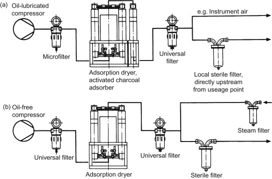
Oil-lubricated (a) and oil-free (b) arrangements for sterile compressed air delivery.
Air for process input will include aeration of liquids, seed fermentation and laboratory applications. Air for mixing into the preparatory chemicals or the ultimate product is required to be as clean and sterile as the material with which it mixes, so there can be no question of fouling by solids, liquids or micro-organisms.
Typically, the size of the bacteria can range from 0.2 to 4 μm, while viruses are less than 0.3 μm down to 0.04 μm for the smaller bacteriophages. Despite their minute size, these micro-organisms are a serious issue in many of the industries using compressed air and gases, because, as living organisms, they are able to multiply freely under the right conditions – often using the product involved in the manufacturing process.
3.10.1. Sterilizing filters
In the selection of sterilizing filters for compressed air systems (Figure 3.43 ), the following parameters should be fulfilled as the filter:
-
•
must not allow penetration of any type of micro-organism that could cause contamination
-
•
must be able to operate reliably for long periods
-
•
must use materials of construction that are inert and that do not support any bio-growth
-
•
must be economically viable, in terms of both initial cost and running costs
-
•
must be easy to install, use and maintain
-
•
must be able to be integrity tested
-
•
must be able to be steam sterilized in situ and repeatedly
-
•
must not be housed in a vessel that contains nooks, corners or dead-space that allow the accumulation of product
-
•
should be housed in a vessel whose surfaces are polished to a high level to discourage fouling or accumulation.
Figure 3.43.
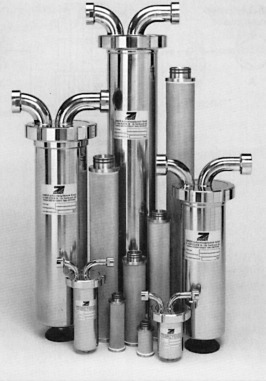
Sterile filters.
Filter media for the removal of viable organisms from compressed air tends to be either of borosilicate glass microfibres or meltspun fleece or PTFE membranes, supported on 100% glass fibre woven fabric or polysulphone or polypropylene spun-bonded textiles.
A typical binder-free borosilicate microfibre filter can offer 99.99999% efficiency at 0.01 μm and remain in service for up to 12 months. It would have a two-layer structure. The contaminated air or gas first strikes the outside layer of relatively coarse filter medium (2 μm). This filtration level allows the particles of dirt to be trapped before they penetrate into the microfibre web. This inner layer of microfibre web material traps particles down to a filtration level of 0.01 μm, which is particularly important in holding back any residual aerosol of water or oil.
These two layers of fibrous medium combine together to hold back all of the solid particles. In a dry airstream, they will also hold back bacteria, as long as the micro-organisms have no means of multiplying in the depth of the filter medium. A filter medium that contains a binder material would be considered suspect for this application, as the binder would probably act as a nutrient for bacterial growth.
Membrane cartridge filters are extremely flexible and high in tensile strength. The cartridge construction is based on a multi-layer combination of filter media in pleated format. Those polymers that have been used extensively as filtration media in coarser grades are now widely used as membrane filters. A typical format has a cartridge fabricated from a pleated filter pack, which contains a very fine polyolefin fibre pre-filter layer, two nylon membranes of the same pore (0.2 μm) size and a downstream polypropylene support. The layers of nylon microporous membrane and polypropylene pre-filter are pleated together and supported by an inner support core. The end-caps and core are melt sealed in polypropylene.
The medium is a thin (110 μm) microporous nylon membrane, having a controlled pore size. Its homogeneous cast polymer structure cannot release fibres, and no fibrous medium is used downstream of the nylon membrane (to prevent fibre migration). The only materials used in these cartridges are nylon and polypropylene, and because of this construction the cartridges can be autoclaved.
3.10.1.1. Hollow fibre cartridge
Hollow fibre filter technology was originally developed for dialysis filtration but has been adapted for a very wide range of applications, including use for the sterilization of compressed air. The main advantage of the hollow fibre format (Figure 3.43) is that the filter has a smaller spread of hole dimensions, but a large filtration area in a given housing volume. Rated retention sizes of 0.1, 0.2 and 0.45 μm are available.
Because of the much closer pore distribution than with flat membrane media, the number of pores per unit filter area is far greater, thereby extending the service life of the element. Equally a closer pore distribution means that the largest pore is considerably reduced: a conventional membrane has a maximum pore size of at least 0.3 μm larger than that of hollow fibre material. This development of membrane filter elements with a rated pore size of 0.1 μm, a longer service life and a reduced pore size distribution is a considerable aid to safer compressed air and gas sterilization, as this means the ability to retain viruses as well as bacteria.
The construction of the hollow fibre membrane also means that it is economical to manufacture in smaller capacity elements, down to a rated flow of 40 m3/h at 8 bar for laboratory use or for seed fermentation applications. The hollow fibre membrane, although it is manufactured from 100% polypropylene and is therefore hydrophobic, can be used on liquid applications provided that a wetting medium such as isopropyl alcohol (IPA) is acceptable.
3.10.2. Sterile filter systems
Sterile filter cartridges must be fitted into a pressure-holding housing, the method of sealing being by means of single- or double-sliding O-ring seals, to allow expansion and movement of the cartridge during in situ steam sterilization, and under shock load conditions, without breaking the seal. Compressed air sterilization filter housings need to be designed so as to protect the cartridge as much as possible from undue stresses or flow slugs or contamination and allow condensate to drain away freely. The housing must be manufactured to a very high standard, with the inner surface polished and it should be free of dead-spots.
Segmented filters are used quite effectively for varying flow requirements for air, gas, compressed air, liquids and steam, particularly in food and beverage applications. For compressed air and other gases, the filters use PTFE flat filter membranes that are hydrophobic and resistant to all commonly used chemicals, making them ideal for aseptic packaging operations, and food and beverage processing duties in general (Figure 3.44 ).
Figure 3.44.
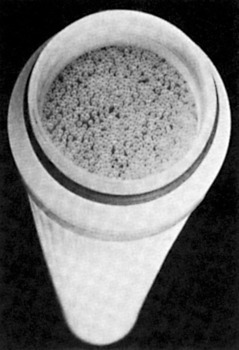
Hollow fibre filter cartridge for air sterilization.
In a typical application, air or gas flows into openings in the outside of a segment and passes through the filter medium into an adjacent segment. The filtered air or gas then leaves through openings in the centre of the cartridge and out of the filter housing.
The number of segments and type of filter media used are determined by the application. Each filter segment functions independently and the throughput can be increased by adding segments.
3.10.2.1. Oxygen filters
Oxygen is a potentially dangerous gas capable of producing violent spontaneous combustion in contact with combustible contaminants such as rust scale and other degradation products in oxygen pipelines, solvents, lubricants and greases. Equally the presence of pure oxygen can considerably lower the ignition temperature of combustible particles. The requirements for oxygen filters are thus stringent and unique, governing material choice and construction of the filter body, choice and form of the filter element, and seals and accessories.
Oxygen filter housings may be made from carbon steel or stainless steel and require high-quality construction and cleaning. Carbon steel parts are preferably fine finished and phosphated. Internal fittings may be of non-sparking bronze alloys with complete electrical loading. The design should also be such as to avoid vortex formation and minimize particle impact (to avoid particle temperature rise) with positive separation of contaminants into a calm region.
Sintered metals are a suitable choice for the filter elements, specifically sintered bronze on a stainless steel internal support. Such filters are capable of providing filtration close to 5 μm. Elements are not regarded as cleanable, but may be recoverable in the sense that the support parts may be salvaged and refitted with new bronze elements.
Oxygen enrichment using membranes is a standard process, although high-purity oxygen is not currently produced from air using membranes. Applications for oxygen-enriched air include the chemical and processing industries, steel and other metal industries, and health care. Major users of oxygen-enriched air are in gas-fired furnaces, in aerobic waste treatment processes, and in the medical sector for use by patients with respiratory problems.
The membrane modules used for air enrichment are generally of the plate-and-frame type, based on thin film silicon polymers. An oxygen filter should always be fitted with two pressure gauges, one upstream and one downstream, or alternatively with a differential pressure gauge. Such gauges must be capable of withstanding the maximum static pressure of the system on one side and atmospheric pressure on the other, without damage or losing calibration. Gauges must be thoroughly degreased for oxygen service.
3.10.2.2. Ultra-pure gases
In the chemical industry, and in the production of semiconductor components, there is a demand for the supply and storage of extremely pure gases. Hydride technology utilizes the properties of special metals and alloys, which absorb hydrogen and are highly reactive to oxidizing gases, but do not react at all to noble gases. Gas purification systems based on the reaction behaviour of the various materials have been developed to eliminate solid particles and foreign gases. The system typically consists of a number of purification stages, able to produce gases with a degree of purity of 99.99999%.
In the first stage of a typical process, ‘technical’ gases, contaminated with oxygen, hydrogen and carbon monoxide, are given a preparatory treatment by catalytic combustion, to convert as much CO and H2 as possible to carbon dioxide and water. The gases then flow through a dryer, which reduces the moisture to values below 1 ppm.
In a low-temperature purification system, the gases are then cleared of all components that, at room temperature, will react with the respective getter alloy. After this stage, the gases only contain components that do not react to metal surfaces at room temperature. The residual carbon monoxide and oxygen contents are lower than 0.1 ppm, and the water content lies below 0.5 ppm.
The gases are then taken through a high-temperature getter stage, which reduces the residual foreign gas components, excluding noble gases, to the part per billion range.
With a higher gas flow, a secondary purification of hydrogen can be carried out in alternating hydride storage systems. Since this process eliminates even the inert gas components, all foreign gas components now lie in the ppb range. If the gas is now required to be largely free from particles, it is then led through a combined deep-bed and membrane filter, to filter out particles greater than 0.02 μm.
3.10.3. Sterile filter selection
Sterile filters are normally sized according to the flow rate versus pressure drop information available. For example, a typical fermenter, requiring approximately 1 bar pressure in the compressed air feed to overcome the liquid head, may be supplied with compressed air at 16.5 bar to allow for pipe losses, valve losses and filter losses. When the filter size is being considered, firstly for pre-filtration, it is important to know whether it is operating wet or dry. The initial pressure drop across a dry filter should be around 0.07 bar; this could increase to say 0.15 bar if the filter is operating to remove liquid water and perhaps oil. The build-up in pressure drop after this is due to the dirt collecting and gradually blocking up the filter material.
Generally, coalescing-type pre-filter elements are designed to withstand very high-pressure drops; however, it is normal to replace the cartridges at somewhere between 0.3 and 0.7 bar differential pressure in an air sterilization pre-filtration application. Should more than one stage of pre-filtration be required, the total pressure loss across all the pre-filters should be kept at the same level.
The actual compressed air sterilization filter is also sized to give an initial pressure drop of around 0.1 bar, although as with the pre-filtration system, filters can be oversized to reduce this pressure drop or vice versa. However, the cost of extra differential pressure should be borne in mind.
Compressed air sterilization filters must be protected, both from normal compressed air contamination and from contamination contained in the steam used to resterilize them. It is not, therefore, normal to change them due to increased pressure drop, but when their recommended expected life has expired, as is usually stipulated by the number of repeated steam sterilizations they can safely withstand.
Routine steam sterilization is a requirement for any system of sterile filtration, and is often carried out after each batch, according to laid down procedures, although this is not absolutely necessary, provided that the filter is kept pressurized, the relative humidity is kept below recommended levels, and a small bleed of air is allowed to flow continuously. It is important to note that the sterilizing steam must be saturated and free from any additives. Dirt in the system can cause filter contamination and hence increased pressure drop, and additives also have the same effect by crystallizing on the filter medium, which may also concentrate any possible chemical effects.
In general, a well-designed system could give in the region of 12 months’ service life before cartridge replacement. The life can, of course, be shorter or much longer than this, but in any case the insignificant cost of the replacement cartridges and their easy replacement makes this of little relevance, compared to the security of the system and the likely impact of contamination.
3.10.3.1. Validation
Nothing can be left to chance when clean sterile compressed air or gases are required for fermentation, genetic engineering or pharmaceutical drug production. It is essential that any filter used has been previously integrity tested to ensure that it will perform its duty. The best way for the integrity testing of a filter element, and indeed the whole filter, is to use a cloud of test particles at the critical size of 0.1–0.3 μm. Essentially, the test is based on creating an aerosol of dioctyl phthalate (DOP) in the critical particle range, with which the filter is challenged, followed by measuring any penetration with an aerosol photometer downstream. DOP has, however, largely been replaced by other materials because of possible health hazards, and pure corn oil is now used, as are other oils giving the same type of particle size spread when atomized. Typically, some 70% of the aerosol particles generated are less than 0.3 μm, with a total particle size spread of approximately 0.05–3.0 μm.
3.11. Respiratory Air Filters
Human beings breathe in around 7 l of air per minute, for every waking minute. While the body has some mechanisms with which to protect us from some harmful contaminants, including fine hairs and mucus to trap particles, evolution has not had a chance to select for genes of those who are resistant to man-made pollutants. Even today, there are people whose lives and health are being permanently affected air quality in the workplace.
Basic non-powered air purifying respirators consist of masks (Figure 3.45 ), which can be reusable or disposable. They are designed to protect the wearer from solid particles (mildly toxic or irritant) and water-based aerosols. Disposable face masks should preferably be easy to put on, have strong head straps, soft inner face pieces and adjustable nose pieces, and they should fit well over the face. The outer shell should be resistant to moisture (Figure 3.46 ).
Figure 3.45.
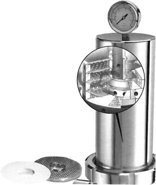
Sterile segmented filter.
Figure 3.46.
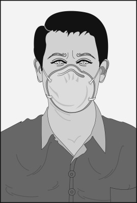
Simple respiratory mask.
Over the last few years, a number of high-profile epidemics, including severe acute respiratory syndrome (SARS) and, at the time of writing, the Ebola virus, have also increased the profile and concern for airborne diseases. In a number of countries, in particular in Asia, where air pollution is also an issue, people may wear masks on the street or in crowded spaces.9
The simplest mask is effectively made from a stiff piece of filter medium, shaped to fit approximately to the average face and has no separate filter. More sophisticated variations may comprise a rubber mask with a separate, and sometimes replaceable, filter medium panel. Respiratory face masks are used in more aggressive industrial environments: the half-mask shown in Figure 3.47 incorporates twist in/out main filters and a snap-on pre-filter. The mask flexes as the wearer breathes and speaks.
Figure 3.47.
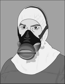
Half-mask respirator.
These masks do not protect the wearer against noxious or toxic vapours in the atmosphere. Where people are required to work in such an environment, normal practice is for the wearing of a hood, connected to an air supply, carrying air purified to respiratory air standards. The purity requirements for compressed air used for respiration and hygienically critical applications such as hospital patient recovery, and life support in hazardous environments, such as mines and underwater tanks must be free of toxic or irritating ingredients, odours, dust and other solid particles.
Most standards organizations around the world have established suitable standards pertaining to the purity of compressed air for human respiration; for example, the quality of compressed air used for breathing apparatus is specified in the European Standard EN 12021:1999. Although variations in requirements exist, primarily due to the method and type of application, most existing specifications and standards are in substantial agreement.
The most common method of producing compressed air for human respiration is by the compression of normal atmospheric air. Compressors used for this purpose may be of rotary or centrifugal, coaxial screw, piston or diaphragm type. The choice of compressor will depend on the pressure at which the air is to be used and the volume rate of air delivery required.
Generally, in low-pressure (6–7 bar) industrial systems, the breathing air supply is tapped directly from the working compressed airline. This places a premium on the correct airline installation, even though the breathing air is separately filtered. With all compressors, the main requirement is that they should be installed so that they can only induct clean and uncontaminated air as far as possible. The relative humidity of the air should be between 24% and 80% at atmospheric pressure. The acceptable temperature for breathing air is between 15°C and 25°C. The humidity requirements largely rule out the use of a dryer in the system, although a humidifier may be included in the breathing air system if a dryer is essential for other purposes: continual breathing of dry air can cause discomfort or respiratory problems. Certain types of airline lubricators can be used as humidifiers if necessary. Cooling equipment may be necessary to meet the temperature requirements.
3.11.1. Contaminants
The problems of contamination of breathing air largely echo those already described in the treatment of working supplies of compressed air, with perhaps greater emphasis on gaseous impurity removal, especially carbon monoxide.
Oil aerosol or oil vapour is present in atmospheric air as an airborne effluent from industrial processes and exhaust emissions. Lubrication in compression chambers invariably means there will be oil aerosols or vapour present in the output from the compressor.
Oil vapour content is dependent mainly on the discharge temperature and the chemical additives used by oil suppliers. Oil vapours may condense to some extent in down line pipework but will almost certainly be present as a gaseous form at the point of application, if it is not removed by prior adsorption. Ultra-high-efficiency filters are required for oil mist removal, i.e. those with an efficiency in excess of 99.9999% (at 0.01 μm).
Dirt particles are present as rust scale, pipe debris, atmospheric pollution, wear in the compressor and carbon present as unburnt hydrocarbons. Water vapour, from a physiological standpoint, is not necessarily injurious at the relative humidity figures quoted earlier, but its effect upon the equipment in the breathing air system, particularly valves and cylinders, may be quite harmful. This is where it may be best to dehumidify the air to a dew point below 0°C at atmospheric pressure, and then rehumidify at the points of breathing use.
Carbon monoxide is perhaps the most insidious danger faced by compressed air users. As a contaminant of compressed air, carbon monoxide is usually introduced through the intake port of the compressor. The compressor power drive itself, with exhaust fumes from oil-, gasoline- or gas-powered engine, without adequate venting, can be a potential source of carbon monoxide. The toxicity of carbon monoxide is due to the fact that the carbon monoxide molecule has an affinity 300 times greater for the haemoglobin molecule than does oxygen. At levels of only 2% carbon monoxide–haemoglobin involvement in the bloodstream, serious disturbances to the human psychomotor functions can occur, but this disturbance does not normally become significant until 5% involvement levels are reached. At elevated pressures, however, absorption may be more rapid and complete, and any consequent impairment to higher psychomotor functions may be disastrous.
A 2% involvement corresponds to about 10 ppm of carbon monoxide, so it should be readily appreciated that adherence to the air purity standards is absolutely essential (these call for CO contents of 5 ppm).
The difficulty in removing carbon monoxide from the air is due to its physical and chemical properties. It has a low boiling point and critical temperature, and hence is not readily adsorbed. It is almost total insoluble in most solvents and consequently cannot be easily removed by absorption. The main practical method for the effective removal of carbon monoxide at most temperatures utilizes catalytic oxidation (to carbon dioxide). Catalysis is the process in which a chemical reaction is initiated or accelerated by the presence of a catalyst, which is a material that induces a chemical reaction but which itself is unaltered during the reaction. The type of catalyst that has proved most useful for the removal or elimination of carbon monoxide, by the oxidation to carbon dioxide, is generally known as a hopcolite.
Because catalysts in general, and hopcolites in particular, are quite sensitive materials, certain precautions must be observed to ensure the required performance. It is essential that liquid and solid particulates, as well as vapours, be filtered from the airstream prior to the hopcolite, because the catalyst material is very susceptible to poisoning by the adsorption of contaminants onto its active centres. Water vapour in particular exhibits strong poisoning characteristics for hopcolites, so, to ensure a reasonable catalyst life, the compressed air must be ultra-dried by the use of desiccants.
Since the effectiveness of hopcolites is so actively limited by moisture that it requires protection by desiccants, it has become common practice to assume the catalyst to be inactive when a certain level of relative humidity of the air is exceeded. For this reason, some systems utilizing a hopcolite filter include a colour change indicator based on a moisture sensitive material. This type of indicator is, in fact, a safety device and measures air moisture content, not carbon monoxide content. Periodic testing for carbon monoxide in the cleaned air is therefore warranted where hopcolite filters are employed.
Carbon dioxide is present in the atmosphere in varying concentrations, depending upon the environment. It may be tolerated at much higher levels than carbon monoxide, but again it will impair psychomotor functions if levels are too high. Carbon dioxide is readily removed by a variety of sorbents, both absorptive and adsorptive, with the absorptive type predominating. (The economic removal of carbon dioxide from atmospheric air is a problem currently attracting a great deal of attention, as it may offer one method of countering global warming.)
Nitrous oxide and nitrogen dioxide gases are present in compressed atmospheric air as effluents from industrial processes and also from combustion in the compressor. They are irritants to the respiratory passages and can be detected in very small concentrations. Their removal is not easy. Chemical, catalytic or selective absorption means must be utilized to eliminate these impurities.
Odours are not necessarily a problem when the compressor is correctly sized, cited and maintained. However, it does not take much odour in the inlet air or created in the compressor system to produce an offensive situation in a breathing hood. The most effective and common approach to odour removal is the use of activated carbon as an adsorbent. Activated carbon filter elements have a limited effective life and need replacement at regular intervals, depending on the concentration of odorous gases that they have to adsorb, but the carbon is relatively easily regenerated.
3.11.2. Packaged systems
Several complete packaged purification systems are available that take untreated compressed air and purify it to the highest air purity standards. Purification systems are available for both high- and low-pressure use.
Systems in use include five- and six-stage treatment units, removing oil and water aerosols, carbon dioxide and acid gases, solid particles, oil vapours, odours and flavouring substances, and carbon monoxide. Typically, a good system should provide about 600 operating hours on chemical adsorption filters and up to 3000 operating hours for depth filters.
The modular system shown in Figure 3.48 has been designed specifically for use where removal of both carbon monoxide and carbon dioxide is necessary. In operation, air from a compressor passes through micro- and sub-microfilters, in which solid particles and oil and water are removed to give a residual oil content of 0.01 mg/m3. A timer-controlled solenoid valve removes the resultant condensate. The compressed air then passes through an absorber, reducing carbon dioxide content to 300 ppm. Moisture is extracted in a dryer, while oil vapours and hydrocarbons are removed in an activated carbon bed. The carbon monoxide content of the air is reduced to around 5 ppm in an oxidation stage, and finally the air passes through a dust filter to remove any abraded particles produced during the adsorption and oxidation stages.
Figure 3.48.
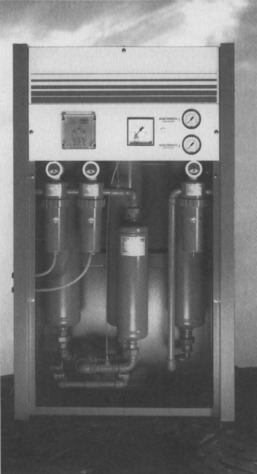
Packaged breathing air system.
Portable versions of these packaged systems are available for industrial use, as well as use by the emergency services. Whatever system is relied upon for providing high-purity air for breathing purposes, it is fundamental to the safety of the user that the specified system be capable of providing air quality of a consistently high-standard, under varying environmental, and often arduous, conditions. Product integrity, quality assurance and verification are essential characteristics of any form of breathing air equipment.
- EPA: Efficient Particulate Air filter (E10– E12)
- HEPA: High Efficiency Particulate Air filter (H13–H14)
- ULPA: Ultra Low Penetration Air filter (U15–U17)
Or, alternatively, organic hazardous air pollutants.
The term bio-scrubber is also in wide use.
The gypsum produced in this way is typically filtered from the liquid and washed using solid–liquid separation process filters such as belt filters.
The effectiveness of wearing masks in public is questionable, it may also be simply a fashion, or some people may wear them in order to prevent the spread of a cold that they have. The 2014 Beijing Marathon say a number of runners competing while wearing breathing masks.
In French: Filtres à air de ventilation générale pour l’émination des particlues – Détermination des performances de filtration.
In German: Partikel-Luftfilter für die allgemeine Raumlufttechnik – Bestimung der Filterleistung.


