Abstract
The inferomedial orbital strut (IOS) is the thin bony junction of the orbital medial wall and floor. Its fracture is common and leads to serious complications, including enophthalmos, globe dystopia and diplopia. However, anatomical restoration of the IOS is challenging owing to reduced structural support; sound anatomical background and accurate implants are therefore essential. The aim of the present study was to incorporate data from cadaveric orbit anatomy into three‐dimensional (3D) printing technology and to reconstruct the complex orbital fracture elaborately. After averaging the data from computed tomography (CT) images of 100 adult cadavers, the dimensions of the IOS were extracted, and a tangent sphere was created using a computer‐aided design program. The curves were compared with the CT data of 10 adult patients from the simulation test. Based on these data, a standardized 3D implant, 1.15 mm thick, was designed using polycaprolactone. The implant was placed in five patients with complex orbital fractures. The radius of the sphere in contact with the orbit, measuring 33.54 mm, was confirmed to be appropriate. A comparison between the normal side volume (V0) and the postoperative volume (Vpost) showed that they were statistically similar. Furthermore, a comparison between V0 and the preoperative volume (Vpre), and Vpost compared with Vpre also showed a statistically significant difference (P < 0.05). On follow‐up, the preoperative ocular symptoms were resolved. The orbital data obtained from 100 cadavers provided standardized orbital anatomy, and 3D printed implants were created. The implants were anatomically accurate with regard to the orbital cavity and adequately covered the simulation model. The implant also showed satisfactory results when applied clinically in actual patients.
Keywords: inferomedial orbital strut, orbital fracture, 3D printed implants, computer‐aided design
The aim of this study was to incorporate data from cadaveric orbit anatomy into three‐dimensional (3D) printing technology, and to elaborately reconstruct the complex orbital fracture. The orbital data obtained from 100 cadavers provided standardized orbital anatomy, and 3D printed implants were created. The implants were anatomically accurate with regard to the orbital cavity and adequately covered the simulation model and the patients.
![]()
Introduction
The inferomedial orbital strut (IOS) is the thin, triangular bony junction of the orbital medial wall and floor (Yao et al. 2016). The orbital medial wall and floor are the two most frequently fractured sites of the orbit (Hur et al. 2015), and complex fractures involving the IOS are common (Manolidis et al. 2002; Gooris et al. 2017). The IOS represents a crucial anatomical area in the orbit, and its fracture can result in serious and visible enophthalmos, globe dystopia and diplopia (Goldberg et al. 1992; Wright et al. 1999; Jordan & Anderson, 2000; Stathopoulos & Ameerally, 2018).
Reconstruction of the supportive bony structures from the orbital medial wall through the IOS to the floor is crucial (Burnstine, 2003; Jaquiery et al. 2007; Gart & Gosain, 2014; Bartoli et al. 2015); however, anatomically precise restoration of the IOS is challenging because the IOS is a conceptual structure consisting of the maxillary bone, aerated ethmoid bone and palatine bone; its thickness and hardness vary depending on the location (Kim et al. 2002). As the fracture of the IOS leads to lack of structural support, appropriate placement of the implant is compromised (Su & Harris, 2006; Hur et al., 2015). Precise anatomical knowledge of the IOS is therefore essential for restoration of the orbit.
In the present study, anatomical restoration of the fractured IOS was attempted by creating a suitable implant using three‐dimensional (3D) printing technology. The orbital implant created reproduced the curvature of the IOS using anatomical data, which were established by standardizing radiological images of 100 cadavers.
Materials and methods
Analysis of the orbital inferomedial curvature based on Korean standard data
Standard data were established based on the data obtained from the computed tomography (CT) images of 100 samples from Korean adult donors (50 men and 50 women) provided by the Korea Institute of Science and Technology Information (KISTI; Seung‐Ho et al. 2006; http://dk.kisti.re.kr).
The donated cadavers, which had no bone damage, were donated to nine university hospitals. The mean (range) ages at death were 50.3 (21–60) years for the men and 54.3 (27–60) years for the women, and the mean (range) heights were 166 (159–178) cm for the men and 156 (146–166) cm for the women. These were within the range of Korean standards.
Four‐channel CT was performed at intervals of 1 mm to obtain cross‐sectional images, and a 3D human model was established for male and female bones by KISTI. Each of the individual bone shape models adopted an averaging technique sequence to identify the centre of mass, alignment of direction, scaling, and averaging to produce an averaging model for the skeletons of men and women. An averaged individual bone shape model was reconstructed to suit the anatomical locations in order to build a sample skeleton model of the average male and female Korean.
Thereafter, 3‐matic (Materialize, Belgium), a 3D computer‐aided design program, was used to extract the dimensions of the IOS from the orbital medial wall to the floor of the skull, including the orbital surface of the maxilla, lacrimal bone, ethmoid bone, sphenoid bone, palatine bone and zygomatic bone. Using the standard data, a sphere in contact with the IOS was created, and the radius was measured (Fig. 1). After calculating the mean curvature from the measured radius, a standardized sphere was generated.
Figure 1.
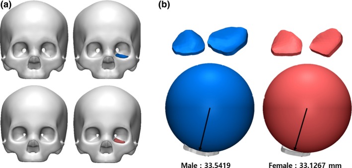
(a) Korean male and female standard skull model. (b) Measurement of the radius of the sphere to contact the orbital wall using standard skull models of males and females. [Color figure can be viewed at https://www.wileyonlinelibrary.com]
The present study was approved by our institutional review board (Catholic Medical Centre Office of Human Research Protection Program; KC18RESI0384).
Simulation of the standardized implant
To verify the reliability of the averaged curves reflecting the shape of the IOS, the generated sphere was simulated by applying it onto the patient model based on the CT data of normal adults (five men, five women) who had no trauma or disease above the neck. Using the 3D image‐processing software Mimics (Materialize), the skull, including its orbit, was visualized in three dimensions, and the standardized sphere was simulated by being placed on the IOS of the orbit. Through standardized modeling, the implant design was expanded from the curvature to the medial wall and floor. The distance between each point of the implant and the simulation model was measured to determine the accuracy of the fit and to verify the appropriateness of the implant design on the orbital wall.
Production of the Korean standardized orbital mesh implant using 3D printing technology
The standardized implant was 1.15 mm thick and was created with 3D printing technology (TnR Mesh [Orbital type]; T&R Biofab Co., Ltd, Seoul, Korea) using the biocompatible polymer, polycaprolactone (PCL), which is non‐toxic, absorbable and absorbent (Cho, 2014; Teo et al. 2015). PCL implants are radiolucent and semi‐rigid materials with structural stability.
Clinical application
The fabricated implant was applied in patients with orbital complex fractures, as confirmed on the CT or during surgery. Surgery was performed via subciliary and transcaruncular approaches under general anesthesia.
After the subciliary skin was incised, the septum was dissected from the orbicularis oculi muscle toward the infraorbital rim. Then, a transcaruncular incision was created between the orbital septum and Horner's muscle down to the periosteum. The periosteum was subsequently incised at 2 mm below the arcus marginalis, and access was gained to the fracture site in the orbital floor. Then, subperiosteal dissection was extended via the IOS to the orbital medial wall. This combined incision provided a wide opening for the surgical field and avoided detaching the inferior oblique muscle. After restoring the herniated soft tissues, the 3D‐printed implant was inserted in the subperiosteal layer, and layer‐by‐layer closure was performed.
To analyze the outcome of the surgery, the symptoms were evaluated before and after surgery, and orbital volume was measured using CT at 3 days and 2 months after surgery.
Results
Quantifying the shape of the orbital inferomedial wall
The radius of the sphere in contact with the orbital wall was derived from the standard data, and measured 33.54 mm and 33.13 mm among males and females, respectively. The average radius of the sphere in contact with the orbital floor simulated the normal adult CT data, measuring 32.93 mm and 32.49 mm among adult males and females, respectively. As a result, the male‐to‐female ratio of the standard skull model was 98.76%, and that in a normal adult was 98.66% (Table 1). Although the radius was slightly different, it was confirmed that the dimensions of the sphere calculated for the males could fit the orbits of both males and females (Fig. 2). When the standardized model, designed by expanding to the medial wall, was simulated on the CT, it covered the orbits of both male and female patients well (Fig. 3). In addition, a difference of ± 200 μm was seen when the distance between the implant and the actual orbit was analyzed (Fig. 4).
Table 1.
Comparison of the radius of sphere measured in male and female standard models and in the actual orbital wall of patients
| Sphere radius from real patients, mm | Sphere radius from real standardized model, mm | |
|---|---|---|
| Male | 32.93 ± 1.06 | 33.54 |
| Female | 32.49 ± 1.02 | 33.13 |
Figure 2.
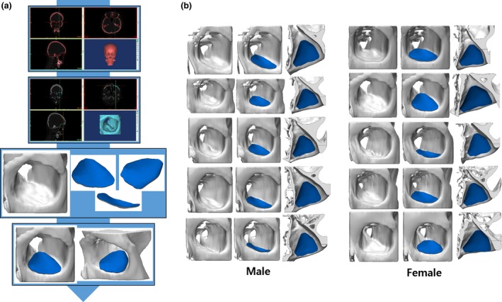
(a) Process of visualizing the two‐dimensional data from the computed tomography of the patient as a three‐dimensional (3D) model. (b) Comparison between Korean standardized orbital mesh implant and 3D simulation model. [Color figure can be viewed at https://www.wileyonlinelibrary.com]
Figure 3.
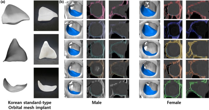
(a) Korean standard‐type orbital implant manufactured using a three‐dimensional (3D) printer. (b) Comparison between the Korean standardized orbital implant and 3D model of actual patients. [Color figure can be viewed at https://www.wileyonlinelibrary.com]
Figure 4.
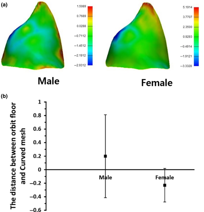
Analysis of the differences between the orbital implant and orbital wall among Koreans using triangular points of implant. (a) Colored differences between the Korean orbital mesh implant and orbital wall of actual patients. (b) Differences between Korean orbital mesh implant and orbital wall of actual patients using numerical data. [Color figure can be viewed at https://www.wileyonlinelibrary.com]
Application of the standardized implant
Based on this result, a standardized 3D implant was created and applied to five patients with orbital complex fractures. The mean (range) follow‐up period was 20.8 (18–27) months. The preoperative symptoms were diplopia accompanied by gaze discomfort and hypesthesia in one case, diplopia accompanied by hypesthesia in one case, and hypesthesia alone in two cases. The symptoms were all resolved (Table 2). The preoperative and postoperative CT were analyzed using Mimics (Materialize). Using repeated‐measures one‐way anova, we compared the normal side volume (V0) with the postoperative volume (Vpost) and found them to be statistically similar. Using the same statistical approach, we identified statistically significant differences in V0 compared to the preoperative volume (Vpre), and Vpre compared to Vpost (P < 0.05; Fig. 5).
Table 2.
Results among patients who applied standardized three‐dimensional printing implant.
| Patient number | V0, mm3 | Vpre, mm3 | Vpost, mm3 | Preoperative symptoms | Postoperative symptoms | Follow‐up period |
|---|---|---|---|---|---|---|
| 1 | 24 812 | 28 543 | 25 980 | (‐) | (‐) | 3 |
| 2 | 28 342 | 32 318 | 30 880 | Gaze discomfort, diplopia and hypesthesia | (‐) | 10 |
| 3 | 25 222 | 28 529 | 25 167 | Hypethesia | (‐) | 1 |
| 4 | 21 788 | 24 166 | 22 882 | Hypethesia | Hypethesia | 2 |
| 5 | 23 602 | 31 105 | 25 412 | Diplopia, hypesthesia | Hypethesia | 2 |
| Mean | 24 753.20 | 28 932.20 | 26 064.20 | 3.6 |
Abbreviations: V0, normal side volume; Vpre, preoperative volume; Vpost, postoperative volume.
Figure 5.
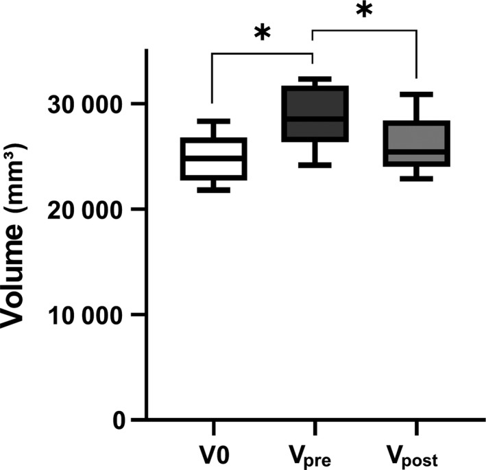
Analysis of orbital volume in preoperative and postoperative computed tomography. According to the result of repeated measured one‐way anova, normal side volume (V0) and postoperative volume (Vpost) were similar, but differences between V0 and preoperative volume (Vpre), as well as Vpre and Vpost were significant (P < 0.05).
Discussion
In the present study, orbital data obtained from 100 cadavers were used to create 3D printed implants, which were anatomically accurate and adequately covered by the simulation model. The radius of the sphere in contact with the orbit measured 33.54 mm, and was confirmed to be appropriate for the simulation model. The differences between the preoperative (Vpre), postoperative (Vpost) and normal (V0) orbital volumes were compared. V0 and Vpost were statistically similar, but the differences between V0 and Vpre, and between Vpre and Vpost were statistically significant. On follow‐up, the preoperative ocular symptoms were resolved.
Fractures of the IOS are seen frequently (Manolidis et al. 2002; Gooris et al. 2017) and can cause serious complications, including enophthalmos, orbital dystopia and double vision (Goldberg et al. 1992; Wright et al. 1999; Jordan & Anderson, 2000; Stathopoulos & Ameerally, 2018). The IOS is the important area in the orbit consisting of the thin bony junction of the orbital medial wall and floor (Yao et al., 2016), and an anatomical understanding of the IOS is essential for the reconstruction of the orbital bony structures (Burnstine, 2003; Jaquiery et al. 2007; Gart & Gosain, 2014; Bartoli et al. 2015).
The IOS is a conceptual structure consisting of adjacent orbital bones (Kim et al. 2002). It is referred to as the internal buttress of the orbits and strengthens the connection of the orbital medial wall and floor (Cornelius et al. 2014). It can be divided into three portions; the anterior IOS is formed by the maxillary bone with a small portion of the lacrimal bone, the midportion of the IOS is the junction of the maxillary bone and ethmoid bone, supported by the aerated ethmoid bone, and the posterior IOS is a triangular bone formed by the junction of the palatine and ethmoid bones, supported by the palatine bone. The total (range) length of the IOS, as measured from the orbital rim to the posterior margin of the palatine bone, was 37.6 (34–41) mm (Kim et al. 2002).
The orbital fracture is reconstructed with the aim of restoring the normal orbital volume by placing the fractured segment in an anatomically appropriate position. However, it is challenging to restore the delicate anatomy of the orbit precisely (Kim et al. 2002). It is essential to adapt the shape and position of the implant precisely to the premorbid bony contour (Stoor et al. 2014) because the accurate insertion of the implant allows restoration of optimal orbital volume and accurate form and position of the eye.
Inorganic implants, such as metal or polymer implants, have been used in the reconstruction of the orbital fracture (Ono et al. 1994; Cordewener et al. 1996; Dietz et al. 2001; Tuncer et al. 2007; Xu et al. 2009) Although the shape of the implant can be easily tailored, it is difficult to bend it accurately to achieve the exact contour as that before the injury. Inaccurate insertion of the implant can lead to complications, such as diplopia, enophthalmos, exophthalmos or restricted globe movement (Shin et al., 2013). In addition, insertion and withdrawal of the implant several times to determine the accuracy can result in an iatrogenic injury to the surrounding tissue (Kim et al. 2017).
Engineering techniques, including a rapid prototyping (RP) model, a mirrored patient‐specific implant (PSI), and 3D printing technology, have been introduced in medicine to obtain a more precise implant contour (Hassfeld & Muhling, 2001; Metzger et al. 2006; Lieger et al. 2010; Stoor et al. 2014; Kozakiewicz, 2014; Gander et al. 2015; Oh et al. 2016; Cha et al. 2017; Kim et al. 2017; Vignesh et al. 2017) RP and a mirrored PSI are highly applicable to surgery because they easily produce a complex structure similar to an orbital cavity. Aseptic treatment of the RP contour model is followed by intra‐operative molding and bending of the implant material, such as titanium, to obtain a customized implant with a precise contour that is applied at the fracture site (Vehmeijer et al. 2016; Kronig et al. 2016; Oh et al. 2016; Kim et al. 2017). A mirrored PSI is obtained by 3D reconstruction of the fractured orbit using the mirrored normal orbit as a template (Gander et al. 2015).
Although RP and mirrored PSI can be used more accurately than implants that require manual bending, they require the creation of a contour model before surgery, resulting in additional cost and preparation time. Furthermore, engineers need to be involved to produce an individualized model for each procedure. Because an orbital fracture is a common facial fracture, a ready‐made standardized implant with a precise anatomical contour is advantageous for practical application without additional cost, time and labor. The focus of the present study, therefore, was on obtaining the anatomical dimensions of the orbit, especially of the complicated structure of the IOS, because a ready‐made implant is needed to overcome the lack of structural support in the fractured IOS (Su & Harris, 2006; Hur et al. 2015).
It began with the extraction of the shape of the IOS from an average skull model. The Korean standard data were obtained from the Korean Human Model Database (http://dk.kisti.re.kr) at the KISTI (Seung‐Ho et al. 2006). The orbit medial wall through the IOS and orbital floor were extracted from the Korean standard data of the skull using 3‐matic (Materialize), and the implant was designed so that the contour would precisely fit onto the surface of the orbit. The standardization was confirmed through a simulation model, and this implant was found to have the same benefits as creating an implant with a premorbid CT scan. This design can be mass produced and standardized to meet the characteristics of Korean patients; it also reduces the manufacturing time, cost and manpower, and can be applied clinically.
The design of the implant conformed to the orbital medial wall and floor in the simulation using the CT scans of patients with orbital fractures. The 3D printing technology allows the implant to be manufactured precisely shaped, without any errors caused by manual bending. In addition, compared to the conventional pre‐bent implants using RP, mass production is possible without additional labor, cost and time.
Eventually, the status of the standardized implant is between a manual‐bending implant and PSI through RP. However, it attempted to contain the anatomical accuracy of the orbital cavity by reproduction of the orbital inferomedial wall, including the IOS, and the results were derived from simulation and actual patient surgery. Further, this is the first study to incorporate cadaveric anatomy data into 3D printing technology. Clinical data are still scarce, and the product of this study needs to be applied to more patients with complex orbital fractures. Data from clinical environments can weigh the pros and cons of using the standardized 3D‐printed implant. This might be a satisfactory bridging strategy until technological advancements make in‐house printing of the PSI possible.
Polycaprolactone is a non‐toxic, degradable, biocompatible and absorbent polymer that does not produce harmful byproducts (Cho, 2014; Teo et al. 2015). It is approved by the US Food and Drug Administration for use in various devices for medical applications, including implants, drug delivery devices, and sutures (Place et al. 2009; Stewart et al. 2018). PCL implants will disintegrate after more than 2 years (Gunatillake & Adhikari, 2003), stimulating osteogenesis. Mesh implants made of PCL have ingrowth of fibrovascular tissue before they are absorbed, leading to reduced infection, exposure and dislocation (Dougherty & Wellisz, 1994). PCL is non‐abrasive and rarely shows extrusion. It is radiolucent and shows low restitution with semi‐rigid materials and structural stability. Many studies have shown no difference in the results between absorbable and non‐absorbable implants in orbital wall reconstruction, and no significant differences are seen in long‐term follow‐up, which means that PCL is sufficient as an implant for orbital reconstruction (Hwang & Kim, 2010; Baek et al. 2014).
In conclusion, the orbital data, extracted from 100 CT scans of cadavers, provide standardized orbital anatomy and are the basis for construction of 3D printed implants. The design of the implants adequately covered the simulation model and showed satisfactory results when applied clinically in actual patients. It is anatomically accurate in the orbital cavity and can provide a sufficient bridging strategy until the in‐housing printing technology of PSI is developed.
Conflict of interest
None declared.
Acknowledgements
This work was financially supported by National Research Foundation of Korea, funded by the Ministry of Education (2017M3A9E2060428 and 2017R1C1B5017773), and by 'Supporting Project to evaluation New Domestic Medical Devices in Hospitals' funded by the Ministry of Health and Welfare and Korea Health Industry Development Institute.
Contributor Information
Jin‐Hyung Shim, Email: happyshim@kpu.ac.kr.
Suk‐Ho Moon, Email: nasuko@catholic.ac.kr.
Data availability statement
N/A.
References
- Baek WI, Kim HK, Kim WS, et al. (2014) Comparison of absorbable mesh plate versus titanium‐dynamic mesh plate in reconstruction of blow‐out fracture: an analysis of long‐term outcomes. Arch Plast Surg 41, 355–61. [DOI] [PMC free article] [PubMed] [Google Scholar]
- Bartoli D, Fadda MT, Battisti A, et al. (2015) Retrospective analysis of 301 patients with orbital floor fracture. J Craniomaxillofac Surg 43, 244–7. [DOI] [PubMed] [Google Scholar]
- Burnstine MA (2003) Clinical recommendations for repair of orbital facial fractures. Curr Opin Ophthalmol 14, 236–40. [DOI] [PubMed] [Google Scholar]
- Cha JH, Moon MH, Lee YH, et al. (2017) Correlation between the 2‐dimensional extent of orbital defects and the 3‐dimensional volume of herniated orbital content in patients with isolated orbital wall fractures. Arch Plast Surg 44, 26–33. [DOI] [PMC free article] [PubMed] [Google Scholar]
- Cordewener FW, Bos RR, Rozema FR, et al. (1996) Poly(L‐lactide) implants for repair of human orbital floor defects: clinical and magnetic resonance imaging evaluation of long‐term results. J Oral Maxillofac Surg 54(1), 9–13. [DOI] [PubMed] [Google Scholar]
- Cornelius CP, Mayer P, Ehrenfeld M, et al. (2014) The orbits–anatomical features in view of innovative surgical methods. Facial Plast Surg 30, 487–508. [DOI] [PubMed] [Google Scholar]
- Dietz A, Ziegler CM, Dacho A, et al. (2001) Effectiveness of a new perforated 0.15 mm poly‐p‐dioxanon‐foil versus titanium‐dynamic mesh in reconstruction of the orbital floor. J Maxillofac Surg 29, 82–88. [DOI] [PubMed] [Google Scholar]
- Dougherty WR, Wellisz T (1994) The natural history of alloplastic implants in orbital floor reconstruction: an animal model. J Craniofac Surg 5, 26–32. [DOI] [PubMed] [Google Scholar]
- Gander T, Essig H, Metzler P, et al. (2015) Patient specific implants (PSI) in reconstruction of orbital floor and wall fractures. J Craniomaxillofac Surg 43, 126–30. [DOI] [PubMed] [Google Scholar]
- Gart MS, Gosain AK (2014) Evidence‐based medicine: orbital floor fractures. Plast Reconstr Surg 134, 1345–55. [DOI] [PubMed] [Google Scholar]
- Goldberg RA, Shorr N, Cohen MS (1992) The medical orbital strut in the prevention of postdecompression dystopia in dysthyroid ophthalmopathy. Ophthalmic Plast Reconstr Surg 8, 32–4. [DOI] [PubMed] [Google Scholar]
- Gooris PJJ, Muller BS, Dubois L, et al. (2017) Finding the ledge: sagittal analysis of bony landmarks of the orbit. J Oral Maxillofac Surg 75, 2613–2627. [DOI] [PubMed] [Google Scholar]
- Gunatillake PA, Adhikari R (2003) Biodegradable synthetic polymers for tissue engineering. Eur Cell Mater 5, 1–16. [DOI] [PubMed] [Google Scholar]
- Hassfeld S, Muhling J (2001) Computer assisted oral and maxillofacial surgery–a review and an assessment of technology. Int J Oral Maxillofac Surg 30, 2–13. [DOI] [PubMed] [Google Scholar]
- Hur SW, Kim SE, Chung KJ, et al. (2015) Combined orbital fractures: surgical strategy of sequential repair. Arch Plast Surg 42, 424–30. [DOI] [PMC free article] [PubMed] [Google Scholar]
- Hwang K, Kim DH (2010) Comparison of the supporting strength of a poly‐L‐lactic acid sheet and porous polyethylene (Medpor) for the reconstruction of orbital floor fractures. J Craniofac Surg 21, 847–53. [DOI] [PubMed] [Google Scholar]
- Jaquiery C, Aeppli C, Cornelius P, et al. (2007) Reconstruction of orbital wall defects: critical review of 72 patients. Int J Oral Maxillofac Surg 36, 193–9. [DOI] [PubMed] [Google Scholar]
- Jordan DR, Anderson RL (2000) Orbital decompression. Ophthalmic Plast Reconstr Surg 16, 167–8. [DOI] [PubMed] [Google Scholar]
- Kim JW, Goldberg RA, Shorr N (2002) The inferomedial orbital strut: an anatomic and radiographic study. Ophthalmic Plast Reconstr Surg 18, 355–64. [DOI] [PubMed] [Google Scholar]
- Kim YC, Jeong WS, Park TK, et al. (2017) The accuracy of patient specific implant prebented with 3D‐printed rapid prototype model for orbital wall reconstruction. J Craniomaxillofac Surg 45, 928–936. [DOI] [PubMed] [Google Scholar]
- Kozakiewicz M (2014) Computer‐aided orbital wall defects treatment by individual design ultrahigh molecular weight polyethylene implants. J Craniomaxillofac Surg 42, 283–9. [DOI] [PubMed] [Google Scholar]
- Kronig SA, van der Mooren RJ, Strabbing EM, et al. (2016) Pure orbital blowout fractures reconstructed with autogenous bone grafts: functional and aesthetic outcomes. Int J Oral Maxillofac Surg 45, 507–12. [DOI] [PubMed] [Google Scholar]
- Lee S‐H, Lee JH, Cho Y‐S (2014) Analysis of degradation rate for dimensionless surface area of well‐interconnected PCL scaffold via in‐vitro accelerated degradation experiment. Tissue Eng Regen Med 11, 446–452. [Google Scholar]
- Lieger O, Richards R, Liu M, et al. (2010) Computer‐assisted design and manufacture of implants in the late reconstruction of extensive orbital fractures. Arch Facial Plast Surg 12, 186–91. [DOI] [PubMed] [Google Scholar]
- Manolidis S, Weeks BH, Kirby M, et al. (2002) Classification and surgical management of orbital fractures: experience with 111 orbital reconstructions. J Craniofac Surg 13(6), 726–737. [DOI] [PubMed] [Google Scholar]
- Metzger MC, Schon R, Weyer N, et al. (2006) Anatomical 3‐dimensional pre‐bent titanium implant for orbital floor fractures. Ophthalmology 113, 1863–8. [DOI] [PubMed] [Google Scholar]
- Oh TS, Jeong WS, Chang TJ, et al. (2016) Customized orbital wall reconstruction using three‐dimensionally printed rapid prototype model in patients with orbital wall fracture. J Craniofac Surg 27, 2020–2024. [DOI] [PubMed] [Google Scholar]
- Ono I, Gunji H, Suda K, et al. (1994) Orbital reconstruction with hydroxyapatite ceramic implants. Scand J Plast Reconstr Surg Hand Surg 28, 193–8. [DOI] [PubMed] [Google Scholar]
- Place ES, George JH, Williams CK, et al. (2009) Synthetic polymer scaffolds for tissue engineering. Chem Soc Rev 38, 1139–51. [DOI] [PubMed] [Google Scholar]
- Seung‐Ho HDSK, U‐Young L, Kwang‐Nam C, et al. (2006) Digital Korean human model database. J Korean Soc Precis Eng 21, 37–40. [Google Scholar]
- Shin JW, Lim JS, Yoo G, et al. (2013) An analysis of pure blowout fractures and associated ocular symptoms. J Craniofac Surg 24, 703–7. [DOI] [PubMed] [Google Scholar]
- Stathopoulos P, Ameerally P (2018) Reconstructing a traumatic empty orbit: principles, difficulties of treatment, and literature review. J Oral Maxillofac Surg 76(9), 1952.e1–1952.e4. [DOI] [PubMed] [Google Scholar]
- Stewart SA, Dominguez‐Robles J, Donnelly RF, et al. (2018) Implantable polymeric drug delivery devices: classification, manufacture, materials, and clinical applications. Polymers 10(12), 1379. [DOI] [PMC free article] [PubMed] [Google Scholar]
- Stoor P, Suomalainen A, Lindqvist C, et al. (2014) Rapid prototyped patient specific implants for reconstruction of orbital wall defects. J Craniomaxillofac Surg 42, 1644–9. [DOI] [PubMed] [Google Scholar]
- Su GW, Harris GJ (2006) Combined inferior and medial surgical approaches and overlapping thin implants for orbital floor and medial wall fractures. Ophthalmic Plast Reconstr Surg 22, 420–3. [DOI] [PubMed] [Google Scholar]
- Teo L, Teoh SH, Liu Y, et al. (2015) A novel bioresorbable implant for repair of orbital floor fractures. Orbit 34, 192–200. [DOI] [PubMed] [Google Scholar]
- Tuncer S, Yavuzer R, Kandal S, et al. (2007) Reconstruction of traumatic orbital floor fractures with resorbable mesh plate. J Craniofac Surg 18, 598–605. [DOI] [PubMed] [Google Scholar]
- Vehmeijer M, van Eijnatten M, Liberton N, et al. (2016) A Novel method of orbital floor reconstruction using virtual planning, 3‐dimensional printing, and autologous bone. J Oral Maxillofac Surg 74, 1608–12. [DOI] [PubMed] [Google Scholar]
- Vignesh U, Mehrotra D, Dichen,, Anand V, Howlader D. (2017) Three dimensional reconstruction of late post traumatic orbital wall defects by customized implants using CAD‐CAM, 3D stereolithographic models: a case report. J Oral Biol Craniofac Res 7, 212–218. [DOI] [PMC free article] [PubMed] [Google Scholar]
- Wright ED, Davidson J, Codere F, et al. (1999) Endoscopic orbital decompression with preservation of an inferomedial bony strut: minimization of postoperative diplopia. J Otolaryngol 28, 252–6. [PubMed] [Google Scholar]
- Xu JJ, Teng L, Jin XL, et al. (2009) Porous polyethylene implants in orbital blow‐out fractures and enophthalmos reconstruction. J Craniofac Surg 20, 918–20. [DOI] [PubMed] [Google Scholar]
- Yao WC, Sedaghat AR, Yadav P, et al. (2016) Orbital decompression in the endoscopic age: the modified inferomedial orbital strut. Otolaryngol Head Neck Surg 154, 963–9. [DOI] [PubMed] [Google Scholar]
Associated Data
This section collects any data citations, data availability statements, or supplementary materials included in this article.
Data Availability Statement
N/A.


