Abstract
Dynamic nuclear polarization (DNP) provides the opportunity to boost liquid-state magnetic resonance (MR) signals from selected nuclear spins by several orders of magnitude. A cryostat running at a temperature of around 1 K and a superconducting magnet set to between 3 and 10 T are required to efficiently hyperpolarize nuclear spins. Several DNP polarizers have been implemented for the purpose of hyperpolarized MR and recent systems have been designed to avoid the need for user input of liquid cryogens. We herein present a zero boil-off DNP polarizer that operates at 1.35±0.01 K and 7 T, and can polarize 2 samples in parallel. The samples are cooled by a static helium bath thermally connected to a 1-K closed-cycle 4He refrigerator. Using a modified version of the commercial fluid path developed for the SPINlab™ polarizer, we demonstrated that, within a 12-min interval, the system can produce two separate hyperpolarized 13C solutions. The 13C liquid-state polarization of [1-13C]pyruvate measured 26 s after dissolution was 36%, which can be extrapolated to a 55 % solid-state polarization. The system is well adapted for in vitro and in vivo preclinical hyperpolarized MR experiments and it can be modified to polarize up to 4 samples in parallel.
Keywords: hyperpolarizer, hyperpolarization, dynamic nuclear polarization, carbon-13, MRS, MRI, cryostat, cryogen free
Introduction
Dynamic nuclear polarization (DNP) has been shown to be the most efficient and versatile method for hyperpolarizing nuclear spins of molecules in solution in order to obtain enhanced magnetic resonance (MR) signals1,2. Numerous preclinical applications have demonstrated the enormous potential of hyperpolarized 13C MR for in vivo metabolic imaging and several research hospitals are currently performing studies on patients3–6. To achieve a high nuclear spin polarization by DNP, the samples containing the molecules of interest have to be doped with either a stable or a non-persistent radical and cooled to a temperature of 1-1.5 K in a magnetic field of 3-10 T7,8. Moreover, they need to be irradiated with microwaves at a frequency near the electron spin resonance (ESR) of the unpaired electron spin of the selected radical. Finally, to transform the cold samples into solutions containing molecules with hyperpolarized nuclear spins, a dissolution or a thermalization and melting process is required2,9.
The original dissolution DNP polarizer was implemented using a cryostat with a pumped liquid helium bath in which the sample is directly inserted10. In this system, the temperature of the sample is lowered by dynamically reducing the vapor pressure above the liquid surface of the helium bath using a high-flow (Roots) dry mechanical vacuum pump. Such a cryostat needs to be directly or indirectly fed with liquid helium from an external storage dewar and has an inherent large helium consumption, which despite the possibility of recycling most of the evaporated helium gas, is of increasingly growing concern due to the scarcity and cost of helium on the global market. The recent developments in cryocooler technology11 have enabled the implementation of new designs of dissolution DNP polarizers based on closed-cycle helium refrigerators, which do not require external supply of liquid helium. The most straightforward scheme incorporates a closed loop aimed at re-condensing the helium gas collected from the output of the mechanical vacuum pump to feed it back into the sample space through a circuit cooled by a cryocooler and controlled by a needle valve12. Instead of pumping directly on the sample space, it is possible to integrate a separate pumped helium bath referred to as “1-K pot”, which conductively cools the sample space. In this type of design, the sample space helium bath is usually termed “static”, as opposed to the dynamic systems referred to previously. The original implementation of this scheme in the context of DNP uses a charcoal sorption pump to cool a large (~2.5 L) 1-K pot to 0.8 K13. This system was designed to operate on a 24-h cycle and has an internal thermal switch enabling the helium gas trapped inside the sorption pump to be recondensed back into the 1-K pot during the night. No other practical pumping technique can reach temperatures as low as 0.8 K in a 4He bath14. A simplification of this design employs a dry mechanical pump instead of the bulky sorption pump, the output of which is connected to a tank from which the helium is recondensed and sent back into a 0.5 L 1-K pot15,16. This design necessitates a careful adjustment of the liquid helium input into the 1-K pot via a manually-operated needle valve.
This manuscript presents the design and performances of an alternative model of zero boil-off DNP polarizer. Rather than lowering the vapor pressure above the liquid helium surface of a large-volume 1-K pot, a small 1-K pot (containing 0.05 L of liquid helium) is cooled within a closed loop by expanding the circulating helium through a flow restriction, as previously described by Uhlig17. The 1-K pot is bolted onto a gold-platted oxygen-free copper plate, herein after referred to as the 1-K plate, which supports a conductively-cooled (“dry”) 7 T superconducting magnet. The 1-K plate is thermally connected to a static helium bath inside the sample space. This polarizer is designed to accommodate for up to 4 samples that can be polarized simultaneously and dissolved independently.
Experimental
Cryostat and magnet
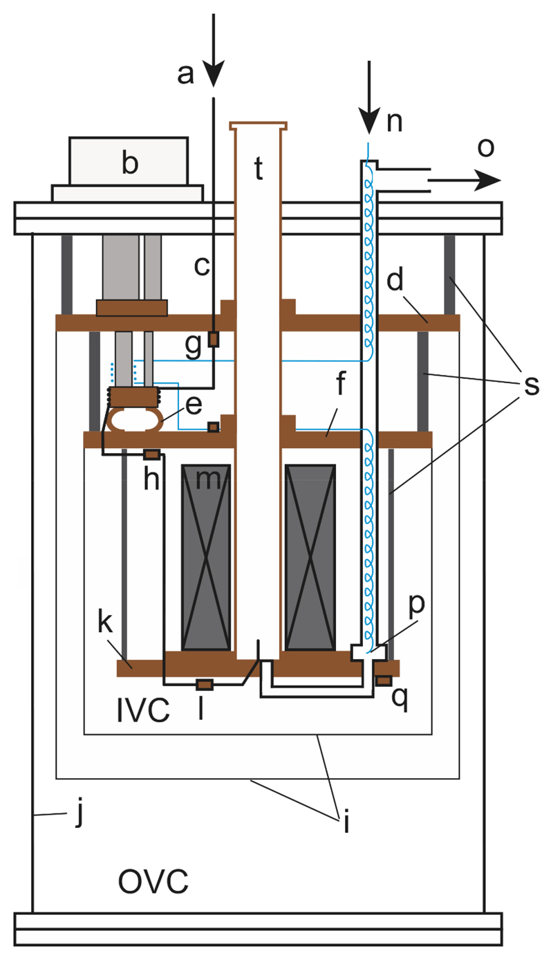
The polarizer is implemented around a modified commercial dilution refrigerator (CF-CS50 series, Leiden Cryogenics BV, Leiden, The Netherlands) inside which the lowest cooling stage consisting of a 3He/4He circuit has been removed (Fig.1). The cryostat consists of three gold-platted oxygen-free copper plates hanging from a room-temperature stainless steel top flange. These plates are named after their nominal running temperature, the actual temperature of each plate depending on the operating conditions: the 50-K and 3-K plates are respectively thermally anchored to the first and second stage of a high-power pulse-tube cryocooler (PT415 RM, Cryomech, Syracuse, USA), and the 1-K plate, which defines the base temperature of the cryostat, is cooled by a closed-cycle recirculating 4He refrigerator that has its own isolated helium supply. The recirculation is driven by a dry mechanical vacuum pump (GX100L, Edwards, UK) and the flow restriction that feeds the cooled liquid helium into the 1-K pot as well as the sequence of heat exchangers are similar to the ones described for the 4He 1-K loop in ref. 17.
Figure 1.
Schematic drawing of the cryostat without insert: (a) helium gas inlet, (b) cryocooler, (c) helium filling capillary, (d) 50-K plate, (e) copper flexible strap, (f) 3-K plate, (g) thermometer on 50-K plate, (h) thermometer on 3-K plate, (i) radiation shields, (j) vacuum can, (k) 1-K plate, (l) RuO2 thermometer on helium inlet, (m) magnet, (n) input port of 1-K recirculation circuit to high-impedance capillary, (o) output port of 1-K recirculation circuit to dry vacuum pump, (p) 1-K pot, (q) RuO2 thermometer on 1-K plate, (s) supporting rods, (t) sample tube.
The sample space of the cryostat is cooled by the 1-K plate through thermal conduction. The inner diameter of the tube connecting the top plate to the sample space is 49 mm (see Fig.1) and this tube is thermally anchored to the various cold plates. Liquid helium is condensed into the sample space from an external room-temperature gas cylinder.
A conduction-cooled 7 T superconducting magnet (Cryogenic Ltd, London, UK) is thermally anchored to the 1-K plate. The magnet has a specified homogeneity of 50 ppm over a 20-mm diameter and 20-mm long cylinder that allows the simultaneous polarization of multiple samples. The magnet can be ramped to 7 T (118.65 A) in less than 40 min and the field is maintained in non-persistent mode, through connection to the power supply during operation.
The monitoring instrumentation includes two capacitive manometers (one connected to the 1-K pot and one connected to the sample space; Pfeiffer Vacuum Schweiz AG, model CMR 362), a flow meter for the recirculating flow (Aalborg, Orangeburg, USA) and three 10-kΩ ruthenium oxide (RuO2) thermometers, calibrated at zero magnetic field in the region 1 to 4 K (Leiden Cryogenics BV, Leiden, The Netherlands). These thermometers are mounted on the outside bottom of the 1-K pot, on the outside bottom of the sample space, and on the DNP insert. The DNP insert can be equipped with a capacitive liquid He level sensor.
To determine the cooling power of the system, a test insert was built with both a 100-Ω heater and a 10-kΩ RuO2 thermometer. Such thermometers have a non-negligible magnetoresistance and a calibration table (not shown) was established to provide the accurate sample bath temperature at 7 T. All DNP data reported in this paper were obtained with the field set to 7 T.
Starting with the cryostat initially at room temperature and with the test or DNP insert inside the pumped sample space (~10-1 mbar), it takes 36 h to cool and stabilize the 3-K plate to 2.9±0.2 K once the cryocooler has been turned on. The recirculation of the 1-K refrigerator is then initiated and the 1-K plate reaches its base temperature within 45 min. At that point, a volume of ~85 mL of liquid helium is condensed into the sample space at a controlled rate of 1.5 to 3 L of helium gas per minute at standard temperature and pressure (STP), which takes about 1 h. From the geometry of the sample space and the microwave cavity of the DNP insert, it can be deduced that 1/3 of the total volume of the cavity is filed with liquid helium. It takes less than 40 h to complete the cool-down and filling process followed by ramping the magnet to 7 T. The final state can be maintained without any manual operation to run continuously in a 24/7 operation mode. There is no need to refill the sample space even after dissolution DNP experiments have been performed.
DNP insert
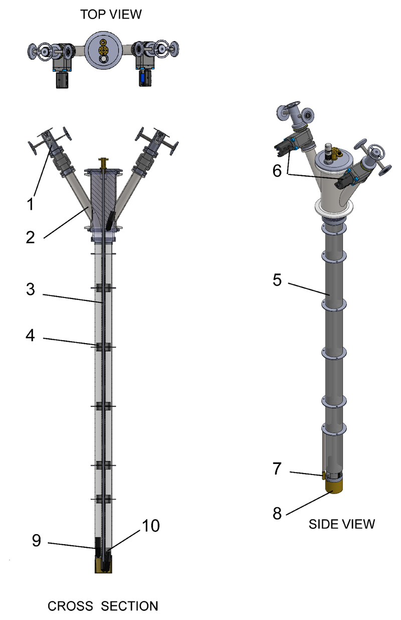
The cryogenic/bottom part of the multi-sample DNP insert was designed to accommodate 4 sample vials of up to 2 mL each. However, the room-temperature/top section of the specific implementation presented in this manuscript was restricted to just 2 sample access tubes (see Fig.2). The top flange of the access tubes was designed to fit the vial and the dynamic seal assembly of the fluid path developed by General Electric for the SPINlab™ polarizer13. Each access tube is equipped with a pressurize and purge assembly and a KF 16 gate valve (mini gate valve VATLOCK, VAT, Switzerland). Similarly to a previously published design18, the waveguide to transmit the microwave from the insert top flange to the sample is a thin-wall straight stainless steel tube (4 mm outer diameter and 0.18 mm wall thickness) symmetrically placed along the main axis of the sample tube. 3D-printed polylactic acid (PLA) fitting parts were stacked along the waveguide and used to restrict each sample vial within one of the four quadrants of the section of a fiberglass tube (32 mm inner diameter) suspended from a 3D printed sample guide block attached to the insert top flange (KF50). Five of the fitting parts inside the fiberglass tube are covered with multilayer insulation and act as internal baffles to limit radiation heating from the top plate and convection inside the fiberglass tube. Another set of concentric baffles, made from copper-coated printed circuit board (PCB), positioned at the same level as the internal baffles and in line with the cryostat’s cooling plates, were glued (Dymax 1121-M UV curing glue) to the outside of the fiberglass tube to reduce radiation heating and act as a thermal anchor. A tapered circular microwave flange soldered to the top end of the waveguide holds the assembly in place from the insert top flange. A split 197-GHz microwave source (ELVA-1, St. Petersburg, Russia) is directly connected to the microwave flange. A polyether ether ketone (PEEK) positioner is secured to the lower end of the waveguide to ensure that the vials slide into a brass microwave cavity (see 10 in Fig.2). The microwave cavity, in turn, is secured to the PEEK positioner and acts to improve the microwave power density by confining the microwaves within a volume of 24 mL. A radiofrequency (RF) coil printed on a 0.1 mm thick flexible polymer sheet is placed around the PEEK positioner. Fixed tuning and matching capacitors were soldered next to the coil and connected to a semi-rigid coaxial cable (RG405, Times Microwave Systems, USA) to form a 13C MR probe resonating at 75.15 MHz. To fine tune the probe, an external room-temperature tuning and matching RF circuit was added between the output of the semi-rigid coaxial cable and the home-made solid-state MR spectrometer19.
Figure 2.
DNP insert designed and used for dissolution DNP; (1) airlock, (2) sample access tube, (3) waveguide, (4) internal baffle, (5) fiberglass tube, (6) gate valve, (7) calibrated RuO2 thermometer, (8) microwave cavity, (9) sample vial and (10) RF coil.
Custom-designed fluid paths
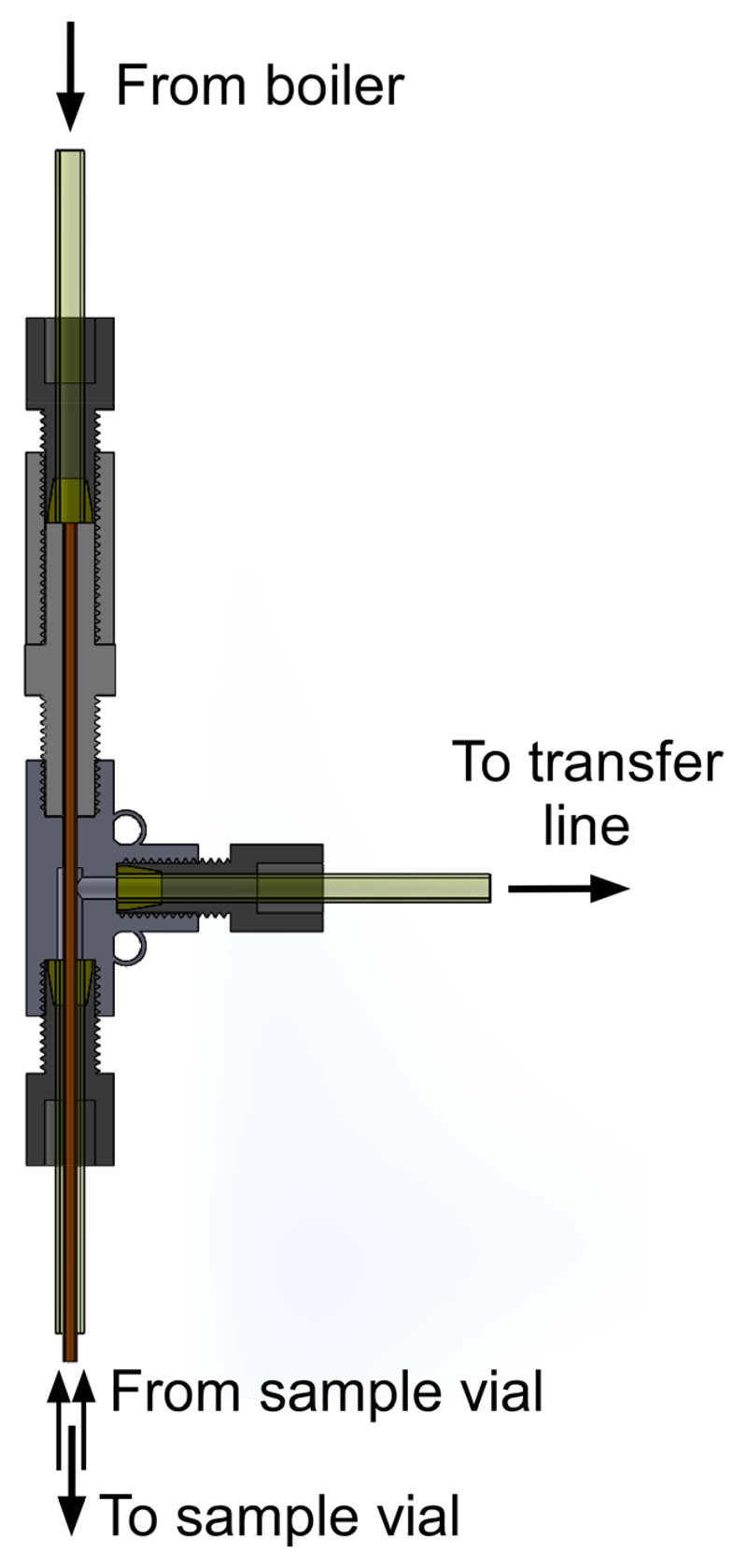
A modified version of the fluid path developed for the SPINlab™ was used for performing dissolution DNP experiments. All parts that are inserted inside the cryostat, namely the sample vial, the inner and outer lumens, as well as the dynamic seal, were unmodified. The dissolution syringe was replaced by the 7 mL stainless steel water boiler described in an earlier publication18, and two pneumatically-controlled diaphragm-sealed valves were used to control the output of the boiler as well as the input of helium gas to pressurize and push the dissolution water through the fluid path. The boiler was connected to the inner lumen through a 100 mm-long PEEK tube (1/8-in outer diameter and 1/16-in inner diameter) connected to a flow separator (see Fig.3) required to seal the fluid path assembly and redirect the outflow of hyperpolarized solution into a receiver vessel (20 mL Falcon tube) through a transfer line terminated with a one-way valve to avoid any backflow or cryo pumping into the fluid path. The flow separator is based on a commercial PEEK 1/16-in tee connector (P-712, IDEX-HS, USA) through which the inner lumen is tightly fitted and glued (Dymax 1121-M UV curing glue). A polychlorotrifluoroethylene (PCTFE) male union part (P-645, IDEX-HS, USA) was used to connect the boiler output tube to the tee connector. In the specific implementation presented in this manuscript, a single boiler was used for performing the dissolution of the two separate samples loaded in the polarizer. The two dissolutions were performed sequentially, as detailed below.
Figure 3.
Flow separator of custom-designed fluid path used for dissolution.
Sample Preparation
100 μL of neat [1-13C]pyruvic acid (Cambridge Isotope Laboratory, Cambridge, USA) doped with 25 mM trityl radicals (AH111501, GE Healthcare, USA) was loaded into each sample vial of two modified fluid paths. After a helium gas purge and a leak test procedure, each fluid path was loaded inside one of the two sample access tubes of the DNP insert. To prevent air from contaminating the cryostat, a purge and pressurization of the access tubes was performed using a pumping line and He gas prior to opening the gate valves. The two vials were sequentially lowered from the top flange into the microwave cavity using a three-step process: the vial was first lowered to the level of the 50-K plate; after 5 min, it was further lowered to the level of the 3-K plate; 5 min later, it was gradually lowered inside the cavity at its final position. The typical time for the complete insertion of the fluid paths was 20 min.
Solid-state DNP and 13C polarization measurement
The optimal microwave frequency for DNP was determined by acquiring the 13C MR signal after 3 h of microwave irradiation at a series of frequencies separated by 0.01 GHz around the central frequency of the microwave source with a microwave power of 45 mW. The optimal power was consecutively determined by recording the 13C signal intensity after 15 min of irradiation at the optimal frequency from 5 to 45 mW by step of 5 mW. The 13C polarization build-up was monitored by applying a 15° RF pulse every 10 min. The maximum solid-state 13C polarization was determined by comparing the 13C MR signal recorded following a 90° RF pulse applied both after 3 h of polarization at the optimal microwave frequency and power and after fully saturating the spin system and a 30-h magnetization recovery period without microwave irradiation.
Dissolution and liquid-state 13C polarization measurement
5 mL of deionized water containing 100 mg/L ethylenediaminetetraacetic acid disodium (EDTA-Na2) was preloaded into the boiler and heated to 130±5°C prior to each dissolution. Dissolution of each DNP-enhanced [1-13C]pyruvic acid sample was initiated by pulling the vial 100 mm above the magnet isocenter. Once the vial was in position, a two 2-way stopcock fitted to the tee connector was manually opened and a computer-controlled sequence triggered by a hardware switch released the superheated solvent followed by opening the diaphragm valve to start the flow of He gas 0.8 s later (6 bar for 5 s) through the boiler into the fluid path. The resulting solution was collected inside a 20-mL Falcon tube preloaded with 3 mL of an aqueous buffer solution (470 mM NaOH and 260 mM Tris) to balance the pH of the hyperpolarized solution to around 7.5. At the end of the dissolution, the fluid path was rapidly pulled back to bring the sample vial into the airlock that is located in the room-temperature/top part of the insert before closing the gate valve. An aliquot of 600 μL of the hyperpolarized solution was transferred through a Polytetrafluoroethylene (PTFE) capillary tube into a 5-mm diameter MR tube preloaded inside a shielded 600-MHz MR magnet (Bruker, Rheinstetten, Germany) located 3 m away from the polarizer. The liquid-state 13C MR acquisition started 26 s after dissolution and a series of single-shot 13C spectra were recorded by applying a 10° RF pulse every 3.3 s for 5 min. Finally, the room-temperature thermal equilibrium 13C signal was measured after having added 6 μL of Dotarem (1 mM Gd-DOTA) to the 600 μL aliquot (1024 scans with a repetition time of 30 s). The thermal equilibrium signal was compared to the first hyperpolarized 13C MR acquisition to compute the liquid-state 13C polarization 26 s after dissolution.
Results
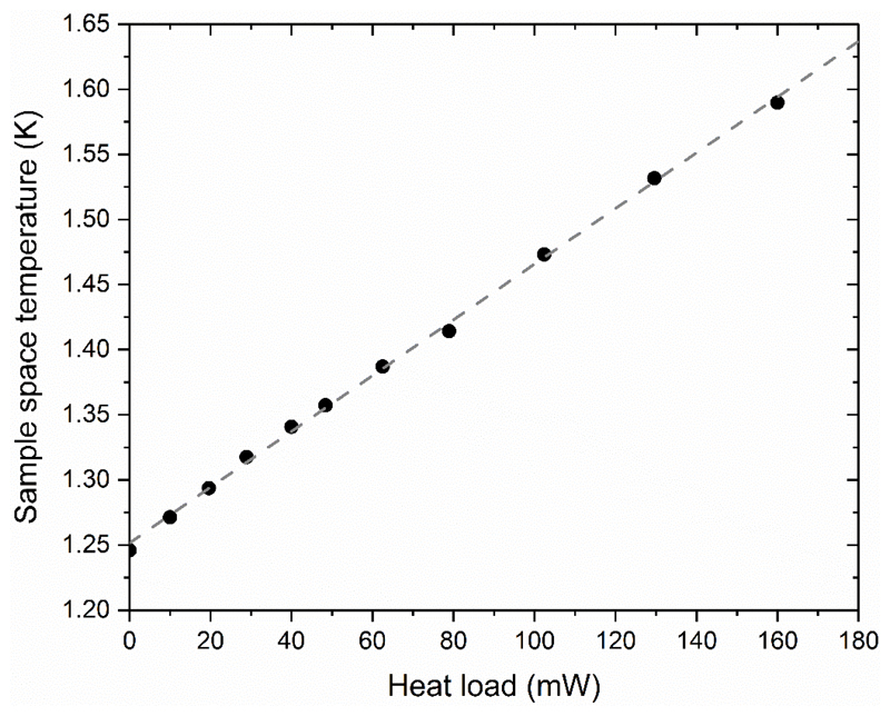
With the test insert in place, the bath temperature inside the sample space stabilizes at 1.25 ±0.01 K (corrected for the magnetoresistance induced by the 7 T field). When the heater of the test insert is switched on, the temperature rises at a rate of 2.14 mK/mW (see Fig.4). The base temperature with the DNP insert is 1.35±0.01 K, which according to data presented in Fig.4 corresponds to an extra heat load of about 50 mW.
Figure 4.
Sample space temperature as a function of the heating power dissipated by the 100-Ω resistor attached to the test insert and immersed in the 85 mL helium bath of the sample space. Note that the field in the superconducting magnet was set to 7 T.
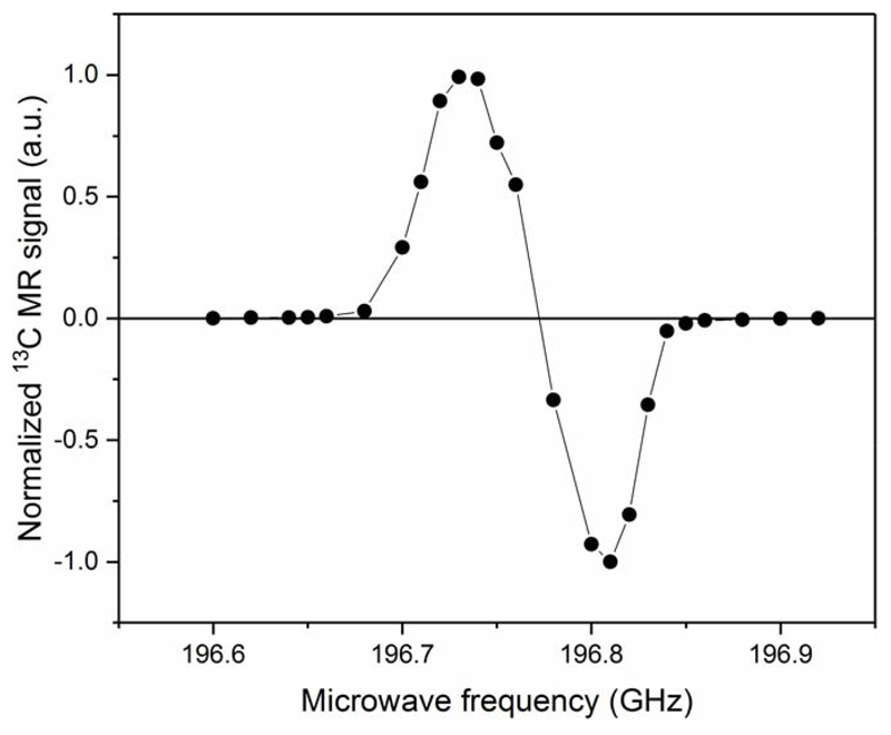
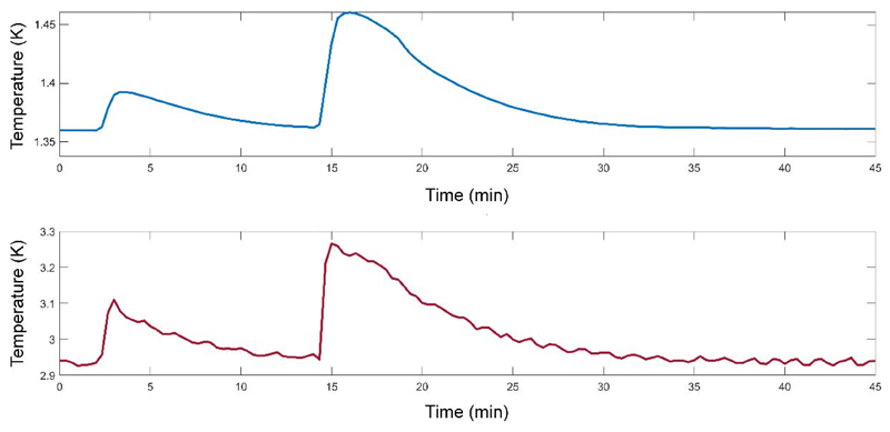
The microwave spectrum obtained from the microwave sweep performed on the [1-13C] pyruvic acid sample is shown in Fig.5. The shape of the spectrum is in good agreement with the data previously reported on similar samples measured at 1 K and 6.7 T or 7 T20,21. The maximum positive solid-state 13C polarization, deduced from the theoretical 13C polarization at 7 T and 1.35 K (0.133%) and the solid-state 13C NMR signal enhancement (375±40) measured at 196.7113 GHz with 20 mW, was 50±5% with a build-up time constant of 2000±200 s. This value was confirmed by the liquid-state 13C polarization measured 26 s after dissolution in the 600 MHz spectrometer (Fig.6), where we obtained 36±2%, which can be back-extrapolated to 55±5% at the time of dissolution if we assume a low-field relaxation time constant of 60 s during transfer from the polarizer into the 600 MHz magnet. A 13C T1 of 45±1 s was deduced from the decay curve measured inside the bore of the 600 MHz magnet after correction for the effect of the RF pulses. Two consecutive dissolutions were performed within 12 min and each dissolution led to a transient temperature increase of both the sample space and the 3-K plate (see Fig.7). The 3-K plate temperature went up to 3.3 K from its steady-state value of 2.9±0.1 K and the sample space temperature peaked at around 1.45 K during the second dissolution. Both temperatures returned to their steady-state levels within 15 min.
Figure 5.
Microwave spectrum measured in a [1-13C]pyruvic acid sample doped with 25 trityl radical (AH 111 501) at 7 T and 1.35 K. Each data point has been recorded after 3 h of DNP, when the 13C polarization had reached a plateau. The solid line connecting the data points only serves as guide for the eyes.
Figure 6.
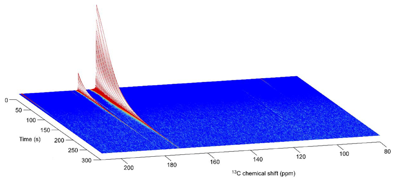
Series of liquid-state 13C spectra recorded in a 600-MHz spectrometer on a 80 mM hyperpolarized [1-13C]pyruvate sample (pH 7.2) inside a 5-mm MR tube. Acquisition was initiated 26 s after dissolution and the repetition time was set to 3.3 s with a flip angle of 10°. The two most intense peaks at 173 ppm and 181.6 ppm correspond to [1-13C]pyruvate and [1-13C]pyruvate hydrate, respectively. The natural abundance [2-13C]pyruvate and [2-13C]pyruvate hydrate were also observed at 207.8 ppm and 96.5 ppm, respectively.
Figure 7.
Temperature evolution of the 3-K (red line) and 1-K (blue line) plates during two consecutive dissolutions experiments initiated at t0 and t = t0 +12 min, respectively.
Discussion
Although zero boil-off “wet” magnets are now standard in MR, thanks to the technological advances of cryocooler that can be taken advantage of for re-condensing evaporated helium, recently developed conduction-cooled superconducting dry magnets provide an attractive option to simplify DNP polarizers and completely remove the need for the input of liquid helium. The recent DNP polarizer designs include a high-field (9.4 T or 10.1 T) dry magnet15,16. The design presented herein displays how a conduction-cooled 7 T magnet was anchored to the 1-K plate, the temperature of which always stays below 3 K during standard operation therefore minimizing the risk of an accidental quench. The choice of the field strength was motivated by the previously reported large 13C polarization obtained at 7 T21–23.
As specified above, the magnet is operated in a non-persistent mode. For DNP experiments, the stability of a good-quality power supply is sufficient. Using the test insert, we determined that when the field is ramped from 0 to 7 T, the base temperature increases from 1.2 K to 1.25 K. Using the linear fit from Fig.4, it can be deduced that the non-persistent magnet charges the 1-K closed-cycle helium recirculation system with an extra 25 mW heat load.
With the DNP insert and the field set at 7 T, the base temperature of the 85 mL liquid He bath is 1.35 K. Again using the results presented in Fig.4, this increase of 100 mK as compared to the test insert at the same field roughly corresponds to a heat load of 50 mW from the insert. To reduce the working temperature, it could be desirable to implement an optimized DNP insert with better thermal anchorage at the 50-K and 3-K plates to reduce the heat load on the 1-K plate. But for a more prominent reduction of the base temperature, a booster pump could be added into the 1-K closed-cycle helium recirculation system.
In terms of cryogenic performance, the continuous cooling efficiency of the herein described cryostat is similar to the transitory cooling efficiency of a single-shot pumped-bath cryostat. However, the 1-K closed-cycle helium recirculation can be driven out of its thermodynamic steady-state by a large abrupt heat load into the sample space, such as the introduction of a large amount of warm helium gas, air, or aqueous solution leaking from the dissolution apparatus. For this reason, the dissolution method used in the original design10 would be difficult if not impossible to implement in this system without risking evaporating the entire volume of liquid helium condensed inside the 1-K pot and critically warming up the 1-K plate. To perform dissolution DNP experiments, it was therefore decided to use self-contained fluid paths, which are helium-leak-tight assemblies that can be inserted into the cryostat through a hermetically-sealed feedthrough. Although the fluid path technology was originally designed for human experiments, where it is vital that the sample remains behind an environmental barrier13, it is indeed also attractive for cryogen-free DNP system since it negates the needs for pressurizing the sample space to atmospheric pressure prior to the introduction of a dissolution insert. The fluid path approach was previously used for one of the two reported cryogen-free DNP system15.
Thanks to the axial symmetry of the DNP insert, each vial is placed at an identical position with respect to the waveguide and the DNP efficiency is therefore independent of the channel in which the sample is loaded. In the herein presented experiments, the delay between two dissolutions was set to 12 min which was long enough for the system to nearly recover its base temperature. The temperature of the 1-K plate increased by about 50 mK during the first dissolution before relaxing back to its steady-state value within about 10 min. It can be therefore deduced by a crude integration that the average temperature was 25 mK above steady state during 10 min. Using the linear fit from Fig.4, this means an average heat load for the 1-K plate of 12.5 mW during 10 min, i.e. 7.5 J of heat dissipated into the 1-K plate. This is comparable to the less than 70 J measured during a dissolution inside a fluid path used in the SPINlab™ if we consider that the tests presented here used 5 mL of dissolution solvent and a push time of 4 s instead of 40 mL of superheated water13 pushed for approximately 10 s. It is shown in Fig.7 that the 3-K plate also dissipates a significant portion of the heat-load from the dissolution though this is actively discharged by the cryocooler. The fact that the temperature jumped to a higher value during the second dissolution also shows that some of the heat had dissipated elsewhere in the cryostat and that the system had not fully recovered its steady state 12 min after the first dissolution. This is borne out by the fact that the flow to the 1K pot had not recovered to equilibrium levels before the second dissolution took place. The delay between dissolution could nevertheless probably be further reduced without driving the 1-K closed-cycle helium recirculation out of its thermodynamic steady-state, but the heat load on the 1-K plate can most likely be minimized by improving thermal anchorage at the 50-K and 3-K plates as mentioned above. The fact that the flow through the 1-K closed-cycle remains well below the limits of the system with the heat loads during a dissolution means that it should be possible to perform back-to-back dissolutions, if needed.
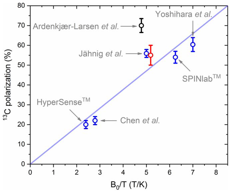
In terms of DNP performance, the liquid-state 13C polarization obtained with this 7-T/1.35-K polarizer seems to be in good agreement with the extrapolation of the previously published data adjusted for magnetic field and temperature if we assume that, as was highlighted by Comment et al.18. The maximum 13C signal enhancement that can be obtained using a given radical is indeed independent of B0/T, from which it follows an approximate linear behavior of the 13C polarization within the operating window of current hyperpolarizers (see Fig.8). This rule of thumb seems to hold for most data obtained with the standard trityl-doped [1-13C]pyruvic acid samples (without any Gd-doping of the sample)21,23,24, except for the recently published values obtained by Ardenkjaer-Larsen et al. using a 6.7-T/1.4-K cryogen-free polarizer15.
Figure 8.
Liquid-state 13C polarization of [1-13C]pyruvate obtained from hyperpolarized [1-13C]pyruvic acid (neat) doped with trityl radical (15 mM - 26 mM) as a function of B0/T, back-calculated to the time of the dissolution. Five data points (blue circles) were used for the linear fit (least square method) shown in blue: (1) estimated mean 13C polarization obtained with HyperSense™ (3.35 T, 1.4 K); (2) reported 13C polarization obtained using the original hyperpolarizer by Chen et al. (3.35 T, 1.2 K)25; (3) estimated mean 13C polarization obtained with SPINlab™ (5 T, 0.8 K); (4) reported 13C polarization obtained by Yoshihara et al. (7 T, 1 K)21; (5) reported 13C polarization obtained by Jähnig et al. (7 T, 1.4 K)23. Two additional data points are displayed: (black circle) reported 13C polarization obtained by Ardenkjaer-Larsen et al. (6.7 T, 1.4 K)15; (red circle) 13C polarization reported in the present work (7 T, 1.35 K).
In conclusion, the herein described zero boil-off polarizer is an alternative to other DNP systems for in vitro or preclinical hyperpolarized MR studies. This particular system is built around a fully automated cryogenic design based on a commercial dilution refrigerator that does not require any mechanical adjustment. Its temperature is therefore highly stable over extended periods of time (up to several months) since no adjustment of the input flow into the 1-K pot has to be made. Additionally, like the SPINlab™ and a previously described home-made system13,25, it can polarized several samples (2-4) in parallel.
Acknowledgements
We would like to thank Dr. Oleksandr Usenko for his kind technical help.
Funding information
This work is part of a project that has received funding from the European Union’s Horizon 2020 European Research Council (ERC Consolidator Grant) under grant agreement No 682574 (ASSIMILES).
Abbreviations used
- DNP
Dynamic nuclear polarization
- MR
Magnetic resonance
- ESR
Electron spin resonance
- STP
standard temperature and pressure
- PLA
Polylactic acid
- PCB
printed circuit board
- PEEK
polyether ether ketone
- RF
Radiofrequency
- PCTFE
Polychlorotrifluoroethylene
- EDTA
Ethylenediaminetetraacetic acid
- PTFE
Polytetrafluoroethylene
References
- 1.Ardenkjaer-Larsen JH, Boebinger GS, Comment A, et al. Facing and Overcoming Sensitivity Challenges in Biomolecular NMR Spectroscopy. Angew Chem Int Ed Engl. 2015;54:9162–9185. doi: 10.1002/anie.201410653. [DOI] [PMC free article] [PubMed] [Google Scholar]
- 2.Ardenkjaer-Larsen JH, Fridlund B, Gram A, et al. Increase in signal-to-noise ratio of > 10,000 times in liquid-state NMR. Proc Natl Acad Sci USA. 2003;100:10158–10163. doi: 10.1073/pnas.1733835100. [DOI] [PMC free article] [PubMed] [Google Scholar]
- 3.Comment A. Dissolution DNP for in vivo preclinical studies. J Magn Reson. 2016;264:39–48. doi: 10.1016/j.jmr.2015.12.027. [DOI] [PubMed] [Google Scholar]
- 4.Comment A, Merritt ME. Hyperpolarized Magnetic Resonance as a Sensitive Detector of Metabolic Function. Bioch. 2014;53:7333–7357. doi: 10.1021/bi501225t. [DOI] [PMC free article] [PubMed] [Google Scholar]
- 5.Kurhanewicz J, Vigneron DB, Ardenkjaer-Larsen JH, et al. Hyperpolarized C-13 MRI: Path to Clinical Translation in Oncology. Neoplasia. 2019;21:1–16. doi: 10.1016/j.neo.2018.09.006. [DOI] [PMC free article] [PubMed] [Google Scholar]
- 6.Marco-Rius I, Comment A. In Vivo Hyperpolarized 13C MRS and MRI Applications. eMagRes. 2018;7:167–178. [Google Scholar]
- 7.Ardenkjaer-Larsen JH, Macholl S, Johannesson H. Dynamic nuclear polarization with trityls at 1.2 K. Appl Magn Reson. 2008;34:509–522. [Google Scholar]
- 8.Eichhorn TR, Takado Y, Salameh N, et al. Hyperpolarization without persistent radicals for in vivo real-time metabolic imaging. Proc Natl Acad Sci USA. 2013;110:18064–18069. doi: 10.1073/pnas.1314928110. [DOI] [PMC free article] [PubMed] [Google Scholar]
- 9.Capozzi A, Cheng T, Boero G, Roussel C, Comment A. Thermal annihilation of photo-induced radicals following dynamic nuclear polarization to produce transportable frozen hyperpolarized 13C-substrates. Nat Commun. 2017;8 doi: 10.1038/ncomms15757. 15757. [DOI] [PMC free article] [PubMed] [Google Scholar]
- 10.Wolber J, Ellner F, Fridlund B, et al. Generating highly polarized nuclear spins in solution using dynamic nuclear polarization. Nucl Instrum Meth A. 2004;526:173–181. [Google Scholar]
- 11.Radebaugh R. Cryocoolers: the state of the art and recent developments. J Phys-Condens Mat. 2009;21 doi: 10.1088/0953-8984/21/16/164219. 164219. [DOI] [PubMed] [Google Scholar]
- 12.Piegsa FM, van den Brandt B, Kirch K. High-power closed-cycle 4He cryostat with top-loading sample exchange. Cryogenics. 2017;87:24–28. [Google Scholar]
- 13.Ardenkjaer-Larsen JH, Leach AM, Clarke N, Urbahn J, Anderson D, Skloss TW. Dynamic Nuclear Polarization Polarizer for Sterile Use Intent. NMR Biomed. 2011;24:927–932. doi: 10.1002/nbm.1682. [DOI] [PubMed] [Google Scholar]
- 14.Shvets AD. Production of temperatures below 1° K by pumping on liquid helium-4. Cryogenics. 1966;6:270–274. [Google Scholar]
- 15.Ardenkjaer-Larsen JH, Bowen S, Petersen JR, et al. Cryogen-free dissolution dynamic nuclear polarization polarizer operating at 3.35 T, 6.70 T, and 10.1 T. Magn Reson Med. 2019;81:2184–2194. doi: 10.1002/mrm.27537. [DOI] [PubMed] [Google Scholar]
- 16.Baudin M, Vuichoud B, Bornet A, Bodenhausen G, Jannin S. A Cryogen-Consumption-Free System for Dynamic Nuclear Polarization at 9.4 T. J Magn Reson. 2018;294:115–121. doi: 10.1016/j.jmr.2018.07.001. [DOI] [PubMed] [Google Scholar]
- 17.Uhlig K. Dry dilution refrigerator with He-4-1 K-loop. Cryogenics. 2015;66:6–12. [Google Scholar]
- 18.Comment A, van den Brandt B, Uffmann K, et al. Design and performance of a DNP prepolarizer coupled to a rodent MRI scanner. Concepts Magn Reson B. 2007;31:255–269. [Google Scholar]
- 19.Comment A, van den Brandt B, Uffmann K, et al. Principles of operation of a DNP prepolarizer coupled to a rodent MRI scanner. Appl Magn Reson. 2008;34:313–319. [Google Scholar]
- 20.Capozzi A, Patel S, Wenckebach WT, Karlsson M, Lerche MH, Ardenkjær-Larsen JH. Gadolinium Effect at High-Magnetic-Field DNP: 70% 13C Polarization of [U-13C] Glucose Using Trityl. J Phys Chem Lett. 2019;10:3420–3425. doi: 10.1021/acs.jpclett.9b01306. [DOI] [PubMed] [Google Scholar]
- 21.Yoshihara HAI, Can E, Karlsson M, Lerche MH, Schwitter J, Comment A. High-field dissolution dynamic nuclear polarization of [1-13C]pyruvic acid. Phys Chem Chem Phys. 2016;18:12409–12413. doi: 10.1039/c6cp00589f. [DOI] [PubMed] [Google Scholar]
- 22.Cheng T, Capozzi A, Takado Y, Balzan R, Comment A. Over 35% liquid-state 13C polarization obtained via dissolution dynamic nuclear polarization at 7 T and 1 K using ubiquitous nitroxyl radicals. Phys Chem Chem Phys. 2013;15:20819–20822. doi: 10.1039/c3cp53022a. [DOI] [PubMed] [Google Scholar]
- 23.Jähnig F, Kwiatkowski G, Däpp A, et al. Dissolution DNP using trityl radicals at 7 T field. Phys Chem Chem Phys. 2017;19:19196–19204. doi: 10.1039/c7cp03633g. [DOI] [PubMed] [Google Scholar]
- 24.Chen AP, Albers MJ, Cunningham CH, et al. Hyperpolarized C-13 spectroscopic imaging of the TRAMP mouse at 3T—Initial experience. Magn Reson Med. 2007;58:1099–1106. doi: 10.1002/mrm.21256. [DOI] [PubMed] [Google Scholar]
- 25.Batel M, Krajewski M, Weiss K, et al. A multi-sample 94 GHz dissolution dynamic-nuclear-polarization system. J Magn Reson. 2012;214:166–174. doi: 10.1016/j.jmr.2011.11.002. [DOI] [PubMed] [Google Scholar]


