Abstract
Surgical evaluation of medically refractory epilepsy frequently necessitates implantation of multiple intracranial electrodes for the identification of the seizure focus. Knowledge of the individual brain’s surface anatomy and deep structures is crucial for planning the electrode implantation. We present a novel method of 3D printing a brain that allows for the simulation of placement of all types of intracranial electrodes. We used a DICOM dataset of a T1-weighted 3D-FSPGR brain MRI from one subject. The segmentation tools of Materialise Mimics 21.0 were used to remove the osseous anatomy from brain parenchyma. Materialise 3-matic 13.0 was then utilized in order to transform the cortex of the segmented brain parenchyma into a mesh-like surface. Using 3-matic tools, the model was modified to incorporate deep brain structures and create an opening in the medial aspect. The final model was then 3D printed as a cerebral hemisphere with nylon material using selective laser sintering technology. The final model was light and durable and reflected accurate details of the surface anatomy and some deep structures. Additionally, standard surgical depth electrodes could be passed through the model to reach deep structures without damaging the model. This novel 3D-printed brain model provides a unique combination of visualizing both the surface anatomy and deep structures through the mesh-like surface while allowing repeated needle insertions. This relatively low-cost technique can be implemented for interdisciplinary preprocedural planning in patients requiring intracranial EEG monitoring and for any intervention that requires needle insertion into a solid organ with unique anatomy and internal targets.
Keywords: 3D printing, Deep electrode, Brain surface anatomy, Epilepsy, EEG
Introduction
The advent of 3D printing technology has dramatically enhanced how human anatomy is viewed in clinical medicine. In recent years, the emergence of 3D printing highly detailed organ models, derived from imaging, has helped many medical specialties provide more personalized care. A systematic review of 3D printing techniques in clinical medicine in 2016 showed that 3D printing is well integrated into surgical planning and research [1]. True-size 3D models have been shown to help surgeons engage in accurate preoperative planning of various procedures including craniomaxillofacial reconstruction [2, 3], intracranial aneurysm repair [4], living donor liver transplantation [5], and various orthopedic surgeries [6, 7]. Of note, starting July of this year, CPT category III codes will include 3D-printed anatomic models [8]. The incorporation of these personalized patient-specific 3D models into preoperative planning can therefore improve intraoperative surgical techniques, provide better training for residents, shorten the time spent in the operating room, aid in patient education, and ultimately improve patient outcome.
Scalp EEG is often used as the first and only step of characterizing seizures [9, 10]. Refractory epilepsy refers to seizures that cannot be fully controlled using medications. When accurate localization of the seizure focus is needed for surgical evaluation of refractory epilepsy, scalp EEG is often insufficient, especially in non-lesional epilepsy [11, 12]. This necessitates invasive recording by implantation of intracranial electrodes. To test hypothesis on localization, an interdisciplinary team that includes the neurologist, neuropsychologist, radiologist, and neurosurgeon plan the implantation targets from imaging, non-invasive electrophysiology, and neuropsychological evaluations [13].
Despite the increasing use of advanced computer visualization and surgical robotics, the implantation procedure needs critical decision-making by an experienced neurosurgeon using the identification of patient-specific brain surface landmarks including gyral/sulcal morphology and nearby arterial and venous structures. We demonstrate the feasibility of using a 3D-printed mesh-like cerebral cortex. This not only allows for visualization of the surface anatomy, but also enables partial visualization of key deep brain structures, while allowing repeated placement of intracranial electroencephalography (iEEG) implants, including depth and subdural electrodes. Here, we present a novel method of 3D printing a brain that allows for the simulation of placement of all types of intracranial electrodes. To our knowledge, the use of a mesh-like 3D-printed brain model has not previously been described in the literature.
Methods
An Institutional Review Board (IRB) approval was not required for this study because the production of model was retrospective and technical in nature, and the model was not directly used in patient care. In addition, the development of the 3D-printed mesh-like cortex, including segmentation and modification steps, was realized through the collaboration of an engineer from Materialise and a neuroradiologist through screen sharing in each and every step of the process.
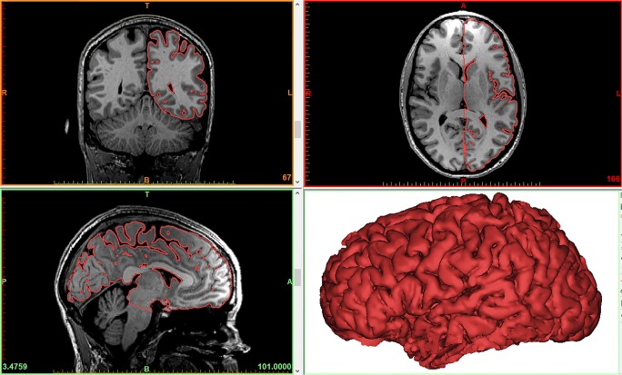
Initially, T1-weighted 3D fast spoiled gradient echo (FSPGR) images of a magnetic resonance imaging (MRI) of a healthy subject’s brain were acquired in Digital Imaging and Communications in Medicine (DICOM) format with 1-mm thickness as part of a functional MRI dataset. A Siemens MAGNETOM Skyra 3T scanner was used. These images were imported in Materialise Mimics Medical 20.0 where the brain parenchyma was segmented and converted to a STL file. More specifically, the “Dynamic Region Grow” tool was used to create an initial segmentation of the brain. Then, the “Split Mask” tool was used to remove any osseous and/or venous areas from the segmentation. Finally, the segmentation was converted in an STL file, and the “Trim” tool from Materialise 3-matic Medical 12.0 was used to cut the brain model through the interhemispheric fissure, to eliminate one hemisphere, allowing visualization of the medial aspect of the remaining hemisphere (Fig. 1).
Fig. 1.
The resulting model of the brain parenchyma based on the Mimics segmentation process. The surface contour of the model is overlaid on the 2D image data to provide a visualization of the segmentation quality
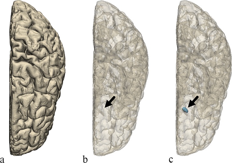
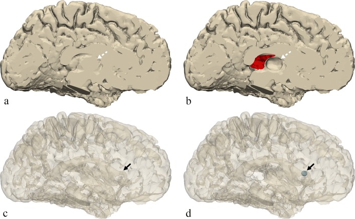
Once the model of the brain was created, a few changes were made to represent certain anatomical structures that were not readily apparent on the model using Materialise 3-matic 12.0 (Materialise NV, Leuven, Belgium). First, a small elliptical structure was created to represent the position of the caudate head adjacent to the frontal horn of the lateral ventricle. From the medial side of the model, an area of the brain surface was indented to represent the position and shape of the thalamus. Finally, a portion of the medial surface of the brain representing the septum pellucidum was removed from the model creating a hole on the inner surface of the brain which would allow for direct viewing of internal structures and removal of support material during post-processing after completion of the 3D printing (Figs. 2 and 3).
Fig. 2.
Top view of the brain. a The original model. b The original model transparent. c The final model transparent. The final model includes the small region created to represent the position of the caudate head (arrow)
Fig. 3.
Medial view of the brain. a The original model. b The final model. c The original model transparent. d The final model transparent. The final model includes the small region created to represent the position of the caudate head (solid black arrow), an indented area representing the thalamus (dotted white arrow), and a portion of the surface removed representing the position of the septum pellucidum, a hole through which the inside of the model can be seen (outlined with a black line)
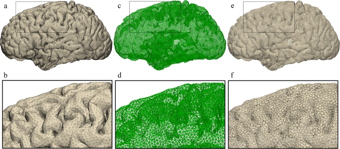
Once the model geometry was finalized, the brain model surface was remeshed using the “Uniform Remesh” tool in Materialise 3-matic creating a surface triangulation of approximately equilateral triangles with a target triangle edge length of 2.375 mm (Fig. 4). To ensure that the holes in the printed model were large enough to allow passage of electrodes, the brain model was scaled up by a factor of 1.5. This resulted in an approximate triangle edge length of 4 mm. Next, we converted the surface triangulation of the brain model into a “Light Weight Structures” graph set using the “Create Part Graph” tool (Fig. 5). This tool acquires the triangle edges and creates graphs (i.e., lines) that match the edges. Finally, the graphs (i.e., lines) were given diameter of approximately 1 mm by using the “Convert Graph to STL” tool (Fig. 5). Once the triangle edges were converted into lightweight structures with a diameter of 1 mm, the resulting holes between the lightweight structures making up the surface were about 2 mm across.
Fig. 4.
Uniform triangulation process. a, b Superior and lateral views of the brain model showing the model’s initial random triangulation. c, d The model’s superior and lateral views resulting uniform triangulation
Fig. 5.
Graph creation and STL conversion. a, b Lateral view of the model having undergone uniform triangulation with detailed view of surface. c, d The surface triangulation edges are converted to graphs with a detailed view. e, f Conversion of the graphs into 1 mm diameter allows creation of the STL file with its detailed view
When the porous model design was completed, the model was 3D printed using a selective laser sintering (SLS) machine and polyamide nylon powder using the medical-grade commercial 3D printing services of Materialise. The model was printed on an EOSINT P730 laser sintering machine manufactured by EOS (Munich, Germany). After completion of printing, the model was removed from the build area and the excess powder was cleared from the model through the previously described defect/window at the location of the septum pellucidum.
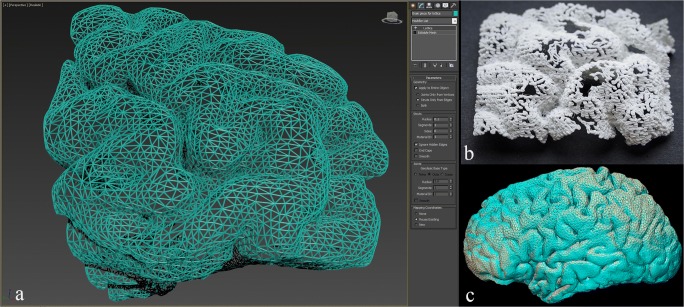
Another method for creating a mesh-like surface is through Autodesk 3D Studio Max. This may be accomplished by using the “Lattice” tool found under the “Object-Space Modifiers” heading of the “Modifier List” within the “Modify” panel. The “Lattice” modifier converts the edges of surface polygons of a mesh into cylindrical struts and/or the vertices into joint polyhedra. In our case, the former setting was chosen, i.e., the “Struts Only from Edges” with a radius of 0.1 cm. The number of segments and the diameter of the cylinders can be defined, as can the size and shape of the joints, if needed. However, this tool alone would not be enough to achieve the goal of designing a desirable surface mesh since the 3D-reconstructed STL of the brain consists of a very high number of surface triangles; therefore, an initial step of decreasing the number of polygons/triangles may be performed beforehand. In Autodesk 3D Studio Max, this can be performed through the optimization modifiers, which include preferably “ProOptimizer” as well as “MultiRes” and “Optimize” tools. In this step, an ideal balance between surface detail/definition and the desired density of polygons/vertices must be taken into consideration. A sample piece of the frontal lobe is shown upon completion of the aforementioned digital manipulation (Fig. 6a), which was 3D printed using a more widely available and less expensive 3D printing technique, i.e., fused deposition modeling (FDM). A Stratasys F170 machine was implemented using printing material of ABS-M30 and dissolvable QSR support material with a layer thickness of 0.178 mm and accuracy of ± 0.200 mm.
Fig. 6.
Brain mesh piece. a A portion of the frontal lobe cortex is demonstrated and converted into a mesh wire structure utilizing the lattice modifier in Autodesk 3D Studio Max (settings: struts only created from the edges excluding the vertices, radius = 0.1 cm, segments = 1, sides = 6). b Attempted 3D printing using heat extrusion. c Superimposition of the 3D reconstruction of the CT scanned 3D printed model onto the original STL file
Results
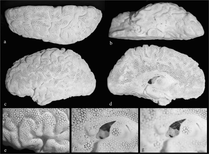
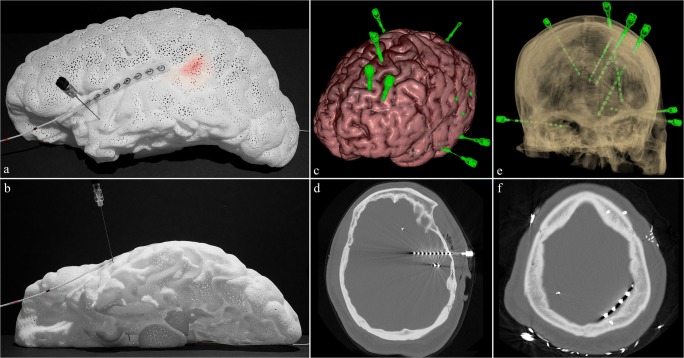
The final polyamide model (Fig. 7) is lightweight (140 g), relatively durable, and white in color. Passage of a spinal needle to simulate implantation of a deep iEEG electrode is demonstrated (Fig. 8a, b). The tip of the needle can be visualized extending just beyond the amygdala (Fig. 8b). In addition, a subdural lead (strip) is shown overlying the left superior temporal gyrus (Fig. 8a, b). Lastly, a light-emitting diode (LED) strip measuring 3 × 30 mm in size is passed through the septum pellucidum opening in the medial aspect and placed beneath the surface in the region of Wernicke’s based on findings on a functional MRI, located at the posterior aspect of the left superior temporal sulcus (Fig. 8a). As noted in a real-life example case (Fig. 8c–f), multiple electrodes are placed at a time. The cost of the model was just under $500 when the medical-grade commercial 3D printing services of Materialise were used. Upon close inspection of the mesh structure, the holes demonstrate a triangular shape (Fig. 7d), which allow for the passage of a deep EEG electrode of up to 2 mm in diameter.
Fig. 7.
Final 3D printed brain model. a Showing superior view. b Inferior view. c Lateral view. d Medial view. e Anatomic landmark in the shape of capital letter “M” is identified in the inferior frontal gyrus in the region of Broca’s activation consisting of pars orbitalis, pars triangularis, and pars opercularis. Visualization of the interior of the model through the opening at the site of septum pellucidum is demonstrated with camera focus on the surface (f) and on the deep structures (g). The medially indented designated location of the thalamus is noted just posterior to the opening
Fig. 8.
Demonstration of intracranial EEG lead placement. a, b Lateral and inferior views showing passage of spinal needle through the temporal lobe simulating placement of a depth electrode with the tip visualized extending just beyond the amygdala; a subdural lead overlying the superior left temporal gyrus and the Wernicke’s location at the posterior aspect of the left superior temporal sulcus based on fMRI is lit in red by light-emitting diode (LED) strip under the surface. c An example of multiple intracranial depth electrodes placed in a patient shown through brain 3D surface reconstruction from MRI fused with 3D reconstructed depth electrodes from CT data (created using Surgical Theater). d A temporal approach depth electrode reaching the amygdala shown on axial CT bone window. e Transparent 3D surface reconstruction of the calvarium and depth electrodes from CT (created using Surgical Theater). f Subdural lead (strip) overlying the left parietal lobe shown on axial CT bone window
The gyral and sulcal anatomy of the brain is fully detectable on the lateral and superior aspects. The medial and inferior portions lose some detail due to the innate suboptimal and imperfect segmentation of these parts being either too small or too close to surrounding structures, such as the floor of the anterior cranial fossa (Fig. 8b) or the other cerebral hemisphere. Since the entire model is white in color, visualization of the interior is somewhat difficult through the surface, which has numerous very small holes. However, the defect through the site of the septum pellucidum provides a small window (Fig. 7f, g) to visualize the walls of the lateral ventricle and the graphically added caudate head. The designated site of the thalamus where an indentation is created in the medial aspect of the model is easily recognizable (Fig. 7d), which in turn indicates the location of the subthalamic nuclei. The inferior extent of the model reaches the level of the midbrain (Fig. 7b), but it does not contain the remainder of the brainstem or the cerebellum. As mentioned earlier, the 3D printing technique of FDM was attempted in search of a less expensive alternative. However, the results were unsatisfactory (Fig. 6b).
Discussion
We presented a novel approach in the 3D representation of detailed brain surface anatomy that allows simulation and surgical planning. The 3D model has a mesh-like structure that provides a semi-transparent view of the hemisphere for electrode insertion. It can be created from a standard brain template (generic model), or easily personalized for patient-specific surgical needs. We propose that this type of model can become an effective teaching tool for medical trainees. In its generic form, it can be used in multidisciplinary conferences for planning purposes, and when created as a patient-specific model, can potentially improve surgical planning and interpretation of electrographic data.
The use of 3D printing has been applied in numerous fields of medicine and surgery including neurological and neurosurgical disciplines [4, 14, 15]. The production and utilization of an accurate, flexible, yet durable 3D brain model can provide significant benefits for simulation training and preoperative planning of intracranial electrode implantation, with potential improvement in precise deep brain stimulation electrode placement for epilepsy [16], Parkinson’s disease [17], and other neuropsychiatric conditions. Implantation of intracranial electrodes is a well-established surgical procedure for surgical evaluation of medically refractory seizures, which occur in one-third of all patients with epilepsy [12, 18]. In fact, many studies have shown the positive benefits of iEEG in identifying the exact locations of epileptogenic zones and the precise targeting of sites for epilepsy surgeries leading to favorable postsurgical outcomes [19–24].
The model possesses several unique features. The mesh-like surface structure allows for visualization of deep brain structures and for passing electrodes through the cortex. This can be performed repeatedly, without damaging the model, unlike previous designs of organs in general [25–27], where solid transparent material would surround opaque internal structures. Multidisciplinary preoperative surgical planning and patient consultation can therefore be performed by simulating the accurate placements of electrodes into deep brain structures that may potentially be responsible for refractory epilepsy. Furthermore, the models can be personalized for each patient; thus, the anatomy of the cortex and deep brain structures precisely reflect each patient’s anatomical variation, possibly reducing intraoperative time by reducing the number of intraoperative surgical decisions. This personalized nature can also allow for the optimization of type and length of electrodes, strips, and grids used during surgery, preoperatively instead of intraoperatively, which is the main advantage of using this model.
The size of the holes within the mesh framework and the diameter of the wire mesh components were chosen to allow the best balance between durability, the size of the electrodes used, and the degree of desired visualization of both surface anatomy and deep structures. The model is also lightweight, allowing for ease in handling. After months of use and careful handling in interdisciplinary conferences and by trainees, the model has remained intact. Although various materials could be used to create the model, polyamide nylon was the considered ideal choice of material given its versatility, durability for detailed design, midrange price, lack of need for additional support structures, and the lightweight properties. Other materials have their limitations that made them not suitable for our purposes. Plastic heat extrusion techniques, i.e., FDM, resulted in significantly suboptimal results even when a simplified piece of the brain surface mesh was attempted as shown in Fig. 6b, which later fractured with minimal handling. This optimized test scenario proved that a complete failure would result if attempts were made to print the entire hollow, thin-walled, cerebral hemisphere. Additionally, the printer was unable to preserve the triangular-shaped holes and the struts of the wire mesh structure demonstrated an inaccurate curved appearance. The 3D printer used QRS as a support material, so it can be easily dissolved away when the model is placed in a warm water bath for 2–3 days. For FDM, 3D printers that require mechanical removal of support material, printing such mesh-like structure is not possible due to the high forces required to remove support materials that would destroy the intricate structures. This was demonstrated by attempting to 3D print with a Zortrax M200 machine using ABS material with a layer thickness of 0.09 mm, which was also unsuccessful.
Polyjet technology was ruled out due to the highly involved support removal process, the possibility of model damage during the support removal process, and the low durability of small diameter structures. Stereolithography was ruled out due to the complexity of support removal and the possibility that the support structure attachment points could block the porous structure of the model. Binder Jetting was ruled out due to low durability of small diameter structures. A recently developed method by Hewlett Packard (HP) named Multi Jet Fusion (MJF) uses glue ink and a polyamide powder bed in order to create solid 3D-printed models. This technique is similar to the SLS method used for our model but would provide slightly increased flexibility with a gray color [28]. Based on information currently available for this new technology, it could also be an appropriate technology for this application due to the self-supporting nature of the build technology, the easy removal of excess powder, and the durability of small diameter structures, all similar to laser sintering.
As versatile as this 3D mesh-like brain model is, there are some limitations. The deep brain structures were somewhat more difficult to visualize than expected following the production of the model. In order to alleviate this, a window was created from the medial side in the region of the septum pellucidum to provide better visualization of these structures. The visualization and differentiation of various structures are also made difficult because the polyamide nylon material only comes in white. Differentiation of different structures can be rectified through the use of spray or acrylic paint. Although the model is durable based on the material used, transport can be difficult because it cannot withstand a high degree of compressive forces and therefore ideally a cardboard box filled with polystyrene cushioning material (foam peanuts) should be used for transport. The model’s cost of production was considered midrange compared with most other high-end 3D-printed medical anatomic models; especially compared with those models utilizing the more expensive PolyJet techniques.
An additional limitation is the difficulty in discerning surface anatomy at areas of minimal sulcation. Such areas include the inferior frontal and temporal lobes, where the gyral and sulcal anatomy consists of small structures, such as the olfactory sulcus separating the gyrus rectus from the medial orbital gyrus. These imperfections are due in part to the loss of the deep portions of the sulci in the automatic segmentation step due to their submillimeter diameter, and the inability of the 3D printer to separately print/resolve entities that are too close to one another, i.e., the minimum clearance required. The latter was also a limiting factor in the final shape and size of some holes in the mesh structure. This includes triangles that are smaller than 2 mm in diameter, due to their initial shape being elongated, being lost during printing because the edges are too close to one another. However, due to the preservation of the majority of triangles throughout the model, this is not a practical limitation for implanting electrodes.
With respect to each specific patient, it remains true that accurate trajectory and depth planning of placement of the electrodes is of absolute paramount importance. However, the goal of this model was to serve as the initial step in deciding which areas to target in general, based on the semiology, symptomatology, neuropsychiatric analysis, functional imaging findings, and neurosurgical limitations. The novel and unique aspect about this model is the mesh-like surface which allows one model to be used regularly in surgical planning without being damaged. Accurate patient-based planning could potentially be achieved and confirmed by CT scanning the patient-specific 3D-printed model once the electrodes have been placed into the model, and then superimposing the images onto the patient’s MRI to then more accurately translate it into a stereotactic system for pre-surgical planning purposes. Regarding the ability to angulate the trajectories, in this model, most holes do not significantly impede angulation of the 22-gauge spinal needles used, with possible trajectory angles approximately ranging up to 25 to 80 degrees, depending on the size and shape of the chosen hole. At any given location, however, a cluster of holes exist adjacent to one another; therefore, this does not become a significant practical limitation. Areas where this is challenging are the inferior aspects of the frontal and temporal lobes due to the issues described earlier. It is noteworthy to also mention that the term “simulation” used in the context of this manuscript refers to the concept of needle entry and target location as well as trajectory angle and depth merely for planning purposes. Therefore, it is not intended to specifically mimic the actual physical neurosurgical simulation of electrode placement, which would require multiple layers including the calvarium, dura, and brain parenchyma.
To assess whether the final physical model matches the shape, geometry, and size of the brain that was scanned with MRI, the 3D-printed model was CT scanned and 3D reconstruction was performed in Materialise Mimics from 0.625-mm slice thickness and 0.44 × 044-mm axial resolution DICOM images in lung kernel. Since the model was scaled 1.5 times larger and since the biggest potential discrepancy would be between the final digital file and the physical model, the final STL file with the mesh-like surface was compared with the 3D-reconstructed STL. An image demonstrating the superimposition of the two 3D models is shown (Fig. 6C). Unfortunately, the relatively limited resolution of the native CT scan data and resulting 3D reconstruction produced a volume where many of the mesh’s smaller holes were filled, causing the volumetric analysis and comparison to be unreliable. However, visual inspection of the superimposed models shows an acceptable pattern with a submillimeter level of difference when the cross sections of the two models are compared.
As a robust freeware alternative method for creating the segmented brain parenchyma, the “Skull Stripper” module of 3D Slicer (slicer.org) may be utilized to remove the calvarium, taking into consideration that potential unwanted segmented parts cannot be removed in this step. However, it is important to note that Slicer is not FDA-approved software. A list of FDA-recommended segmentation software can be found in the consensus paper on 3D printing made by the Radiological Society of North America (RSNA) 3D printing Special Interest Group (SIG) [14].
The creation of the mesh-like surface model required the generation of a massive STL file due to an enormous number of triangles making up the STL surface. Working with such a massive file utilized significant processing power, requiring the authors to use a computer with an Intel Xeon E5–1630 processor, 64 GB of RAM, and an Nvidia Quadro K2200 graphics card. One matter to take into consideration is the balance between the defining characteristics of the mesh structure and the desired level of detail defining the curvature of the gyri/sulci. The surface should be detailed enough to demonstrate the surface anatomy without producing a significantly burdensome file size. The mesh structure should yield the ability to create large enough holes that allow the passage of 2-mm diameter needles with thick enough wire components that maintain the durability of the model. Again, all of this must be performed while considering the practical aspect of the computing power needed for digital manipulation of such a large and complex structure with millions of surface triangles. Some technical expertise is therefore needed given the types of datasets involved and the manipulations that can provide good results once the model is 3D printed. Note that at any point, the assistance of freelance graphic designers [29] or technicians/engineers familiar with the software used can be pursued. Although there are limitations and considerations associated with the use of the model proposed, its versatility and durability provide a platform that can be applied to the iEEG electrode placement simulation for neurological and neurosurgical preoperative planning. In terms of future directions, this mesh-like appearance of the brain can potentially be applied to tumor cases combined with superficial vascular anatomy, functional MRI data, and diffusion fiber tractography. If necessary, the model can be placed in a gypsum-based [30] 3D-printed hemi-calvarium from head CT data, allowing for drilling of burr holes associated with the electrodes. It can be applied to other solid organ models with unique or complex surface anatomy possessing important deep structures or pathologic target entities (such as kidney and liver) to simulate any procedure or intervention where the passage of needle(s) into the organ is to occur.
Abbreviations
- 3D
Three-dimensional
- CT
Computed tomography
- DICOM
Digital Imaging and Communications in Medicine
- FDM
Fused deposition modeling
- FSPGR
Fast spoiled gradient echo
- MJF
Multi Jet Fusion
- MRI
Magnetic resonance imaging
- PLA
Polylactic acid
- SLS
Selective laser sintering
- STL
Standard tessellation language or stereolithography
- CPT
Current procedural terminology
Funding Information
The 3D model was purchased through dedicated departmental funds for 3D printing purposes in clinical, research, and educational endeavors at George Washington University Hospital, Department of Radiology.
Compliance with Ethical Standards
Conflict of Interest
Maureen Schickel is an employee of Materialise. No conflict of interest for other co-authors.
Footnotes
Publisher’s Note
Springer Nature remains neutral with regard to jurisdictional claims in published maps and institutional affiliations.
Contributor Information
Ramin Javan, Email: rjavan@mfa.gwu.edu.
Maureen Schickel, Email: maureen.schickel@materialise.com.
Yuanlong Zhao, Email: ylz@gwmail.gwu.edu.
Terry Agbo, Email: tagbo1@gwmail.gwu.edu.
Cullen Fleming, Email: cullen@gwmail.gwu.edu.
Parisa Heidari, Email: paris.heidari@gmail.com.
Taha Gholipour, Email: tgholipour@mfa.gwu.edu.
Donald C. Shields, Email: dshields@mfa.gwu.edu
Mohamad Koubeissi, Email: mkoubeissi@mfa.gwu.edu.
References
- 1.Tack P, Victor J, Gemmel P, Annemans L. 3D-printing techniques in a medical setting: a systematic literature review. Biomed Eng Online. 2016;15(1):115. doi: 10.1186/s12938-016-0236-4.. [DOI] [PMC free article] [PubMed] [Google Scholar]
- 2.Poukens J, Haex J, Riediger D. The use of rapid prototyping in the preoperative planning of distraction osteogenesis of the cranio-maxillofacial skeleton. Comput Aided Surg. 2003;8(3):146–154. doi: 10.3109/10929080309146049. [DOI] [PubMed] [Google Scholar]
- 3.Wilde F, Cornelius CP, Schramm A. Computer-assisted mandibular reconstruction using a patient-specific reconstruction plate fabricated with computer-aided design and manufacturing techniques. Craniomaxillofac Trauma Reconstr. 2014 Jun;7(2):158-166. doi: 10.1055/s-0034-1371356. Epub 2014 Feb 25. [DOI] [PMC free article] [PubMed]
- 4.Erbano BO, Opolski AC, Olandoski M, Foggiatto JA, Kubrusly LF, Dietz UA, Zini C, Marinho MM, Leal AG, Ramina R. Rapid prototyping of three-dimensional biomodels as an adjuvant in the surgical planning for intracranial aneurysms. Acta Cir Bras. 2013;28(11):756–761. doi: 10.1590/S0102-86502013001100002. [DOI] [PubMed] [Google Scholar]
- 5.Zein NN, Hanouneh IA, Bishop PD, Samaan M, Eghtesad B, Quintini C, Miller C, Yerian L, Klatte R.Three-dimensional print of a liver for preoperative planning in living donor liver transplantation. Liver Transpl. 2013 Dec;19(12):1304-1310. doi: 10.1002/lt.23729. Epub 2013 Oct 21. [DOI] [PubMed]
- 6.Cimerman M, Kristan A. Preoperative planning in pelvic and acetabular surgery: the value of advanced computerised planning modules. Injury. 2007 Apr;38(4):442-449. Epub 2007 Apr 2. [DOI] [PubMed]
- 7.Wu XB, Wang JQ, Zhao CP, Sun X, Shi Y, Zhang ZA, Li YN, Wang MY. Printed three-dimensional anatomic templates for virtual preoperative planning before reconstruction of old pelvic injuries: initial results. Chin Med J (Engl). 2015;128(4):477–482. doi: 10.4103/0366-6999.151088. [DOI] [PMC free article] [PubMed] [Google Scholar]
- 8.New ACR-Sponsored CPT Codes Approved by the AMA. American College of Radiology. Published November 1, 2018. www.acr.org/Advocacy-and-Economics/Advocacy-News/Advocacy-News-Issues/In-the-November-2-2018-Issue/New-ACR-Sponsored-CPT-Codes-Approved-by-the-AMA. Accessed 15 May, 2019.
- 9.Lopes da Silva F. EEG and MEG: relevance to neuroscience. Neuron. 2013;80(5):1112–1128. doi: 10.1016/j.neuron.2013.10.017. [DOI] [PubMed] [Google Scholar]
- 10.Kaiboriboon K, Lüders HO, Hamaneh M, Turnbull J, Lhatoo SD. EEG source imaging in epilepsy--practicalities and pitfalls. Nat Rev Neurol. 2012 Sep;8(9):498-507. doi: 10.1038/nrneurol.2012.150. Epub 2012 Aug 7. [DOI] [PubMed]
- 11.Shah AK, Mittal S. Invasive electroencephalography monitoring: indications and presurgical planning. Ann Indian Acad Neurol. 2014;17(Suppl 1):S89–S94. doi: 10.4103/0972-2327.128668.. [DOI] [PMC free article] [PubMed] [Google Scholar]
- 12.Delev D, Send K, Malter M, Ormond DR, Parpaley Y, von Lehe M, Schramm J, Grote A. Role of subdural interhemispheric electrodes in presurgical evaluation of epilepsy patients. World Neurosurg. 2015;84(6):1719-25.e1. doi: 10.1016/j.wneu.2015.07.034. Epub 2015 Jul 22. [DOI] [PubMed]
- 13.Jayakar P, Gotman J, Harvey AS, Palmini A, Tassi L, Schomer D, Dubeau F, Bartolomei F, Yu A, Kršek P, Velis D, Kahane P Diagnostic utility of invasive EEG for epilepsy surgery: indications, modalities, and techniques. Epilepsia. 2016 Nov;57(11): 1735-1747. doi: 10.1111/epi.13515. Epub 2016 Sep 28. [DOI] [PubMed]
- 14.Chepelev L, et al. Radiological Society of North America (RSNA) 3D printing Special Interest Group (SIG): guidelines for medical 3D printing and appropriateness for clinical scenarios. 3D Print Med. 2018 Nov;4(1): 11. doi: 10.1186/s41205-018-0030-y. [DOI] [PMC free article] [PubMed]
- 15.Ploch CC, Mansi CSSA, Jayamohan J, Kuhl E. Using 3D printing to create personalized brain models for neurosurgical training and preoperative planning. World Neurosurg. 2016 Jun;90: 668-674. doi: 10.1016/j.wneu.2016.02.081. Epub 2016 Feb 24. [DOI] [PubMed]
- 16.Salanova V. Deep brain stimulation for epilepsy. Epilepsy Behav. 2018 Nov;88S:21-24. doi: 10.1016/j.yebeh.2018.06.041. Epub 2018 Jul 17. [DOI] [PubMed]
- 17.Hariz M. Deep brain stimulation: new techniques. Parkinsonism Relat Disord. 2014;20(Suppl 1):S192–S196. doi: 10.1016/S1353-8020(13)70045-2.. [DOI] [PubMed] [Google Scholar]
- 18.Kwan P, Schachter SC, Brodie MJ. Drug-resistant epilepsy. N Engl J Med. 2011;365(10):919–926. doi: 10.1056/NEJMra1004418. [DOI] [PubMed] [Google Scholar]
- 19.Hupalo M, Wojcik R, Jaskolski DJ. Intracranial video-EEG monitoring in presurgical evaluation of patients with refractory epilepsy. Neurol Neurochir Pol. 2017 May - Jun;51(3):201-207. doi: 10.1016/j.pjnns.2017.02.002. Epub 2017 Mar 2. [DOI] [PubMed]
- 20.Youngblood MW, Han X, Farooque P, Jhun S, Bai X, Yoo JY, Lee HW, Blumenfeld H. Intracranial EEG surface renderings: new insights into normal and abnormal brain function. Neuroscientist. 2013 Jun;19(3):238-247. doi: 10.1177/1073858412447876. Epub 2012 May 31. [DOI] [PMC free article] [PubMed]
- 21.Park GY, Kim T, Park J, Lee EM, Ryu HU, Kim SI, Kim IY, Kang JK, Jang DP, Husain M4. Neural correlates of spatial and nonspatial attention determined using intracranial electroencephalographic signals in humans. Hum Brain Mapp. 2016 Aug;37(8):3041-3054. doi: 10.1002/hbm.23225. Epub 2016 Apr 29. [DOI] [PMC free article] [PubMed]
- 22.Michel CM, Murray MM. Towards the utilization of EEG as a brain imaging tool. Neuroimage. 2012 Jun;61(2):371-385. doi: 10.1016/j.neuroimage.2011.12.039. Epub 2011 Dec 28. [DOI] [PubMed]
- 23.Jacobs J, Staba R, Asano E, Otsubo H, Wu JY, Zijlmans M, Mohamed I, Kahane P, Dubeau F, Navarro V, Gotman J. High-frequency oscillations (HFOs) in clinical epilepsy. Prog Neurobiol. 2012 Sep;98(3):302-315. doi: 10.1016/j.pneurobio.2012.03.001. Epub 2012 Apr 3. [DOI] [PMC free article] [PubMed]
- 24.Lee, Hyang Woon, et al. Seizure localization using three-dimensional surface projections of intracranial EEG power. Neuroimage. 2013 Dec;83: 616-626. Epub 2013 Jul 11. [DOI] [PMC free article] [PubMed]
- 25.Perica ER, Sun Z. A systematic review of three-dimensional printing in liver disease. J Digit Imaging. 2018;31(5):692–701. doi: 10.1007/s10278-018-0067-x. [DOI] [PMC free article] [PubMed] [Google Scholar]
- 26.Bernhard JC, Isotani S, Matsugasumi T, Duddalwar V, Hung AJ, Suer E, Baco E, Satkunasivam R, Djaladat H, Metcalfe C, Hu B, Wong K, Park D, Nguyen M, Hwang D, Bazargani ST, de Castro Abreu AL, Aron M, Ukimura O, Gill IS Personalized 3D printed model of kidney and tumor anatomy: a useful tool for patient education. World J Urol. 2016 Mar;34(3): 337-345. doi: 10.1007/s00345-015-1632-2. Epub 2015 Jul 11. [DOI] [PMC free article] [PubMed]
- 27.Kong X, Nie L, Zhang H, Wang Z, Ye Q, Tang L, Li J, Huang W. Do 3D printing models improve anatomical teaching about hepatic segments to medical students? A randomized controlled study. World J Surg. 2016;40(8):1969–1976. doi: 10.1007/s00268-016-3541-y. [DOI] [PubMed] [Google Scholar]
- 28.Polyamide (MJF). i.materialise, Materialise NV, 2019, i.materialise.com/en/3d-printing-materials/polyamide-mjf. Accessed 24 Feb, 2019.
- 29.Javan R, Zeman MN. A prototype educational model for hepatobiliary interventions: unveiling the role of graphic designers in medical 3D printing. J Digit Imaging. 2018;31(1):133–143. doi: 10.1007/s10278-017-0012-4. [DOI] [PMC free article] [PubMed] [Google Scholar]
- 30.Javan R, Bansal M, Tangestanipoor A. A prototype hybrid gypsum-based 3-dimensional printed training model for computed tomography-guided spinal pain management. J Comput Assist Tomogr. 2016;40(4):626–631. doi: 10.1097/RCT.0000000000000415. [DOI] [PubMed] [Google Scholar]


