

Dear Editors,
A cornerstone of good research and clinical use of transcranial magnetic stimulation (TMS) involves the skill of correctly finding the motor hotspot (MH), and then accurately determining a resting motor threshold (rMT) [1]. Usually this skill is taught within a lab to new members, or to practitioners at courses. However, in many settings there may be limited opportunity to practice this skill. There is also no easily repeatable method for testing users, especially if they are working at a location remote from the examiner. Thus, we need a solution that would allow operators to continually practice finding the MH and rMT, and to quantitatively assess their ability and skill level. To address this, we designed, built, and tested a TMS phantom for training and testing of TMS operators [2].
ERIK was named after the ‘phantom’ in Gaston Leroux’s Phantom of the Opera, and is also an acronym for ‘Evaluating resting Motor Threshold and insuring Kappa’. It consists of a 3D printed head-shaped shell which encloses a cluster of 16 pairs of orthogonal sensing coils (Fig. 1B). Each sensing coil pair is oriented tangentially to the skull surface and can measure the intensity and direction of the magnetic pulse delivered by a TMS coil. A similar concept has been previously proposed by Nieminen et al. to measure the electric field distribution induced by different TMS coils [3]. In our design, one pair of sensing coils is active at any point in time, acting as the simulated hotspot. When a TMS pulse is detected at the hotspot, the phantom records the peak value of the induced electromotive force and converts it to a simulated EMG response (Fig. 1C and D). Optionally, the direction of the field (and hence the orientation of the coil) can be calculated as well and used to scale the EMG response. This feature was not used in this study, but future applications of ERIK will incorporate coil orientation. The EMG signal is then displayed on a monitor to provide feedback to the operator. The EMG peak-to-peak voltage is scaled as follows:
Fig. 1. Working principle of the phantom and study results.
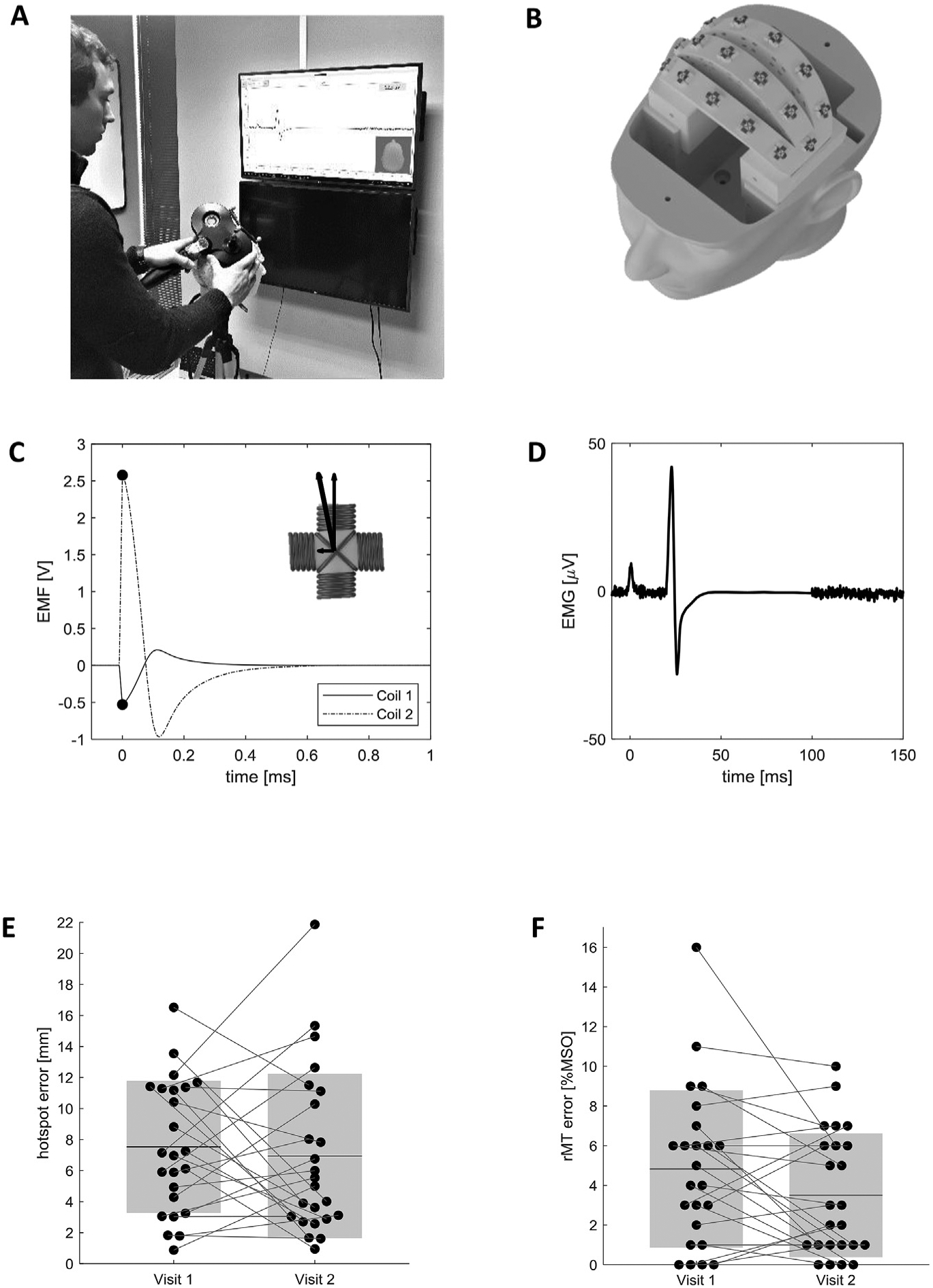
A) Study participant positioning the TMS coil on the phantom and monitoring the simulated EMG response. B) Internal layout of the phantom head, showing the 16 pairs of orthogonal sensing coils. Only one pair of sensing coils is active at any point in time, acting as a simulated hotspot. C) Electromotive force induced in the active sensing coil pair. The phantom detects the peak EMF in both coils and calculates the total EMF magnitude through vector summation. EMF magnitude is proportional to the TMS stimulator output, and to the proximity of the TMS coil to the hotspot. D) Visual feedback is provided to the operator by displaying a simulated EMG signal. The EMG peak-to-peak magnitude is proportional to the total EMF magnitude and to a configurable scaling factor. E) Measured hotspot localization error of all participants during the two visits. Black dots represent individual measurements, mean values are displayed as black horizontal lines, and the shaded areas represent ±1σ. F) Difference between the rMT values obtained by study participants and reference values recorded by an expert TMS operator. Black dots represent individual measurements, mean values are displayed as black horizontal lines, and the shaded areas represent ±1σ.
In the equation above, VEMG;p2p is the peak-to-peak amplitude of the simulated EMG signal, EMFpeak is the peak electromotive force, and VrMT is the minimum voltage threshold to reach a 50 μV EMG response. The phantom can be rapidly reconfigured via software, both by changing the hotspot location, and by scaling the minimum TMS output required to obtain a motor evoked potential (i.e. by changing the value of VrMT). We have chosen to change the rMT through the software, and have fixed coil locations, rather than having the coils move closer to or farther from the skull [4]. Additionally, a random component can be added to the EMG response to simulate the MEP variability observed in humans. We chose to reduce this variability to a range of ±1 μV to make the system more intuitive to complete novice users, but it can be increased to generate a more challenging scenario. Training and testing conditions can therefore be varied between sessions and individuals. ERIK can be programmed in one location, shipped to a remote location for testing, and then returned following the assessment. This may help in multisite clinical TMS trials.
To assess ERIK’s feasibility as a testing tool, we used him during two TMS training workshops at the Medical University of South Carolina. 24 TMS naïve workshop participants were asked to apply the techniques learned during the workshop to find the hotspot during two visits. The first at the beginning of the workshop after only a few lectures and little to no hands-on experience, and then again after two days following afternoon practice. They were trained in a systematic search method for finding the MH, which consisted in moving along a grid until they found the location with the largest MEP. Once they localized ERIK’s hotspot, they followed the MEP’s through the PEST algorithm [5] to determine the rMT [6]. All participants used the same Magstim 2002 stimulator with a D70 remote coil. Different phantom configurations (hotspot location and motor threshold) were randomly assigned to each participant and were kept constant between visits. Participants were blinded to ERIK’s configuration at both visits. For each visit, subjects drew the center position of the TMS coil on a cap placed on the phantom with landmarks identified for repositioning. We separately recorded the TMS machine output corresponding to the rMT, and qualitative comments regarding participants’ impressions. Participants did not receive any additional practice time on the phantom outside of the two testing visits, although it is ideally suited for that purpose as well. We evaluated its utility as an assessment tool rather than as a practice tool, although it can be both.
We measured the hotspot localization error by using a modified shell of the phantom with a notch above each pair of sensing coils. The cap used during testing was then placed on this modified shell, and we used a caliper to measure the distance between the TMS coil center marked by the participant and the reference notch. Motor threshold error was obtained by comparison with reference values recorded by an expert TMS operator. The expert operator was aware of the hotspot location and positioned the TMS coil center right above the sensing coil, which further reduced the potential for error.
During the first session, the average location error was 7.5 mm (σ = 4.3 mm), declining to 6.9 mm (σ = 5.3 mm) at the 2nd visit (Fig. 1E), (NS, paired 2-tailed t-test, p = 0.61). As shown in Fig. 1F, the visit 1 rMT had an average error of 4.8% MSO (σ = 4.0% MSO) and decreased as well to 3.5% MSO (σ = 3.1% MSO) for visit 2 (paired 2-tailed t-test, p = 0.058).
Overall, participants perceived the phantom as user friendly and intuitive. Several participants stated having a training tool that is transportable is an incentive for implementation into TMS protocols, and especially beneficial in multi-site studies. The primary recommendation was to coat the phantom with a soft layer to better mimic the interface between TMS coil and scalp (e.g. a layer of hair) and to reduce slippage of the coil.
In summary, we received positive feedback about ERIK as a training and testing tool. However, our comparisons between visits did not reach statistical significance, which may be due to the limited time between visits. The values of hotspot location error and rMT error were comparable, but slightly larger, to differences between expert and novice operators found by Zdunczyk et al. [7], indicating that the phantom provides a realistic simulation. Several participants appreciated the prospect of practicing on a machine rather than a human subject, as well as the immediate quantitative feedback. ERIK can be used to quantitatively assess participants’ proficiency with TMS, to track progress over time or to potentially test and certify TMS researchers and clinicians at remote labs. Reducing variance in the rMT, which then determines dose, can help reduce variance in clinical trials and therefore the sample size needed to test a hypothesis. ERIK may be used as a standardized teaching and testing tool that allows for repeatable training and testing conditions across participants and sites.
Acknowledgements
We would like to thank Dr. Steven Kautz for his continuous support throughout the project, and Philip Summers for his valuable input during the design of the phantom. A provisional patent titled “Transcranial Magnetic Stimulation Training and Testing Phantom” has been filed by the Foundation for Research Development of the Medical University of South Carolina (P1881; Finetto C, Kautz SA and George MS are listed as inventors).
Funding
Research reported in this publication was supported by funding from the National Institutes of Health National Center of Neuromodulation for Rehabilitation, NIH/NICHD grant number P2CHD0886844 which was awarded to the Medical University of South Carolina. The contents are solely the responsibility of the authors and do not necessarily represent the official views of the NIH or NICHD. This research was also supported by an Institutional Development Award (IDeA) from the National Institute of General Medical Sciences of the National Institutes of Health under grant number P20GM109040.
Footnotes
Conflicts of interest
None.
Contributor Information
Christian Finetto, Department of Health Sciences and Research, Medical University of South Carolina, Charleston, SC, USA.
Mark S. George, Departments of Psychiatry, Radiology and Neuroscience, Medical University of South Carolina, Charleston, SC, USA Ralph H. Johnson VA Medical Center, Charleston, SC, USA.
References
- [1].Rothwell JC, Hallett M, Berardelli A, Eisen A, Rossini P, Paulus W. Magnetic stimulation: motor evoked potentials. The international federation of clinical neuro-physiology. Electroencephalogr Clin Neurophysiol Suppl 1999;52:97–103. [PubMed] [Google Scholar]
- [2].Finetto C, Kautz SA, Summers P, Li X, George MS. Introducing ‘ERIK’, a TMS training and testing phantom. Brain Stimul 2018. Nov;11(6):e16. [Google Scholar]
- [3].Nieminen JO, Koponen LM, Ilmoniemi RJ. Experimental characterization of the electric field distribution induced by TMS devices. Brain Stimul 2015;8(3): 582–9. [DOI] [PubMed] [Google Scholar]
- [4].McConnell KA, Nahas Z, Shastri A, Lorberbaum JP, Kozel FA, Bohning DE, et al. The transcranial magnetic stimulation motor threshold depends on the distance from coil to underlying cortex: a replication in healthy adults comparing two methods of assessing the distance to cortex. Biol Psychiatry 2001. Mar 1;49(5):454–9. [DOI] [PubMed] [Google Scholar]
- [5].Awiszus F TMS and threshold hunting. Suppl Clin neurophysiol 2003;56: 13–23. [DOI] [PubMed] [Google Scholar]
- [6].Mishory A, Molnar C, Koola J, Li X, Kozel FA, Myrick H, et al. The maximum-likelihood strategy for determining transcranial magnetic stimulation motor threshold, using parameter estimation by sequential testing is faster than conventional methods with similar precision. J ECT 2004. Sep;20(3):160–5. [DOI] [PubMed] [Google Scholar]
- [7].Zdunczyk A, Fleischmann R, Schulz J, Vajkoczy P, Picht T. The reliability of topo-graphic measurements from navigated transcranial magnetic stimulation in healthy volunteers and tumor patients. Acta Neurochir (Wien) 2013. Jul;155(7):1309–17. [DOI] [PubMed] [Google Scholar]