Abstract
Longwall mining has a significant influence on gas wells located within longwall chain pillars. Subsurface subsidence and abutment pressure induced by longwall mining can cause excessive stresses and deformations in gas well casings. If the gas well casings are compromised or ruptured, natural gas could migrate into the mine workings, potentially causing a fire or explosion. By the current safety regulations, the gas wells in the chain pillars have to be either plugged or protected by adequate coal pillars. The current regulations for gas well pillar design are based on the 1957 Pennsylvania gas well pillar study. The study provided guidelines for gas well pillars by considering their support area and overburden depth as well as the location of the gas wells within the pillars. As the guidelines were developed for room-and pillar mining under shallow cover, they are no longer applicable to modern longwall coal mining, particularly, under deep cover. Gas well casing of failures have occurred even though the chain pillars for the gas wells met the requirements by the 1957 study. This study, conducted by the National Institute for Occupational Safety and Health (NIOSH), presents seven cases of conventional gas wells penetrating through longwall chain pillars in the Pittsburgh Coal Seam. The study results indicate that overburden depth and pillar size are not the only determining factors for gas well stability. The other important factors include subsurface ground movement, overburden geology, weak floor, as well as the type of the construction of gas wells. Numerical modeling was used to model abutment pressure, subsurface deformations, and the response of gas well casings. The study demonstrated that numerical models are able to predict with reasonable accuracy the subsurface deformations in the overburden above, within, and below the chain pillars, and the potential location and modes of gas well failures, thereby providing a more quantifiable approach to assess the stability of the gas wells in longwall chain pillars.
Keywords: Longwall mining, Gas well, Chain pillar, Casing stability
1. Introduction
In the eastern United States, abundant gas wells have been drilled through coal seams that are being actively mined by longwall mining. The existence of gas wells in the U.S. coal fields, whether active or abandoned, has caused many issues for longwall mining. First of all, any gas well in the mining area has to be located by all possible means. Secondly, the gas wells within longwall panels have to be plugged as cutting through gas wells will allow natural gas to flow into the active longwall mines. On the other hand, the gas wells within longwall chain pillars or barrier pillars can be left in place if the wells are protected by properly designed pillars.
Gas wells located within longwall chain pillars are influenced by longwall mining. Subsurface subsidence and abutment pressure can induce significant stresses and deformations in gas well casings. If the gas well casings are compromised or ruptured by excessive stresses and deformations, natural gas could migrate into the mine workings, potentially causing a fire or explosion. By the current safety regulations, the gas wells in the chain pillars have to be either plugged or protected by adequate coal pillars. The current regulations for gas wells in longwall chain pillars are based on the 1957 Pennsylvania Gas Well Pillar Study [1]. The study provided guidelines for gas well pillars by considering their support area, overburden depth, and the location of gas wells. Generally, for overburden depth greater than 198 m, the regulation requires a solid pillar area of 930 m2 with a minimum total bearing area of 3718 m2 or more. The regulation also stipulates to place the gas wells in the center of the pillars penetrated by the wells. As the guidelines were developed for room-and-pillar mining under shallow cover, they are no longer applicable to modern longwall mining, particularly under deep cover. Failure instances have occurred even though the chain pillars for the gas wells met the requirements of the 1957 study. However, without specific technical guidelines for gas well pillars under the influence of longwall mining, the 1957 study is still used to assess the gas well pillars in longwall mines.
Few studies have been conducted on gas well coal pillars. Peng et al. published the first gas well pillar study for longwall mining [13]. The paper presented two cases of gas wells in longwall chain pillars: one damaged and one successful. A three-dimensional finite element model was developed to analyze the stability of the gas wells in longwall chain pillars. The study concluded that the gas well was damaged by the excessive vertical deformation in the claystone layer in the floor under longwall-induced abutment pressure. The study also concluded that a weak rock layer existing in the roof or floor near the coal seam horizon is an important factor in potentially causing gas well failure.
More recent studies were conducted by Scovazzo et al. [2–7]. In 2012, in response to concerns surrounding unconventional gas wells, and upon recognizing that the 1957 study was formulated without data from modern day longwall mining, the Pennsylvania Department of Environmental Protection (PADEP) initiated a call for research to update the outdated regulation. In 2013 and 2014, a comprehensive gas well pillar study was conducted by a coal company and a few gas companies to collect data on subsurface deformations and the performance of gas well casings in longwall chain pillars. Four test wells within a longwall chain pillar were monitored and the results were published by Su et al. [2– 4,7]. These publications provide valuable data and analysis for understanding subsurface movements above chain pillars and the assessment of potential gas well failures in chain pillars. In 2016, the National Institute for Occupational Safety and Health (NIOSH) initiated a shale gas well stability project to quantify subsurface deformations above, within, and below longwall abutment pillars under different overburden depth and to provide critical scientific data for assessing the stability of shale gas wells drilled through coal seams. Some results of this research have been published by Su et al. [5,6].
The study described in this paper presented seven cases of conventional gas wells that were situated within chain pillars in the Pittsburgh Coal Seam. FLAC3D modeling was used to model the abutment pressure, subsurface deformations, and the performance of the gas well casings for one of the cases with gas well damage. The study demonstrated that numerical models are able to predict with reasonable accuracy the subsurface deformations in the overburden above, within, and below the chain pillars, and the potential location and modes of gas well failures, thereby providing a more quantifiable approach to assess the stability of the gas wells in longwall chain pillars.
2. Cases of gas wells located in chain pillars
Seven cases of gas wells located in longwall chain pillars have been collected in this study as shown in Table 1. All seven cases are from longwall panels in the Pittsburgh Coal Seam with overburden depths ranging from 153 to 308 m. The coal seam was about 1.9 m thick, and a claystone layer of about 0.24 m was present on the top of the coal seam. As the claystone was weak and susceptible to weathering, it was removed during development to make a mining height of about 2.1 m. The longwall panels were developed by a three-entry system with 4.9 m entries. Generally, the chain pillars were equally sized, but when gas wells were present in the chain pillars, the pillar sizes were adjusted so that the gas wells were placed in the larger pillars to meet the requirements of the gas well pillar regulation. The pillar stability factors based on the Analysis of Coal Pillar Stability (ACPS) under isolated loading were calculated for the seven cases, and the values ranged from 1.25 to 3.80 [8]. The distance from the wells to the edge of the gob varied from 12.8 to 25.9 m. Different numbers of casings were installed in each of the gas wells with a maximum of four casings at the coal seam horizon.
Table 1.
Cases of gas wells located in longwall chain pillars.
| Case # | Cover depth (m) | Gas well pillar |
Distance to the panel edge (m) | # of casings | Post-mining well condition | |||
|---|---|---|---|---|---|---|---|---|
| Width center (m) | Lenght center (m) | Total chain pillar width center (m) | Pillar stability factor | |||||
| 1 | 293 | 37 | 42 | 61 | 1.25 | 16 | 2 | Damaged 4.6 m below the coal seam. |
| 2 | 240 | 37 | 42 | 61 | 1.72 | 15 | 3 | Damaged 0.3 m below the coal seam. |
| 3 | 277 | 43 | 43 | 61 | 1.47 | 13 | 1 | Not damaged. |
| 4 | 308 | 49 | 37 | 67 | 1.32 | 26 | 4 | Not damaged. |
| 5 | 153 | 41 | 50 | 58 | 3.80 | 21 | 4 | Not damaged. |
| 6 | 159 | 36 | 66 | 61 | 3.80 | 15 | 2 | Not damaged. |
| 7 | 239 | 40 | 50 | 61 | 1.94 | 15 | 1 | Not damaged. |
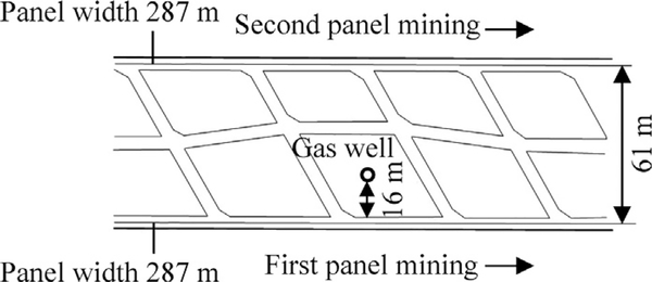
Of the seven cases, damage was found in two gas wells, and the other five wells were mined without safety issues. One gas well damage occurred 4.6 m below the coal seam after the second panel was mined as described by Luo et al., and another gas well damage occurred one foot below the coal seam also after the second panel was mined [9]. The gas well damages were in the form of plastic failure with the inner casings significantly deformed. This plastic failure was not associated with any fractures in the casings and did not interrupt gas production. Fig. 1 shows the chain pillar configuration for the gas well damaged 4.6 m below the coal seam. Two casings were installed in this well, and the annuli between the inner casing and the outer casing and between the outer casing and the surrounding rock were filled with cement. The other case with the well damaged at one foot below the coal seam had the same pillar configuration but had three casings installed.
Fig. 1.
Chain pillar configuration around the gas well damaged 4.6 m below the coal seam.
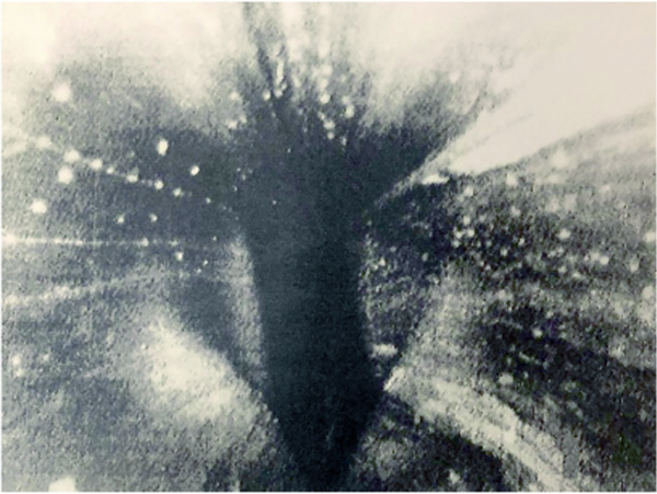
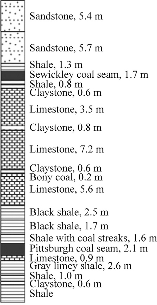
For the first damaged well case, the total gate-entry pillar width was 61 m center-to-center, with the gas well situated 16 m from the gob-side rib in the large 37 m center-to-center pillar. Fig. 2 shows the deformed gas well inner casing at a location approximately 4.6 m below the coal seam, as taken from a downhole camera. Fig. 3 shows the geological column of a corehole about 98 m north of the gas well. The overburden strata generally consisted of shale, sandy shale, claystone, sandstone, shaley limestone, and limestone. The immediate roof consisted of shale and limestone, and the immediate floor was limestone, shale, and claystone. A claystone layer of 0.5 m was present about 4.6 m below the coal seam. The information from the corehole constitutes the primary overburden geology input to the numerical model.
Fig. 2.
Deformed gas well inner casing 4.6 m below the coal seam.
Fig. 3.
Geological column 98 m north of the gas well.
3. Numerical modeling of gas wells in chain pillars
NIOSH researchers have developed a standardized procedure to model longwall-induced stresses and strata movements around the longwall panels using the FLAC3D modeling software [10–12]. The modeling procedures produce realistic results of stresses and deformations around the longwall pillars. The pillars, roof, floor, and overburden are modeled to achieve a full-scale, three–dimensional longwall model from the underground mining level to the surface. One advantage of the model is that it allows researchers to investigate not only the stress distributions but also the surface subsidence and strata deformations around the longwall panel.
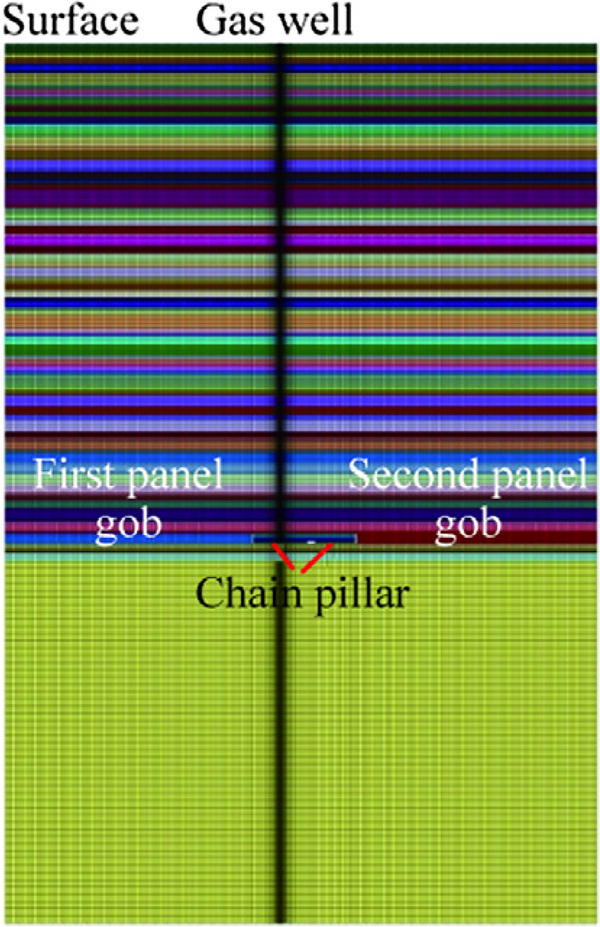
Using this procedure, a FLAC3D model was constructed for the gas well damaged 4.6 m below the coal seam based on the geological and mining conditions near the gas well. The model, which simulates a 3-m-thick slice across the width of the longwall panels, includes detailed inputs of the gas well installation and the sequence of the longwall retreating. Fig. 4 shows the sectional view of the model. The modeled overburden depth is 293 m. The full–scale model extends 223 m below the coal seam and 293 m above the coal seam up to the surface. The overburden strata is modeled by ubiquitous joint material, and the rock lithology in the overburden is obtained from the corehole 98 m north of the gas well. Bedding planes between rock types with large differential bending stiffness are modeled with interfaces. In addition, the MohrCoulomb failure criterion is used for the coal pillar, immediate roof, and floor. The gob is simulated by strain-hardening material implemented by the FISH scripting language available in FLAC3D. Horizontal stress is applied to the model by a horizontal-to-vertical stress ratio with a major horizontal-to-vertical stress ratio equal to three parallel to the panel and a minor horizontal-to-vertical stress ratio equal to two perpendiculars to the panel. The entire model consists of about 150,000 elements and 55 interfaces.
Fig. 4.
Sectional view of the FLAC3D model.
To model the effect of two longwall panels on the subsurface movements at the gas wells, the actual sequence of longwall mining and gas well installation are simulated. The gas well is installed before the first and the second panels are retreated.
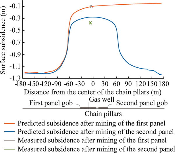
Fig. 5 shows the final surface subsidence profiles predicted by the numerical model after the first and the second panels are mined. The model predicts about 1.22 m of maximum subsidence around the center of the panels, about 7.62 cm of subsidence at the gas well location after the first panel is mined, and about 25.4 cm of subsidence at the gas well location after the second panel is mined. The measured subsidence at the gas well location was 7.62 cm after the first panel was mined and 35.6 cm after the second panel was mined. The predicted subsidence reasonably matches the measured subsidence at the gas well location. As the modeled 287-m-wide panel is subcritical for an overburden depth of 293 m, the predicted maximum subsidence is slightly less than the typical maximum subsidence of about 1.37 m for a supercritical panel with a 2.1-m mining height.
Fig. 5.
Surface subsidence predicted by the numerical model.
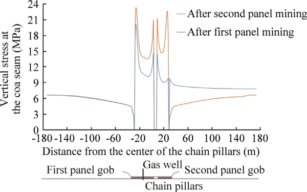
Fig. 6 shows the vertical stress distribution at the coal seam level across the chain pillars after the first and second panels are mined. It is important to note that the longwall-induced vertical stress at the gas well location at the coal seam level is predicted to be about 3.4 MPa after the first panel is mined and about 6.9 MPa after the second panel is mined. This vertical stress increase at the gas well has a direct influence on the amount of vertical stress that will be induced in the gas well casings.
Fig. 6.
Vertical stress distribution across the chain pillars at the coal seam level.
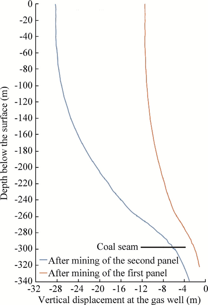
Fig. 7 shows the vertical displacement in the subsurface along the gas well after the first and second panels are mined. The maximum vertical displacement at the surface is about 11.4 cm after the first panel is mined and 28.4 cm after the second panel is mined. The vertical displacement along the gas wells in the subsurface gradually reduces down to about 7 cm at the coal seam level after the second panel is mined. Overall, the gas well is shortened by about 21.4 cm between the surface and the coal seam after both panels are mined.
Fig. 7.
Predicted vertical displacement at the gas well after the first and second panels are mined.
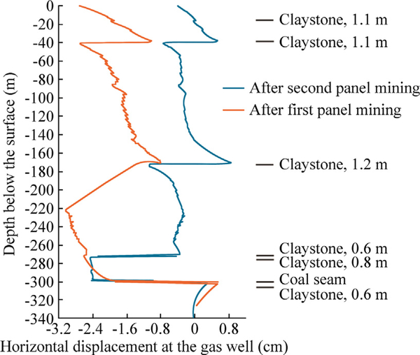
Fig. 8 shows the horizontal displacement in the subsurface along the gas wells after the first and second panels are extracted. The maximum horizontal displacement at the surface is 2.79 cm after the first panel is mined and 0.46 cm after the second panel is mined. The negative value means that the movement is towards the first panel. The ground moves towards the first panel when the first panel is mined, but moves back towards the second panel when the second panel is mined. It is important to note that the large horizontal displacements occur at weak claystone layers. After mining of the second panel, the horizontal displacement of about 2.5 cm is found at the claystone layers 4.6 m below the coal seam and also 18 m above the coal seam.
Fig. 8.
Predicted horizontal displacement at the gas well after the first and second panels are mined.
4. Effects of ground movements on the stability of gas well casings
Longwall-induced subsurface movements transfer deformations to the gas well casings through back-filled cement. As the modulus of steel is high, a small amount of subsurface movement will induce high stresses in the casings. In response to subsurface movements, the casings are likely to experience vertical compression or tension, horizontal compression, bending, and shear.
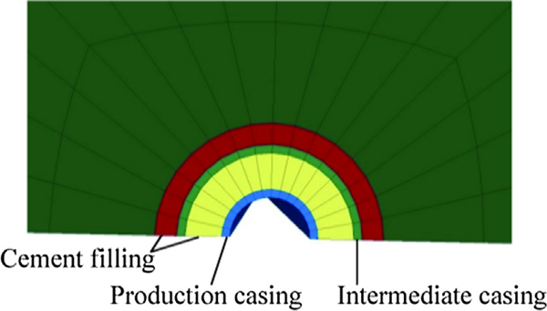
To evaluate the effects of ground movements on the stability of gas well casings, the construction of the casing and sequence of gas well installation have to be modeled. In this case, two casings are modeled as they were actually installed in the field. The annuli between the inner casing and the outer casing and between the outer casing and the surrounding rock are filled with cement fillings. Fig. 9 shows the casings constructed with cylinder shell mesh in the FLAC3D model. The steel casings are modeled with von Mises material, and the cement fillings are modelled with Drucker-Prager material.
Fig. 9.
Casings constructed in the model.
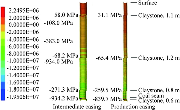
Vertical stress in the casings can be induced by differential vertical movement in the subsurface as well as by the weight of the casings. Fig. 10 shows the predicted vertical stress in the intermediate and production casings of the modeled gas well. The high vertical stress in the casings is found at weak claystone layers with low elastic modulus and high compressive strain. The highest vertical stress occurs at the claystone layer in the immediate floor. The tensile stress in the casing is also found in the upper portion of the casings. It should be noted that even though the casing is shortened from the coal seam to the surface as a result of abutment pressure, the upper portion of the casing can still experience tension due to a slight uplifting of the overburden near the surface over the chain pillars.
Fig. 10.
Vertical stress in the intermediate and production casings.
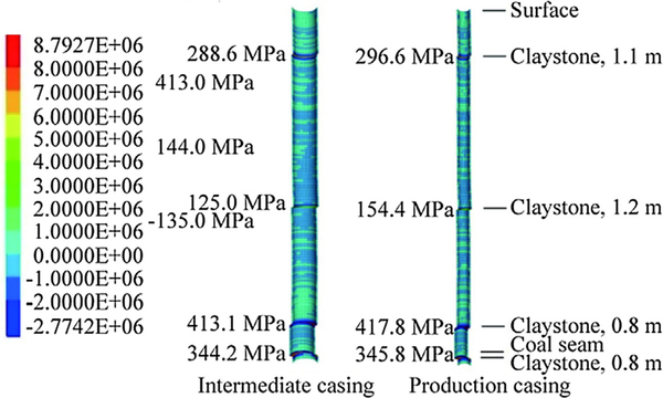
Differential horizontal movements along bedding planes in the subsurface induce shear stress in the casings. Fig. 11 shows the shear stress in the x-z plane in the intermediate and production casings of the modeled gas well. High shear stress occurs at the horizons with weak claystone layers. The maximum shear stress is found at the claystone layer in the immediate floor.
Fig. 11.
Shear stress in the intermediate and production casings.
Under the influence of subsurface movements and induced stresses in the casings, the stability of the steel casings can be assessed by the von Mises failure criterion. The von Mises equivalent stress can be calculated in FLAC3D using the following equation:
where σ1, σ2 and σ3 are the three principal stresses.
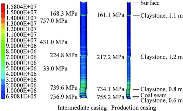
Fig. 12 shows the von Mises equivalent stress in the intermediate and production casings after both panels are mined. High von Mises stress occurs at weak claystone layers and also increases with the increase of depth. Based on the von Mises failure criterion, the casings will yield if the von Mises equivalent stress is greater than the yield strength of the steel. In this case, the peak von Mises stresses occur at the claystone layer in the immediate floor and in the roof 18 m above the coal seam and are above the yield strength of 276 MPa for typical conventional gas well casings. Therefore, the casings of the gas wells at those two claystone layers would be predicted to yield and induce plastic deformation. Typically, the claystone layers immediately below coal seams are generally weaker than those above coal seams, and thus, everything being equal, gas well damage would be more likely to occur in the immediate claystone floor, which occurred in this case.
Fig. 12.
Von Mises stress in the intermediate and production casings.
5. Stability of gas wells in longwall chain pillars
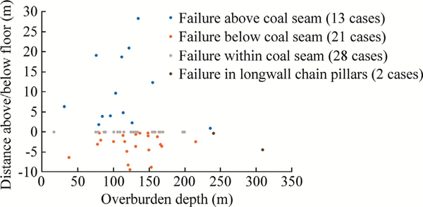
The stability of the gas wells in longwall chain pillars is influenced by the stability of the pillars themselves, as well as the location of the wells within the pillars, the stability of the floor, overburden geology, and the construction of the gas wells. To assess the stability of the gas wells in chain pillars, it is important to identify where gas well failures could occur in the overburden as well as within and below the coal seams. As gas well failures are very uncommon, the multiple failure cases from the PA 1957 gas well pillar study provide valuable data for the stability analyses of gas wells through coal seams [1]. Fig. 13 shows locations of gas well failures in the Pittsburgh Coal Seam as a result of retreat mining under different overburden depths. Of the 64 cases, 62 cases are from the 1957 study and two cases occurred in longwall chain pillars. Based on these failure cases, a gas well could fail in three horizons: in a coal seam, within 30 m of roof strata, and within 10 m of immediate floor. Fig. 13 indicates that as overburden depth increases, failures tend to occur nearer the coal seam horizon and mostly in the floor. It is important to note that all the failures in the roof strata occurred under shallower overburden depth less than about 152 m. These failures were likely to be associated with horizontal shear as a result of low friction along the interfaces of bedding planes and lower normal pressure on the bedding planes under shallow overburden depth.
Fig. 13.
Locations of gas well failures under different overburden depths.
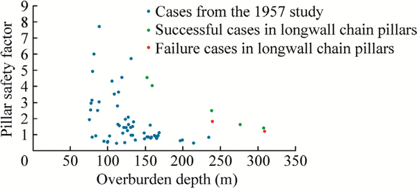
Stable pillars are a primary requirement for the protection of gas wells in chain pillars. If pillars fail, large deformations can be induced in gas well casings, likely resulting in the casing buckling. Fig. 14 shows the cases of gas well failures and their pillar stability factors under different overburden depths calculated by ACPS, which indicates that a vast majority of gas well failures occurred when the pillar stability factor was less than 2.0 [8]. Under deep cover, gas wells tend to fail in the pillars with smaller pillar stability factors. It should be noted that for overburden depths greater than 183 m, all the failure cases have a pillar stability of less than 2.0. Under shallow cover, the stability of the gas wells does not appear to be correlated with a pillar stability factor as many gas wells that failed have pillar stability factors greater than 2.0. These gas well failures in stable pillars help to confirm that the pillar stability factor is not the only determining factor for gas well stability.
Fig. 14.
Cases of gas well failures and their pillar stability factors under different overburden depths.
When pillars are stable, the location of the gas wells within the pillars has a great influence on the stability of the gas wells. If a well is close to the pillar rib, it could be in the yield zone of the pillar, potentially subject to large compressive strain in the casings. Furthermore, the distance of the wells from the edge of the gob determines how much abutment pressure is applied to the rock surrounding the wells, which subsequently affects the deformations and induced stresses in the gas well casings. It is not a good practice to place the wells within 6–15 m from the gob edge because the wells are very likely to be in a location near peak abutment pressure.
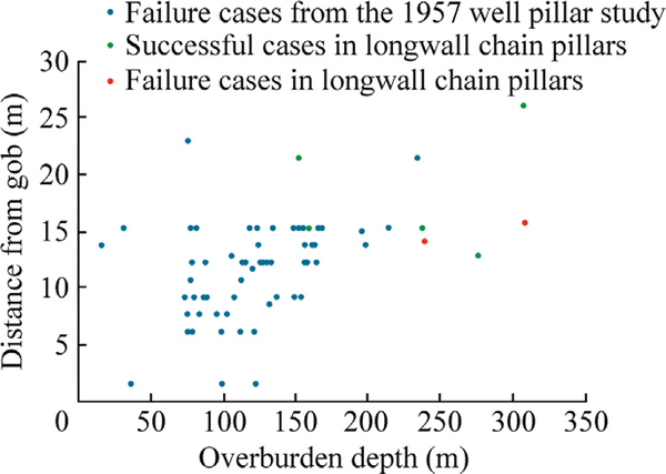
Fig. 15 shows failure cases of gas wells and the distance of the wells to the gob edge under different overburden depth. All of the failures occurred within about 24 m from the gob edge. A few failures occurred within 6 m of the gob edge, possibly within the pillar yield zone. Generally, if gas wells are more than 15 m away from the gob edge, they are away from both zones of pillar yield and peak abutment pressure; therefore, there is much less of a possibility of gas well failure as implied by Fig. 15. However, when pillars are stable and potential gas well failures are in the roof or in the floor, greater distance from the gas wells to the gob edge may be required to provide sufficient protection to the gas wells.
Fig. 15.
Failure cases of gas wells and the distance of the wells to the gob edge.
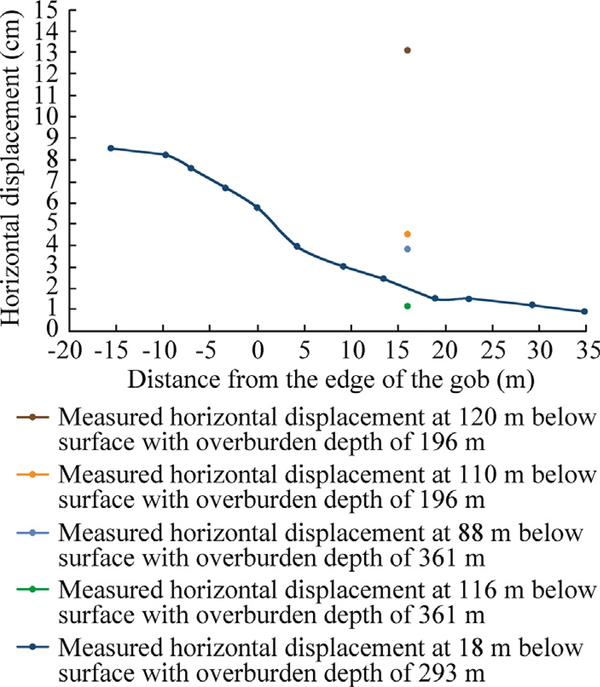
Gas well failures in the roof and overburden are largely associated with rock type and stratification, especially bedding planes between weak and massive, strong rock layers. Weak claystone layers and massive, strong sandstone/limestone layers have a major influence on horizontal displacement in the overburden over chain pillars. Large deformations can occur at weak claystone layers due to their low modulus and low friction along the interface with stronger, stiffer rocks. Fig. 16 shows the horizontal displacement along weak/strong interfaces in the overburden above a chain pillar. The blue-colored curve shows the modeled horizontal displacement at the claystone layer 18 m above the coal seam for the modeled case. The other data points are obtained from measurements of horizontal displacement over the chain pillars in two longwall mines in the Pittsburgh seam under shallow and deep cover [3,6]. All measured horizontal displacements occurred along the interfaces of weak claystone and strong sandstone/limestone layers. Large horizontal displacement up to 13.2 cm was measured in the overburden strata under an overburden depth of 184 m. The modeled horizontal displacement curve demonstrates that the influence zone of horizontal displacement can extend horizontally a large distance over a chain pillar even though the amount of displacement reduces rapidly away from the gob edge. The horizontal displacement over the chain is associated not only with conventional subsidence, but also with the effect of horizontal stress relief due to formation of the nearby longwall gob. Large horizontal displacements over chain pillars are more likely to occur at weak/strong interfaces in the overburden under shallow depth and could potentially induce high shear stress and shear failure in gas well casings.
Fig. 16.
Horizontal displacement in the overburden above a chain pillar.
Gas well failure in the floor is clearly associated with the presence of weak claystone in the floor, which is common in the Pittsburgh Coal Seam. In fact, some claystone layers in the Pittsburgh Coal Seam are very weak and sensitive to moisture. A claystone floor can induce not only vertical stress but also shear stress in gas well casings as shown in the modeled case. The induced vertical stress in the casings is associated with vertical compression of the weak rock layers, and the induced shear stress is related to horizontal shear displacement along the weak claystone layers in the floor. Gas well failure in the floor can occur under different overburden depths, depending on the amount of abutment pressure at the gas well and the strength and thickness of the floor as well as presence of water in the floor. As implied by the two damaged cases in the chain pillars, the gas well failure in the floor is a major concern under deep cover if claystone floor is present. Therefore, in evaluating the stability of the gas wells in chain pillars, floor stability should be assessed in addition to pillar stability and overburden horizontal movements.
Under the influence of abutment pressure and subsurface deformations, gas wells are likely to be subject to vertical compression, horizontal compression, and horizontal shear. The potential modes of failure for gas wells penetrating through coal seams are most likely to be buckling failure under vertical or horizontal pressure and shear failure along interfaces between weak and strong layers. The failure cases and numerical modeling of the damaged gas well demonstrate that, under deep cover, the location with the highest potential for failure is in the floor near the coal seam horizon. Past failure cases and field measurements of horizontal ground movements over chain pillars suggest that gas well shear failures could occur in the overburden above coal seams under shallow cover.
To assess the stability of the gas wells in chain pillars, it is important to quantify subsurface movements and their effect on gas well casings. This study shows that the standardized numerical modeling approach developed by NIOSH for longwall mining is an effective way to quantify subsurface deformations and induced stresses in gas well casings by taking into consideration geological and mining factors as well as the parameters of gas well construction. The sequence of longwall mining and gas well construction are important and should be incorporated into the numerical model. The stability of the gas wells can be evaluated by the numerically calculated von Mises stress in the casings.
6. Conclusions
Based on the analysis of gas well failure cases and numerical modeling of gas well stability in longwall chain pillars, the following conclusions are made:
The stability of gas wells in chain pillars are influenced by the pillar stability factor, overburden depth, gas well location, weak floor, overburden geology, and construction of gas wells.
Longwall mining induces subsurface movements including vertical, horizontal, and shear at gas wells located within chain pillars. These movements, in turn, induce vertical, horizontal, and shear stresses in gas well casings. Buckling and shear failure of casings may occur under excessive stresses and deformations.
For gas wells in chain pillars, potential failure could be buckling failure in the weak claystone floor under large overburden depth or shear failure along a weak claystone layer in the overburden above the coal seam under shallow overburden depth.
The standardized numerical modeling approach developed by NIOSH is an effective way to quantify subsurface deformations and induced stresses in gas well casings by taking into consideration the geological and mining factors as well as the parameters of gas well construction. Induced von Mises stress in gas well casings can be used to assess the stability of gas wells in chain pillars.
7. Disclaimer
The findings and conclusions in this report are those of the author(s) and do not necessarily represent the official position of the National Institute for Occupational Safety and Health, Centers for Disease Control and Prevention. Mention of any company or product does not constitute endorsement by NIOSH.
References
- [1].Commonwealth of Pennsylvania, Department of Mines and Mineral Industries, Oil and Gas Division. Joint Coal and Gas Committee, Gas Well Pillar Study; Harrisburg, Pennsylvania, 1957. p. 28. [Google Scholar]
- [2].Scovazzo VA, Moran RP, Moran.. Gas well pillar study update. PO 4300311202 and PO 4300400813: Pennsylvania Department of Environmental Protection, Bureau of Oil and Gas Management and John T. Boyd; 2016. p. 144. [Google Scholar]
- [3].Scovazzo VA. Mining effects on gas and oil wells pad NV-35 field experiment field monitoring. In: Proceedings of the 37nd International Conference on Ground Control in Mining Morgantown, WV: West Virginia University; 2018. p. 30–43. [Google Scholar]
- [4].Scovazzo VA, Moran RP. Industry research into gas and oil well protective coal pillar design. In: Proceedings of the 32nd International Conference on Ground Control in Mining Morgantown, WV: West Virginia University; 2012. p. 45–52. [Google Scholar]
- [5].Su DWH, Zhang P, Van Dyke M, Minoski T. Effects of cover depth on longwall-induced subsurface deformations and shale gas well casing stability. In: In Proceedings of the 52nd US Symposium on Rock Mechanics p. 19. [Google Scholar]
- [6].Su DWH, Zhang P, Van Dyke M, Minoski T. Effects of longwall-induced subsurface deformations on shale gas well casing stability under deep covers. In: Proceedings of the 37th International Conference on Ground Control in Mining Morgantown, WV: West Virginia University; 2018. p. 63–70. [Google Scholar]
- [7].Su DWH. Effects of longwall-induced stress and deformation on the stability and mechanical integrity of shale gas wells drilled through a longwall abutment pillar. In: Proceedings of the 35th International Conference on Ground Control in Mining Morgantown, West Virginia p. 119–25. [Google Scholar]
- [8].Mark C, Agioutantis Z. Analysis of coal pillar stability (ACPS): A new generation of pillar design software. In: Proceedings of the 37nd International Conference on Ground Control in Mining Morgantown, WV: West Virginia University; 2018. p. 1–6. [Google Scholar]
- [9].Luo Y, Peng SS, Zhang YQ. Analysis of the observed failure on the inner tubing of the gas well W-510 below the coal seam. Report for Cyprus Cumberland Resources Corp. College of Engineering and Mineral Resources, West Virginia University; 1999. [Google Scholar]
- [10].Esterhuizen GS, Mark C, Murphy MM. Numerical model calibration for simulating coal pillars, gob and overburden response. In: Proceedings of the 29th International Conference on Ground Control in Mining, Morgantown, 25–27 July 2010 p. 1–12. [Google Scholar]
- [11].Tulu IB, Esterhuizen GS, Mohamed KM, Klemetti TM. Verification of a calibrated longwall model with field measurements. Proceedings of the 51st US Rock Mechanics/Geomechanics Symposium, 25–28, June 2017 San Francisco, 2017. [Google Scholar]
- [12].ITASCA Consulting Group, Inc. 2017. FLAC-3D, Version 6.0, User’s Guide.
- [13].Peng SS, Morsy K, Zhang YQ, Luo Y, Heasley KA. Technique for assessing the effects of longwall mining on gas wells – two case studies. SME Trans 2003;314:107–15. [Google Scholar]


