

Abstract
The activity and selectivity of simple photocatalysts for CO2 reduction remain limited by the insufficient photophysics of the catalysts, as well as the low solubility and slow mass transport of gas molecules in/through aqueous solution. In this study, these limitations are overcome by constructing a triphasic photocatalytic system, in which polymeric carbon nitride (CN) is immobilized onto a hydrophobic substrate, and the photocatalytic reduction reaction occurs at a gas–liquid–solid (CO2–water–catalyst) triple interface. CN anchored onto the surface of a hydrophobic substrate exhibits an approximately 7.2‐fold enhancement in total CO2 conversion, with a rate of 415.50 μmol m−2 h−1 under simulated solar light irradiation. This value corresponds to an overall photosynthetic efficiency for full water–CO2 conversion of 0.33 %, which is very close to biological systems. A remarkable enhancement of direct C2 hydrocarbon production and a high CO2 conversion selectivity of 97.7 % are observed. Going from water oxidation to phosphate oxidation, the quantum yield is increased to 1.28 %.
Keywords: carbon nitride, CO2 reduction, interfaces, photocatalysis, solar fuels
Access all areas: A triphase interfacial CO2 reduction system over a carbon nitride photocatalyst enables the reactant CO2 to reach the reaction interface directly from the ambient atmosphere, which simultaneously enhances the reaction rate and suppresses the competitive hydrogen evolution.
Ever‐increasing consumption of fossil fuels along with the massive emission of carbon dioxide (CO2) has generated an energy crisis and resulted in climate change.1 Artificial photosynthesis through photocatalytic CO2 conversion into valuable chemicals (e.g., CO or H2, and, preferably, CH4, C2H4, etc.) in the presence of H2O has been recognized as a potentially promising way to resolve these issues.2 The transfer of photogenerated charge carriers and mass transport play crucial roles in determining the kinetics of catalysts and CO2 photoreduction efficiency.3 Meanwhile, the competitive reaction of photocatalytic hydrogen evolution also diminishes the generation of hydrocarbons, resulting in low selectivity and activity of CO2 reduction of most current systems. To overcome kinetic limitations and suppress the hydrogen evolution reaction, numerous efforts have focused on the improvement of pristine photocatalysts, by methods such as loading cocatalysts,4 tailoring morphologies,5 adjusting defect densities,6 and constructing heterojunctions.7 At the same time, the reaction interface that governs the solid–liquid contact and mass transfer is also of vital importance to the photocatalytic CO2 conversion process. Previous studies found that the availability of excess protons (H+) and low concentration of CO2 at the reaction interface lead to unsatisfactory activity and selectivity of the photocatalytic CO2 reduction system.8 In a conventional liquid–solid diphase system for CO2 photoreduction, the availability of CO2 at the reaction interface is dependent on its mass transfer through the water phase.9 The low concentration and slow diffusion rate of CO2 molecules in water thereby strongly hinder the surface catalytic process of CO2 photoreduction.
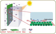
In this study, to overcome the limitations of the conventional liquid–solid diphase system of CO2 photoreduction, a simple and sustainable approach is developed by constructing a triphase (gas–liquid–solid) interfacial photocatalytic system. The photocatalysts are immobilized on the surface of a carbon fiber substrate (Figure 1). The concentration of CO2 molecules at the interface can be controlled by adjusting the surface adsorption on the substrate. Particularly, a hydrophobic substrate surface promotes CO2 localization from the gas phase and helps to rapidly deliver CO2 molecules to the contact area of gas (CO2), liquid (water), and solid (catalyst). Such a reaction system then allows the continuous delivery of CO2 molecules from the gas phase to the reaction interface via its hydrophobic channels, instead of the slow diffusion through the liquid phase. As a result, the accessibility of CO2 molecules to the photocatalyst is greatly increased, which subsequently enhances the rate of the reaction between CO2 and photogenerated electrons, thereby diminishing electron–hole recombination and increasing charge utilization. Finally, the activity and selectivity of photocatalytic CO2 conversion is remarkably improved.
Figure 1.
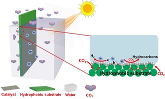
Schematic illustration of the triphase photocatalytic system with enlarged view of the solid–liquid–air triphase reaction interface (right).
As a proof of concept, we immobilized carbon nitride (CN) nanosheets onto the surface of a carbon fiber (CF) fleece with porous structure and different wettability. The contact angles (CAs) of the superhydrophilic, hydrophilic, and hydrophobic CF substrates are approximately 0°, 37.5°, and 112°, respectively (Figure 2 A–C). After CN immobilization on one side of the substrate, the side with the CN layer becomes superhydrophilic or hydrophilic with CAs of approximately 0°, 0° and 10° (see the Supporting Information, Figure S1; the corresponding samples are denoted as CN/CF1, CN/CF2, and CN/CF3, respectively). In this case, water can wet the hydrophilic photocatalyst layer while gas‐phase CO2 is directed through the hydrophobic substrate up to the CN particles, resulting in the formation of a gas–liquid–solid triphase boundary zone. Such a framework then secures the supply of both abundant water and CO2 molecules to drive overall CO2 photoreduction. Field‐emission scanning electron microscopy (FESEM) allows direct observation of the interface between immobilized CN photocatalysts and carbon fiber substrates (Figure 2 D, E).
Figure 2.
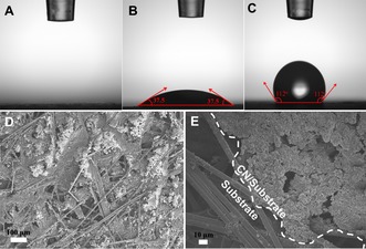
Contact angle measurement of water on (A) superhydrophilic CF, (B) hydrophilic CF, and (C) hydrophobic CF. FESEM images of CN coating on the surface of hydrophobic porous CF at (D) low and (E) high magnifications.
The powder X‐ray diffraction (XRD) patterns of CF, CN/CF1, CN/CF2, CN/CF3, and CN are shown in Figure 3 A. The pattern of CF exhibits a broad peak at around 26.5°, indexed as the (002) plane of a graphitic carbon structure, the fleece.10 Two distinct diffraction peaks appeared at 13.1° and 27.3°, corresponding to the (100) and (002) planes of CN, respectively. The former corresponds to the repeated structural packing of tri‐s‐triazine heterocycles in the conjugated planes, and the latter can be ascribed to the regular graphite‐like interlayer stacking.11 After the immobilization of CN onto the surface of the carbon fiber substrate, the XRD patterns of CN/CF show the characteristic peaks of both CN and CF. The peak intensity of CF in CN/CF samples gradually decreases from CN/CF1 to CN/CF3. This is due to the different surface energy of CF with varying surface wettability, resulting in different film thicknesses of the CN layer,12 although the primary loading of CN is identical. The optical absorption properties of all samples were then measured by UV/Vis diffuse reflectance spectroscopy (DRS; Figure 3 B). For CN, the absorption edge at 450 nm corresponds to its intrinsic band gap of 2.76 eV. CN/CF1, CN/CF2, and CN/CF3 show similar absorption edges but enhanced light‐absorption intensity in visible‐light regions, owing to the strong broad absorption of CF.13 Particularly, the absorption in this region of hydrophilic CF‐supported CN coated is stronger than that of hydrophobic CF‐supported CN, because of the different film thickness of photocatalyst layer, consistent with the XRD results. The different thicknesses of CN films affected the scattering of light among the texture and pore structure in CF substrates, which led to differences in the light absorption in the visible‐light region over CN/CF samples. FT‐IR spectroscopy was used to further investigate the surface structure of CN and CN/CF samples (Figure 3 C). The broad peaks between 3000 and 3500 cm−1 can be ascribed to the adsorbed hydroxy groups and the amino groups in CN, whereas the peaks at around 803, 1211, 1402, 1531, and 1639 cm−1 are the typical stretching vibrations of the s‐triazine ring system, C=N and C‐N heterocycles, respectively.14 All CN/CF samples show the same characteristic peaks as those of CN, suggesting that the coating of CN onto the surface of CF has no obvious effect on the structure of CN, and that CF only serves a platform for the immobilization of CN. In order to reveal the effect of surface wettability of CF on the charge separation efficiency for CN, photoluminescence (PL) spectra were measured (Figure 3 D). The intensity of all PL spectra is similar, indicating that the charge recombination rate in the samples of CN immobilized on CF with different surface wettability is similar. Namely, the expected performance difference of photocatalytic CO2 reduction could not be related to variation in the charge transfer dynamics within the series of catalysts.
Figure 3.
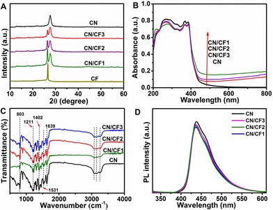
(A) XRD patterns, (B) UV/Vis DRS, (C) FTIR spectra, and (D) PL spectra of various samples.
The photocatalytic activity and selectivity of as‐prepared CN/CF photocatalysts were investigated under simulated sunlight irradiation in the absence of any sacrificial agent and co‐catalyst. The novel reaction environment of gas–liquid–solid (G–l–S) triphase reaction interface was employed (Figure S2). As a result, a spectrum of product molecules is found (Figure 4 A and Table S1); the main products of CO2 reduction are CH4, CO, C2H4 and H2 over CN/CF1, CN/CF2, and CN/CF3. On increasing the hydrophobicity of the CF substrate, the generation of hydrocarbon fuels from CO2 reduction reaction massively increases, whereas that of H2 from water splitting is suppressed. In particular, CN/CF3 shows the best performance with a total CO2 conversion of 415.50 μmol m−2 h−1, and a corresponding quantum yield of 0.33 %, which is higher than or comparable to reported results.15 This is of the order of natural photosynthesis, albeit here described with a much simpler synthetic system, free of further cocatalysts to increase the rate of hydrocarbon formation, as well as oxygen liberation. The CO2 conversion selectivity is as high as 97.7 %, as compared to that of H2 evolution. that is, 97.7 % of all electrons end up in carbon products. The rate of generation of C2 hydrocarbon product (C2H4), as well as that of CH4, over the hydrophobic substrate is significantly higher than that over the hydrophilic substrate. It can be concluded that CN immobilized onto the hydrophobic substrate experiences a continuous supply of CO2 molecules, thus making CO2 reduction processes much more effective than H2 generation under the given conditions of no metal cocatalyst. Moreover, increasing the loading amount of CN would further enhance the photocatalytic activity while maintain the high selectivity (see data of CN/CF4 in Table S1).
Figure 4.
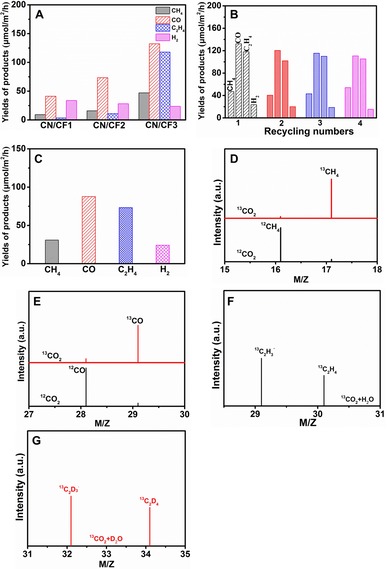
A) Photocatalytic activity of CN/CF1, CN/CF2, and CN/CF3 in the triphase system with CO2 atmosphere connection. B) Cycling test of photocatalytic CO2 reduction over CN/CF3 in the triphase system. C) Photocatalytic activity of CN/CF3 in the diphase system completely immersed in the water. D, E) GC‐MS analysis of reaction products CH4 (D) and CO (E) over CN/CF3 in the triphase system after irradiation for several hours with 12C and 13C as carbon sources. F, G) GC‐MS analysis of reaction products 13C2H4 (F) and 13C2D4 (G) over CN/CF3 in the triphase system after irradiation for several hours with 13CO2 as carbon source and D2O and H2O as hydrogen sources.
Furthermore, the good photocatalytic stability of CN/CF3 was demonstrated by a cycling test (Figure 4 B). The XRD pattern and contact angle of CN/CF3 were measured after the cycling test and showed no obvious change (Figure S3). To understand the unique interfacial effect, a controlled experiment was conducted in which the hydrophobic substrate immobilizing with CN (CN/CF3) was completely immersed in the water, which is similar with the conventional liquid–solid diphasic system (Figure S4). In this case, there was no direct contact between the substrate and CO2 atmosphere. Here, the necessary CO2 could only be supplied from the liquid phase. This test was conducted under the same reaction conditions as the triphase system. The main products of CO2 reduction in this liquid–solid diphase system are CH4, CO, C2H4 and H2, respectively. The total CO2 conversion reached 265.16 μmol m−2 h−1 (Figure 4 C). Indeed, by comparing the two experiments, we find the CO2 conversion rate in the triphase system to be twice that in the diphase system.
In addition, the production of O2 from water oxidation is the sole reaction to consume the photogenerated holes. Thus, we also monitored O2 evolution, which occurred at a rate of 711.95 μmol m−2 h−1 (Figure S5) by CO2 photoreduction over CN/CF3 in the triphase system, which is higher than the stoichiometric yield calculated from the given product distribution (644.34 μmol m−2 h−1). This deviation is reasonable within experimental error and might be related to undetectable species, such as methanol and ethanol, which end up dissolved in the water phase.
To confirm the carbon source of the photocatalytic products, isotope‐labeled CO2 was employed, and the hydrocarbon products carrying the isotopes 13C, 12C, and 2H (D) were detected by GC‐MS for the triphase system (Figure 4 D–G and Figure S6). The products labeled by 12C appear at earlier retention times than those labeled by 13C (Figure S6A). Clearly, the signals m/z=16.1 (12CH4) and m/z=17.1 (13CH4) were dominant in the GC‐MS spectra for photocatalytic 12C‐labeled CO2 and 13C‐labeled CO2 reduction, respectively (Figure 4 D). The signal at m/z=28.1 can be attributed to 12CO and 12C2H4, and that at m/z=29.1 can be attributed to 13CO when using 12CO2 and 13CO2, respectively (Figure 4 E). Subsequently, the isotope‐labeling experiments with carbon and hydrogen sources labeled with 13C and 2H (D) were performed for photocatalytic CO2 reduction over CN/CF3 (Figure S6B). The signals for molecular ethylene are at m/z=30.1 and m/z=34.1 when 13CO2 reacts with H2O and D2O, respectively. The signals at m/z=29.1 and m/z=32.1 are stronger those at m/z=30.1 and m/z=34.1, owing to the higher stability of the molecular ions (Figure 4 F, G).16 In conclusion, these results strongly indicate that the photocatalytic products originate solely from CO2 reduction.
In light of the above analysis, it is reasonable to propose a model to analyze the excellent CO2 photoreduction performance of CN/CF samples in the triphase reaction system (Figure 5 A, B). When the hydrophilic substrate was used to anchor the CN catalyst, a tiny proportion of CO2 molecules is supplied directly from the gas phase, and the majority is supplied from liquid phase to participate in photocatalytic CO2 reduction. Thus, the CO2 consumption and supply is unbalanced, resulting in a lower CO2 conversion rate. In contrast, when the hydrophobic substrate was used to anchor the CN catalyst, the main part of CO2 molecules is supplied directly from the gas phase with a high transport rate, thus a constant and higher interfacial CO2 concentration is maintained. As a result, the CO2 conversion rate and selectivity, as well as the amount of C2 molecules, are significantly higher over hydrophobic substrates than over hydrophilic substrates. To further demonstrate the significance of the continuous gas access, a diphasic system was analyzed as a reference, with the substrate immobilized with CN completely immersed in water (Figure 5 C). When the trapped CO2 molecules were isolated by the liquid phase, the diphase system disabled the continuous supply of CO2. Thus, the decreased concentration of interfacial CO2 resulted in lower conversion efficiency.
Figure 5.
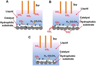
A, B) Behavior of photogenerated charge carriers and CO2 molecules for the hydrophilic substrate‐immobilized CN (A) and the hydrophobic substrate‐immobilized CN (B) in a triphase system. C) Schematic illustration of the CO2 molecule supply for the hydrophobic substrate‐immobilized CN that was completely immersed in the water.
There are still a number of means to improve the activity that were not explored in these first‐generation experiments. We still consider the rate‐determining step to be the four‐electron oxidation of water to dioxygen, which here proceeds in the absence of a cocatalyst. A kinetically much simpler reaction than O2 formation is the direct oxidation of phosphates to perphosphates.14a, 17 It was exciting to observe that CN/CF3 showed much higher activity when Na3PO4 was added to the water phase. In the triphase system, a CO2 conversion of 1413.85 μmol m−2 h−1 with a CO2 conversion selectivity of 95.5 % (Figure S7 and Table S2) and a quantum yield of 1.28 % were achieved. In this case, the synthetic photosynthesis even outperformed biological photosynthesis, in spite of its simplicity. Perphosphates therefore represent a valuable route of investigation, but also can be thermally or catalytically decomposed to liberate dioxygen to terminate product formation.17, 18
In summary, a triphase interfacial photocatalytic CO2 reduction system based on the gas–liquid–solid reaction interface allows efficient and continuous delivery of CO2 molecules to the catalyst surface and inhibits the hydrogen evolution reaction. The photogenerated charge carriers are efficiently utilized, resulting in significantly enhanced activity and selectivity in the photocatalytic CO2 reduction. In particular, the CN anchored onto the surface of a hydrophobic substrate (CN/CF3) exhibits about 7.2‐fold enhancement in the total CO2 conversion with 415.50 μmol m−2 h−1 as compared to the CN anchored onto the surface of superhydrophilic substrate (CN/CF1). This is accompanied by a CO2 conversion selectivity of 97.7 %, the remainder being the otherwise dominant H2 evolution. This product yield for photocatalytic CO2 reduction is also clearly superior to that with the conventional diphase system, and could be further enhanced by simplifying the photooxidation process from four‐electron dioxygen generation to perphosphate formation, with a CO2 conversion of 1413.85 μmol m−2 h−1 and a quantum yield of 1.28 %. Interestingly, a higher CO2‐based reactant flux also improved C2 hydrocarbon production, which reflects the higher chance of intermediate C1 species recombining at the catalyst surface. This work provides a platform to explore further interfacial architectures in system engineering of highly active semiconductor photocatalysts.
Conflict of interest
The authors declare no conflict of interest.
Supporting information
As a service to our authors and readers, this journal provides supporting information supplied by the authors. Such materials are peer reviewed and may be re‐organized for online delivery, but are not copy‐edited or typeset. Technical support issues arising from supporting information (other than missing files) should be addressed to the authors.
Supplementary
Acknowledgements
The authors acknowledge the financial support from the National Natural Science Foundation of China (21773179, 51922081, 51961135303, 51932007 and U1705251) and Max Planck Society, the National Key Research and Development Program of China (2018YFB1502001), the Natural Science Foundation of Hubei Province of China (2017CFA031).
Y. Xia, K. Xiao, B. Cheng, J. Yu, L. Jiang, M. Antonietti, S. Cao, ChemSusChem 2020, 13, 1730.
Contributor Information
Prof. Jiaguo Yu, Email: yujiaguo93@whut.edu.cn.
Prof. Shaowen Cao, Email: swcao@whut.edu.cn.
References
- 1.
- 1a. Li X., Yu J., Jaroniec M., Chen X., Chem. Rev. 2019, 119, 3962–4179; [DOI] [PubMed] [Google Scholar]
- 1b. Wang L., Wang L., Zhang J., Liu X., Wang H., Zhang W., Yang Q., Ma J., Dong X., Yoo S. J., Kim J.-G., Meng X., Xiao F., Angew. Chem. Int. Ed. 2018, 57, 6104–6108; [DOI] [PubMed] [Google Scholar]; Angew. Chem. 2018, 130, 6212–6216; [Google Scholar]
- 1c. Marszewski M., Cao S., Yu J., Jaroniec M., Mater. Horiz. 2015, 2, 261–278; [Google Scholar]
- 1d. Yu X., Yang Z., Qiu B., Guo S., Yang P., Yu B., Zhang H., Zhao Y., Yang X., Han B., Liu Z., Angew. Chem. Int. Ed. 2019, 58, 632–636; [DOI] [PubMed] [Google Scholar]; Angew. Chem. 2019, 131, 642–646; [Google Scholar]
- 1e. Zhao Y., Wang C., Liu Y., MacFarlane D. R., Wallace G. G., Adv. Energy Mater. 2018, 8, 1801400. [Google Scholar]
- 2.
- 2a. Zhong W., Sa R., Li L., He Y., Li L., Bi J., Zhuang Z., Yu Y., Zou Z., J. Am. Chem. Soc. 2019, 141, 7615–7621; [DOI] [PubMed] [Google Scholar]
- 2b. Cao S., Shen B., Tong T., Fu J., Yu J., Adv. Funct. Mater. 2018, 28, 1800136; [Google Scholar]
- 2c. Wu H., Li X., Tung C., Wu L., Adv. Mater. 2019, 31, 1900709; [DOI] [PubMed] [Google Scholar]
- 2d. Kuriki R., Yamamoto M., Higuchi K., Yamamoto Y., Akatsuka M., Lu D., Yagi S., Yoshida T., Ishitani O., Maeda K., Angew. Chem. Int. Ed. 2017, 56, 4867–4871; [DOI] [PubMed] [Google Scholar]; Angew. Chem. 2017, 129, 4945–4949; [Google Scholar]
- 2e. Yu L., Li G., Zhang X., Ba X., Shi G., Li Y., Wong P. K., Yu J. C., Yu Y., ACS Catal. 2016, 6, 6444–6454; [Google Scholar]
- 2f. Liu M., Wageh S., Ghamdi A., Xia P., Cheng B., Zhang L., Yu J., Chem. Commun. 2019, 55, 14023–14026. [DOI] [PubMed] [Google Scholar]
- 3.
- 3a. Singh A. K., Montoya J. H., Gregoire J. M., Persson K. A., Nat. Commun. 2019, 10, 443; [DOI] [PMC free article] [PubMed] [Google Scholar]
- 3b. Ou M., Tu W., Yin S., Xing W., Wu S., Wang H., Wan S., Zhong Q., Xu R., Angew. Chem. Int. Ed. 2018, 57, 13570–13574; [DOI] [PubMed] [Google Scholar]; Angew. Chem. 2018, 130, 13758–13762; [Google Scholar]
- 3c. Hu Z., Xiao X., Jin H., Li T., Chen M., Liang Z., Guo Z., Li J., Wan J., Huang L., Zhang Y., Feng G., Zhou J., Nat. Commun. 2017, 8, 15630. [DOI] [PMC free article] [PubMed] [Google Scholar]
- 4.
- 4a. Bie C., Zhu B., Xu F., Zhang L., Yu J., Adv. Mater. 2019, 31, 1902868; [DOI] [PubMed] [Google Scholar]
- 4b. Roy S., Reisner E., Angew. Chem. Int. Ed. 2019, 58, 12180–12184; [DOI] [PMC free article] [PubMed] [Google Scholar]; Angew. Chem. 2019, 131, 12308–12312. [Google Scholar]
- 5.
- 5a. Zhang G., Li G., Heil T., Zafeiratos S. S., Lai F., Savateev A., Antonietti M., Wang X., Angew. Chem. Int. Ed. 2019, 58, 3433–3437; [DOI] [PubMed] [Google Scholar]; Angew. Chem. 2019, 131, 3471–3475; [Google Scholar]
- 5b. Chao Y., Zhou P., Li N., Lai J., Yang Y., Zhang Y., Tang Y., Yang W., Du Y., Su D., Tan Y., Guo S., Adv. Mater. 2019, 31, 1807226; [DOI] [PubMed] [Google Scholar]
- 5c. Han E., Li Y., Wang Q., Huang W., Luo L., Hu W., Huang G., J. Mater. Sci. Technol. 2019, 35, 2288–2296. [Google Scholar]
- 6.
- 6a. Xia P., Antonietti M., Zhu B., Heil T., Yu J., Cao S., Adv. Funct. Mater. 2019, 29, 1900093; [Google Scholar]
- 6b. Jiao X., Chen Z., Li X., Sun Y., Gao S., Yan W., Wang C., Zhang Q., Lin Y., Luo Y. I., Xie Y., J. Am. Chem. Soc. 2017, 139, 7586–7594; [DOI] [PubMed] [Google Scholar]
- 6c. Sorcar S., wang Y., Grimes C. A., In S.-I., Mater. Today 2017, 20, 507–515. [Google Scholar]
- 7.
- 7a. Li H., Gao Y., Zhou Y., Fan F., Han Q., Xu Q., Wang X., Xiao M., Li C., Zou Z., Nano Lett. 2016, 16, 5547–5552; [DOI] [PubMed] [Google Scholar]
- 7b. Sorcar S., Thompson J., Hwang Y., Park Y., Majima T., Grimes C. A., Durrant J. R., In S.-I., Energy Environ. Sci. 2018, 11, 3183–3193. [Google Scholar]
- 8. Raciti D., Mao M., Park J. H., Wang C., Catal. Sci. Technol. 2018, 8, 2364–2369. [Google Scholar]
- 9.
- 9a. Liu Z., Sheng X., Wang D., Feng X., iScience 2019, 17, 67–73; [DOI] [PMC free article] [PubMed] [Google Scholar]
- 9b. Chen L., Sheng X., Wang D., Liu J., Sun R., Jiang L., Feng X., Adv. Funct. Mater. 2018, 28, 1801483; [Google Scholar]
- 9c. Wang D., Chen L., Ding Z., Feng X., Solar RRL 2019, 3, 1900185. [Google Scholar]
- 10.
- 10a. Hu Z., Huang J., Luo Y., Liu M., Li X., Yan M., Ye Z., Chen Z., Feng Z., Huang S., Electrochim. Acta 2019, 319, 293–301; [Google Scholar]
- 10b. Banerjee A., Bhatnagar S., Upadhyay K. K., Yadav P., Ogale S., ACS Appl. Mater. Interfaces 2014, 6, 18844–18852. [DOI] [PubMed] [Google Scholar]
- 11.
- 11a. Xu Q., Zhu B., Cheng B., Yu J., Zhou M., Ho W., Appl. Catal. B 2019, 255, 117770; [Google Scholar]
- 11b. Huang P., Huang J., Pantovich S. A., Carl A. D., Fenton T. G., Caputo C. A., Grimm R. L., Frenkel A. I., Li G., J. Am. Chem. Soc. 2018, 140, 16042–16047; [DOI] [PubMed] [Google Scholar]
- 11c. Wang J., Cao S., Yu J., Solar RRL 2020, 4, 1900469; [Google Scholar]
- 11d. Yu W., Xu D., Peng T., J. Mater. Chem. A 2015, 3, 19936–19947. [Google Scholar]
- 12.
- 12a. Li A., Cao Q., Zhou G., Schmidt B. V. K. J., Zhu W., Yuan X., Huo H., Gong J., Antonietti M., Angew. Chem. Int. Ed. 2019, 58, 14549–14555; [DOI] [PMC free article] [PubMed] [Google Scholar]; Angew. Chem. 2019, 131, 14691–14697; [Google Scholar]
- 12b. Sheng X., Liu Z., Zeng R., Chen L., Feng X., Jiang L., J. Am. Chem. Soc. 2017, 139, 12402–12405. [DOI] [PubMed] [Google Scholar]
- 13.
- 13a. Liu X., Chen C., Ye H., Jia Y., Wu Y., Jin A., Wang Y., Chen X., Carbon 2018, 131, 213–222; [Google Scholar]
- 13b. Liu X., Xu S., Chi H., Xu T., Guo Y., Yuan Y., Yang B., Chem. Eng. J. 2019, 359, 1352–1359. [Google Scholar]
- 14.
- 14a. Lin L., Ou H., Zhang Y., Wang X., ACS Catal. 2016, 6, 3921–3931; [Google Scholar]
- 14b. Wang K., Zhang G., Li J., Li Y., Wu X., ACS Appl. Mater. Interfaces 2017, 9, 43704–43715; [DOI] [PubMed] [Google Scholar]
- 14c. Fu J., Zhu B., Jiang C., Cheng B., You W., Yu J., Small 2017, 13, 1603938; [DOI] [PubMed] [Google Scholar]
- 14d. Han C., Li J., Ma Z., Xie H., Waterhouse G., Ye L., Zhang T., Sci. China Mater. 2018, 61, 1159–1166. [Google Scholar]
- 15.
- 15a. Ong W., Tan L., Chai S., Yong S., Mohanmed A., Nano Res. 2014, 7, 1528–1547; [Google Scholar]
- 15b. Liu L., Jiang Y., Zhao H., Chen J., Cheng J., Yang K., Li Y., ACS Catal. 2016, 6, 1097–1108; [Google Scholar]
- 15c. Yaghoubi H., Li Z., Chen Y., Ngo H. T., Bhethanabotla V. R., Joseph B., Ma S., Schlaf R., Takshi A., ACS Catal. 2015, 5, 327–335. [Google Scholar]
- 16. Xia Y., Tian Z., Heil T., Meng A., Cheng B., Cao S., Yu J., Antonietti M., Joule 2019, 3, 2792–2805. [Google Scholar]
- 17. Antonietti M., Savateev A., Chem. Rec. 2018, 18, 969–972. [DOI] [PubMed] [Google Scholar]
- 18. Zhang J., Grzelczak M., Hou Y., Maeda K., Domen K., Fu X., Antonietti M., Wang X., Chem. Sci. 2012, 3, 443–446. [Google Scholar]
Associated Data
This section collects any data citations, data availability statements, or supplementary materials included in this article.
Supplementary Materials
As a service to our authors and readers, this journal provides supporting information supplied by the authors. Such materials are peer reviewed and may be re‐organized for online delivery, but are not copy‐edited or typeset. Technical support issues arising from supporting information (other than missing files) should be addressed to the authors.
Supplementary