Abstract
A new approach has been developed to improve sensing performances of electrochemically grown Au nanostructures (AuNSs) based on the pre-seeding of the electrode. The pre-seeding modification is simply carried out by vacuum thermal deposition of 5 nm thin film of Au on the substrate followed by thermal annealing at 500 °C. The electrochemical growth of AuNSs on the pre-seeded substrates leads to impressive electrochemical responses of the electrode owing to the seeding modification. The dependence of the morphology and the electrochemical properties of the AuNSs on various deposition potentials and times have been investigated. For the positive potentials, the pre-seeding leads to the growth of porous and hole-possess networks of AuNSs on the surface. For the negative potentials, AuNSs with carved stone ball shapes are produced. The superior electrode was achieved from AuNSs developed at 0.1 V for 900 s with pre-seeding modification. The sensing properties of the superior electrode toward glucose detection show a high sensitivity of 184.9 µA mM−1 cm−2, with a remarkable detection limit of 0.32 µM and a wide range of linearity. The excellent selectivity and reproducibility of the sensors propose the current approach as a large-scale production route for non-enzymatic glucose detection.
Subject terms: Other nanotechnology, Materials for devices, Nanoscale materials
Introduction
During past decades, electrochemical sensing has attracted many attentions due to their considerable advantages such as high sensitivity, low cost, fast response time, wide linear range and portability and widespread applications1–9. Up to now various types of nanomaterial such as carbon nanotubes10, graphene11,12, noble metals13,14, metal oxides15, hybrid16 and composite nanostructures17,18 have been developed for electrochemical sensing. Among different nanomaterials, gold nanostructures (AuNSs) have attracted significant interests because of their remarkable electrical and catalytic properties, easy functionalization and excellent biocompatibility.
Since the electron transfer and catalytic activity of AuNSs strongly depend on their morphology and their size, extensive researches have been proposed in literatures to develop optimized AuNSs for sensing applications19,20. The notable approaches between them are based on the electrodeposition19, direct electrostatic self-assembly21, self-assembly with polymer22–24 and seed-mediated growth25–28. In the cases of self-assembly and seed-mediated strategies, the electron transfer and catalytic activity of AuNSs are hindered due to the existence of surfactant and linker molecules surrounding the nanostructures. The electrodeposition is the most reliable approach for shape and size controlled construction of AuNSs due to the possibility of controlling the nucleation and the growth processes. However, in this method the well control of morphology is provided by using template, surfactant or pre-treatment of the substrate that limit the applicability of the method20,29,30.
On the other hand, fabrication of nanoparticles by physical vapor deposition (PVD) provides a cost-effective and excellent reproducible method to produce nanoparticles directly on the substrate31,32. However, percolation of nanoparticles to form a thin film by increasing deposition thickness and limitation in shape diversity have restricted widespread application of PVD in biosensing33. Therefore direct construction of pure AuNSs with efficient substrate coverage without using templates, surfactant and stabilizer is a considerable challenge.
In the current work, a two-step approach is introduced to enhance the electrochemical performance of AuNSs deposited on an FTO substrate. In this regards, physical vapor deposition and annealing treatment have been utilized to modify an FTO substrate by seeding Au nanoparticles (AuNPs). The pure AuNSs have been deposited on the pre-seeded electrode by electrodeposition in very low concentrations of HAuCl4. The electrodeposition has been carried out at different potentials and times to investigate the effect of deposition parameters on the morphology and electrochemical properties of AuNSs. The results show that in addition to applying potential, pre-seeding of the substrate strongly influence the morphology and electrochemical properties of AuNSs. In addtition, the seeding modification leads to selective deposition and growth of AuNSs in the electrodeposition. Based on electrochemical results, the AuNSs deposited at 0.1 V for 900 s on the pre-seeded substrate has been selected as the optimum electrode for supplementary non-enzymatic detection of glucose. Due to biocompatibility of gold, the proposed Au-based electrodes in this work can be used for detection of many biomarkers in the forms of immunosensors and aptasensors. While the electrodes made by other transition metals in the non-enzymatic glucose detections cannot be used for various electrochemical immunosensing/aptasensing applications.
Results
Morphology characterization of AuNSs
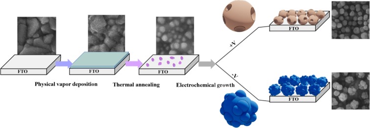
Fabrication procedure of AuNSs on the pre-seeded FTO is shown schematically in Fig. 1. To form seeding Au nanoparticles, a 5 nm Au thin film has been thermally deposited on FTO followed with the thermal annealing treatment at 500 °C. Figure S1 (in Supporting Information) shows the SEM images of the FTO substrate, the 5 nm Au thin film and the pre-seeded substrate, respectively. The Au thin film is physisorbed on the surface with a weak adhesion. By applying the annealing procedure, the Au nanoparticles are first formed on the surface and then these nanoparticles are gradually embedded in the glass of FTO because the annealing temperature is near the transition temperature of glass34,35. Such embedded Au nanoparticles in the glass are highly stable and act as seeding nanoparticles for the growth of AuNSs34,36,37.
Figure 1.
Schematic representation of the fabrication procedure of AuNSs by combining the physical vapor deposition, the thermal annealing, and the electrochemical growth on the FTO substrate.
After that, AuNSs have been electrodeposited on the pre-seeded substrate. By adjusting electrodeposition parameters, different sizes and various morphologies of the nanostructures can be produced19,38–40. Generally, the growth process of AuNSs are influenced by the deposition potential19,41, deposition time42,43, concentration and pH of HAuCl4 electrolyte19,43 and the surfactants used44–48. Here, an aqueous solution of HAuCl4 (0.5 mM) with pH of 3.2 without using any surfactant was used. The pH of the aqueous solution of 0.5 mM HAuCl4 was measured as 3.2. Therefore, the kinetics of the growth are controlled by the deposition potential and the deposition time. In order to study the effect of seeding modification, the AuNSs have electrochemically been deposited on the bare and the pre-seeded FTO substrates under the same conditions.
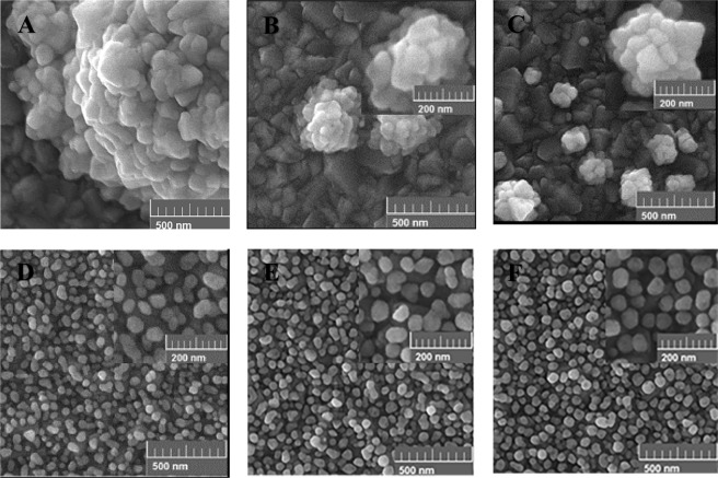
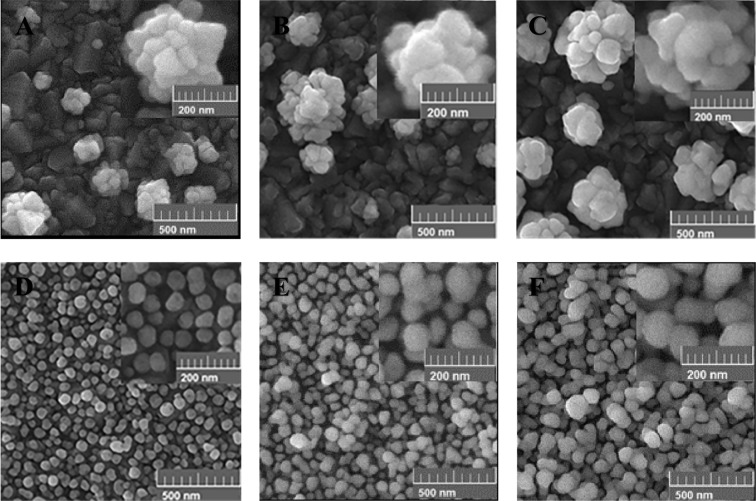
Generally, the morphology of AuNSs is strongly affected by the deposition potential. Different potentials in the range of −0.3 V to +0.5 V were applied. Figures 2 and 3 show the SEM images of the grown AuNSs on the bare and the pre-seeded FTO substrates at different positive (Fig. 2) and negative (Fig. 3) potentials, for time interval of 900 s. Comparing the images of the bare and the pre-seeded substrates at each deposition potential indicates considerable differences in the growth pattern, distribution, and coverage of the nanostructures. As shown in Fig. 2(A–C), for the bare FTO, sparse flower-like AuNSs are formed randomly. Also, the density of AuNSs increases gradually with the deposition potential from 0.5 V to 0.1 V, due to more nucleation on the surface. Figure 2(D–F) shows the growth behavior of AuNSs when the electrode is modified by the seeds of AuNPs. The pre-seeding of the substrate forms a dense array of semi-spherical AuNPs which is completely distinguishable from the bare electrode. By decreasing deposition potential from 0.5 V to 0.1 V, AuNPs become more roundish and uniform. In addition, at deposition potentials of 0.3 V and 0.1 V some tiny holes are observed on the AuNSs. The tiny holes are more observable for the lower potentials. It seems, in the case of the pre-seeded substrate, the AuNSs selectively grow on the seed AuNPs on the surface.
Figure 2.
Effect of the positive electrodeposition potential on the morphology of the AuNSs grown on the bare (A–C) and the pre-seeded FTO electrodes (D–F) for the deposition time of 900 s at different applying potentials of; (A,D) 0.5 V, (B,E) 0.3 V, and (C,F) 0.1 V.
Figure 3.
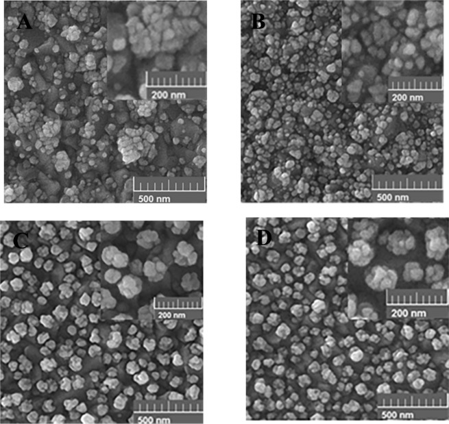
Effect of various negative potentials on the morphology of the AuNSs grown on the bare (A,B) and the pre-seeded FTO electrodes (C,D) for the 900 s time interval including: (A,C) -0.1 V and (B,D) −0.3 V.
The cause of formation of the holes on the AuNSs can be related to two factors of the crystallographic surfaces of the seeded Au-NPs49 and the growth mechanism in the electrodeposition process50. Different crystallographic surfaces of the seeded AuNPs may have different growth activities under the same electrochemical conditions. Therefore, the growth rate can be different for various crystallographic surfaces. On the other hand, the mechanism of growth depends on two kinetic factors including chemical diffusion of the gold ions and the subsequent reduction reactions on the electrode surface. Accordingly, by controlling the ratio of the reaction to the diffusion for the gold ions, different shapes of the AuNSs can be produced. In the case of positive deposition potentials, the low rate of the reactions on the surface leads to a reaction-limited growth process. In this case, the seeded AuNPs are surrounded by sufficient ions. Consequently, under the positive potentials, the AuNSs grow with spherical shape in addition to some holes on their surfaces.
Figure 3 shows the effect of various negative potentials on the morphology of AuNSs on the bare and the pre-seeded gold electrodes. The results show that the morphologies of AuNSs are considerably different for the bare and the pre-seeded electrodes under applying negative potentials. For the bare FTO substrate, in comparison to the positive potentials in Fig. 2, the flower-like shapes change to some irregular aggregated AuNPs shown in Fig. 3A,B. Moreover, with applying greater negative potentials, the density of AuNSs increases on the surface due to more fabricated nuclei of AuNPs. For the pre-seeded electrode (Fig. 3C,D), the Au morphology is similar to carved stone balls. Of course, no considerable difference is identified in the morphology of AuNSs with decreasing the potential from −0.1 V to −0.3 V. Similar to the positive potentials, the surface morphology of the pre-seeded electrode is clearly different from the bare one. In addition, the existence of almost regular growth of AuNSs on the pre-seeded substrate indicates the selective growth of AuNSs on the seeding AuNPs on the surface. In this case, the mechanism of the growth is mostly diffusion mode and a gradient of gold ions’ concentration is produced around the seeding AuNPs50.
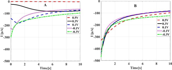
To have a better insight on the selective deposition and growth of AuNSs on the pre-seeded electrode, chronoamperometry technique was utilized. It is well known that the chronoamperometry technique gives details of the transient current38,41,51. Figure 4A shows the transient current-time (I-t) curve during the electrodeposition on the bare electrode. For more negative potentials, due to the fast formation of the nucleus on the surface of the electrode, higher currents are observed in the earliest times of the characterizations. We see that for the potential 0.5 V, a tiny current less than 100 µA is measured. For the deposition potentials of 0.3 V and 0.1 V, the current is below 200 µA. However, for the potentials of −0.1 and −0.3 V, the maximum current is between 200–300 µA. In the Fig. 4B, we see that with seeding modification of the surface, the initial currents of the samples are considerably greater than the similar cases without pre-seeding. The initial current for all voltages are more than 300 µA, which is even greater than the peak current between the samples without pre-seeding. The time evolution of the current in the pre-seeded samples can be described by the inverse square root of the time which is known as the Cottrell equation51.
| 1 |
where, I(t) is the current, n is the number of electrons involving in the reduction reaction, F is the Faraday constant, A is the surface area, D is the diffusion coefficient and C0 is the initial concentration of electroactive species. With changing the electrodeposition potential, the density of electrons involved in the deposition changes and therefore we see different inverse-square curves for different potentials.
Figure 4.
Chronoamperometry curves of electrodeposition of gold on the bare (A) and the pre-seeded FTO electrode (B), for different deposition potentials.
A distinct difference between the curves of the pre-seeded and the bare samples is the lack of the negative peak of the current in the pre-seeded sample as shown in Fig. S2. Such peak generally relates to nucleation of tiny AuNPs on the bare samples38,51,52. This causes that the current increases in the early stages of the deposition for the bare sample. However for later times, the covering of the surface by the AuNSs leads to decrement of the current and convolution of these two phenomena leads to a negative peak in the current for the bare surfaces. However, for the pre-seeded substrate, the nucleation process cannot take place due to the existence of the seeding AuNPs and consequently the only covering stage, which is proportional to the inverse square root of the time, is seen for the current. In the pre-seeded samples, the electrodeposition of gold mainly occurs onto the seeded Au places rather than on the defect places of the substrate53,54.
The deposition time is another parameter affecting the morphology and the electrochemical properties of the fabricated AuNSs. Figure 5 shows the morphological evolution of AuNSs deposited at 0.1 V on the bare and the pre-seed electrodes with different deposition times. The selection of the potential of 0.1 V, is based on the best current response of this potential between all examined positive and negative deposition potentials. In the case of the bare electrode (Fig. 5A–C), as the deposition time increases from 900 s to 3600 s, the size of flower-like AuNSs increases due to the formation of more branches on the existing nuclei, without noticeable increment in the density of the nanostructures. For the pre-seeded electrodes (Fig. 5D–F), longer deposition times of 1800 s and 3600 s lead to formation of a porous network of nanostructures, which gradually cover all of the substrate. It should be mentioned that the observed holes on the AuNSs at 900 s disappear for longer deposition times of 1800 s and 3600 s.
Figure 5.
Effect of the deposition time on the morphology of the AuNSs grown on the bare (A–C) and the pre-seeded FTO electrodes (D–F) at 0.1 V for different deposition times of 900 s (A,D), 1800 s (B,E) and 3600 s (C,F).
The further characterizations of various samples have been carried out by XRD and AFM and the results have been shown in the supporting information (Figs. S3 and S4). These characterizations clearly support the formation of pre-seeding AuNPs on the FTO substrate and subsequent growth of AuNSs by the electrodeposition.
Electrochemical performance of the AuNSs
In order to study the electrochemical behaviors of different electrodes before growth of AuNSs, the cyclic voltammetry (CV) and electrochemical impedance spectroscopy (EIS) measurements have been carried out for the three electrodes of the bare FTO (BFTO), 5 nm Au on FTO and the the pre-seeded FTO (SFTO) and the results are shown in Fig. S5. The CV curves have been obtained at the potential window of 0–0.6 V in the solution KCl (0.1 M) containing redox couple of [Fe (CN)6]3-/4- (2.5 mM), at the scan rate of 50 mV s−1. In addition, the EIS results at the frequency range of 1 MHz to 0.1 Hz were acquired.
The cyclic voltammograms of the three electrodes are shown in Fig. S5A. It is seen that after the modification of the BFTO by the ultrathin Au film, a pair of redox peaks appear in the cyclic curves, which is accompanied with a remarkable increase in both anodic and cathodic peaks. It is also seen that the voltage difference between the oxidation and reduction peaks (identified as ΔEP) decreases with the Au modification of the surface. Thermal processing of the 5 nm Au film leads to more increasing in the intensity of current peaks in addition to more decreasing ΔEP. Therefore, an improved sensing behavior from the modified electrode is expected based on the shown electrochemical characterizations.
In addition to the CV study mentioned here, EIS analysis can provide further information since the diameter in the Nyquist plots equals the electron-transfer resistance (described as Ret). Figure S5B shows the Nyquist plots of the BFTO, 5 nm Au/FTO and the SFTO. For the BFTO, a large Ret is observed indicating a great resistance against charge transfer at the bare electrode surface. After deposition of the ultrathin Au film, a notable decrease in Ret occurs. A further decrease in Ret is observed after thermal treatment of the ultrathin Au film, which mostly relates to increment of active surface area of the electrode due to formation of seeds of AuNPs.
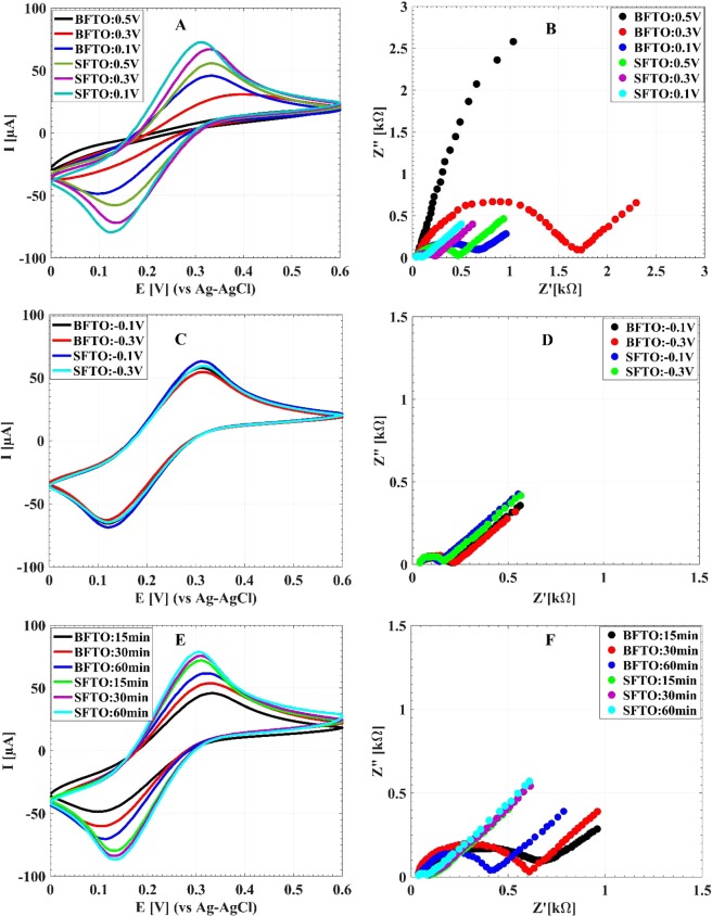
The electrochemical performances of the electrodeposited AuNSs on the SFTO in comparison with those of the BFTO for different deposition potentials and times are shown in Fig. 6. The CV and EIS curves for different positive potentials with fixed deposition time of 900 s are shown in Fig. 6A,B, respectively. With decreasing the potential from 0.5 V to 0.1 V, the value of peak current iP increases along with decreasing of the value of ΔEP for both the BFTO and the SFTO substrates. Also at each applying potential, a noticeable increment in iP and a decrement in EP are seen for the SFTO relative to the BFTO one. From the EIS results, it is seen that with decreasing the deposition potential from 0.5 V to 0.1 V, a considerable decrease in Ret value is observed for both the pre-seeded and the bare electrodes (Fig. 6B). It is noticeable that an extreme reduction of Ret for the SFTO electrodes relative to the BFTO ones is observed for all positive electrodeposition potentials. Therefore, for the positive potentials, seeding modification results in significant boosting of the electrochemical performance of the electrodes after the electrodeposition of AuNSs.
Figure 6.
The CV and EIS responses of the BFTO and the SFTO after electrodeposition of AuNSs. Graphes A and B display the CV and EIS responses of AuNSs grown during 900 s with different positive deposition potentials. Graphes C and D display the CV and EIS results for the 900 s growth of AuNSs with various negative deposition potentials. Graphes E and F display the CV and EIS results for the optimum deposition voltage of 0.1 V with various deposition times.
On the contrary to the positive potentials, there is no noticeable difference between the electrochemical performances of AuNSs deposited on the SFTO and the BFTO electrodes for negative applying potentials, as shown in Fig. 6C,D. Although in this case, the performance of the SFTO is still better. The lack of a significant difference between the two electrodes for the negative potentials may be related to their surface morphologies and the similarly of their surface coverage (see Fig. 3). Comparing the results obtained for the negative and the positive potentials demonstrates that the AuNSs deposited on the SFTO at 0.1 V has the best electrochemical performance in all examined deposition potentials.
The effect of deposition time on electrochemical characteristics of AuNSs for the applied potential of 0.1 V, is shown in Fig. 6(E,F). By increasing the deposition time from 15 min to 60 min, no significant changes in electrochemical performance of AuNSs for the SFTO is observed. While, for the BFTO, the electrochemical performance improves with the deposition time. It is noticeable that the AuNSs deposited on the SFTO for 900 s has a better electrochemical performance in comparison to the 3600 s deposition on the BFTO. Also comparing the results of Figs. S5 and 6E,F reveals that the SFTO with no AuNSs deposition has better electrochemical performances than the BFTO even with AuNSs deposited on it at 0.1 V during 30 min. Based on the results of Fig. 6, the AuNSs on SFTO at 0.1 V for 15 min is the superior electrode for supplementary sensing experiments in this work.
The difference in the iP values of AuNSs deposited on the SFTO compared to the BFTO suggests an improvement of electroactive surface area (ESA) of the AuNSs. The ESA is calculated using the well-known equation of Randles–Sevcik equation55:
| 2 |
with Ip the peak current (A), n the number of electrons transferred in the reaction, A the electroactive surface area (cm2), D the diffusion coefficient (cm2 s−1), C0 the initial bulk concentration of electroactive species (mol cm−3), and v the scan rate (Vs−1). Figure S6 represents the CV curves of AuNSs deposited on the SFTO and SFTO at 0.1 V for 900 s at different scan rates. Based on the slope of Ip versus v1/2 with linear regression equation, the ESA of the AuNSs deposited on the SFTO and the BFTO are obtained as 0.074 and 0.147 cm2, respectively. These results indicate significant boosting of the accessible surface area by the seeding modification of the substrate.
Electrooxidation of glucose
The electrocatalytic activity of the superior electrode toward glucose oxidation was investigated by measuring CV curves in absence and presence of 1 mM glucose in NaOH electrolyte (0.1 M) at the scan rate of 20 mV s−1, as shown in Fig. 7. In the absence of glucose, the CV curve shows three substantial peaks. In the forward scan, the anodic peak at 0.33 V correspondes to the oxidation of gold. In the backward scan, the first cathodic peak relates to the reduction of gold oxides at 0.15 V and second cathodic peak corresponds to desorption of hydroxide layer at −0.13 V. After the addition of 1 mM glucose to the electrolyte, several CV peaks associating to the glucose oxidization appear. During the positive potential scan, a rise in the anodic current is observed at the onset potential of −0.80 V in addition to the three main anodic peaks at −0.45 V (A), −0.06 V (B) and 0.21 V (C). The first peak (A) imputes to the partial oxidation of glucose. The peak at −0.06 V (B) corresponds to subsequent oxidation of the gluconolactone56. At more positive potentials, the density of AuOH sites increases on the substrate surface, which catalyzes oxidation of gluconolactone, and provides new active sites for the direct oxidation of glucose leading to the peak at 0.21 V (C). The decrease in the current after the third peak is induced due to the oxidation of gold surfaces, leading to the decline in the density of AuOH sites and inhibiting the oxidation of glucose. In the backward scan, due to the reduction of the gold oxide, sufficient active sites will be accessible for the direct oxidation of glucose, making an cathodic peak at 0.13 V (D). Along with the potential moving to more negative values, the partial oxidation of glucose at the sites of AuNSs occurs again that results in the rise of the gluconolactone quantity on the surface and consequently increasing the current in the potential range of −0.16 V to −0.4 V57.
Figure 7.
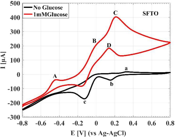
Current versus potential profiles of the superior electrode in the absence and presence of 1 mM glucose in NaOH solution (0.1 M). Scan rate: 20 mV s−1.
A comparison between the electrocatalytic activity of AuNSs deposited on the SFTO with the BFTO is shown in Fig. S7. In the absence of glucose (Fig. S7A), the CV current peaks of the AuNSs on the SFTO are considerably higher than the BFTO indicating high surface activity of the seed modified electrode. After the addition of 1 mM glucose, as shown in the Fig. S7B, the BFTO displays a peak of partial oxidation of glucose at about −0.28 V whereas the partial oxidation peak of the SFTO occurs at considerably lower anodic potential at −0.45 V. At more positive potentials, the seed modified electrode shows higher rates of reaction in comparison with the bare one so that at the direct oxidation potential of 0.21 V, the maximum current is 3.3-fold higher than that of the BFTO. It can be seen, in backward scan that the seed modified electrode exhibits higher rates of reaction than that of the bare one. The remarkable decrease in the partial oxidation potential, the higher reaction rates and the 3.3-fold higher current for AuNSs on the SFTO in comparison with the BFTO demonstrate the significant improvement of glucose electrooxidation occurring by the seeding modification.
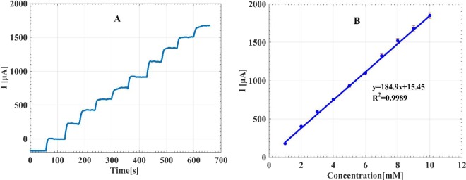
For the electrochemical sensing applications, amperometric detection is usually employed. For amperometric detection, it is essential to find a proper detection potential to achieve the highest sensitivity and selectivity responses. As mentioned above, all corresponding peak potentials can be utilized to investigate the catalytic activity of the electrode. Since the detection at lower potentials such as −0.45 V eliminates easily oxidizable species such as ascorbic acid (AA) and uric acid (UA), we selected the potential of −0.45 V for the amperometric detection of glucose56,58. Figure 8 shows the amperometric response and the calibration curve of the AuNSs on the SFTO at the constant potential of −0.45 V for successive additions of 1 mM glucose in the NaOH electrolyte (0.1 M). From the calibration curve, a linear range to the glucose detection is obtained in the concentration range from 1–10 mM with a sensitivity of 184.9 µA mM−1 cm−2, achieved from the slope in the linear range. The performance of this sensor is compared to some of the other published non-enzymatic sensors based on AuNSs embeded on the surface, as listed in Table S1. Based on the desirable sensitivity, limit of detection, and linear response range that a typical non-enzymatic glucose sensor should have, the sensor of the current work can fulfill all required specifications for the practical applications. The remarkable properties of the current sensor is related to high surface area and excellent electrical conductivity of the electrode, which leads to fast and direct electron transfer during the electrooxidation of glucose.
Figure 8.
(A) The amperometric responses of the AuNSs to the successive addition of glucose with the concentrations from 1 mM to 10 mM in NaOH solution (0.1 M) at the constant potential of −0.45 V. (B) The corresponding calibration curve of the sensor for various glucose consentrations.
The selectivity of the sensor was studeied in presence of common interference species such as UA, and AA in addition to other sugars including lactose, sucrose, mannose, and fructose, in physiological levels59,60. Addition of 0.02 mM UA, 0.1 mM AA, and also other sugars to a 1 mM glucose solution lead to only 0.2–4% increase in the current and does not interfere with the glucose detection, as shown in Fig. S8A. In addition, the selectivity of the sensor in the presence of 0.1 M NaCl, 0.1 M MgCl2, 0.01 mM tyrosine (Tyr), 0.03 mM phenylalanine (Phe) and 0.1 mM glutamine (Gln) is shown in Fig. S8B.
The operational stability was studied by measuring the CV curves for several cycles. The current response of the electrode to 20 cycles in the presence of 1 mM glucose is displayed in Fig. S8C. It is seen that from the third cycle to the next ones, the current response remains stable during the electrochemical measurements. The storage stability is also examined by amperometric determination of glucose at −0.45 V for periods of 5 days. The results show only 5% decrease in current response respect to its initial response after one-month (Fig. S8D), which indicates that the electrode is stable and can be suitably used in all practical measurements of glucose.
The practical utility of the sensor was studied by glucose measuring for 3 human serum samples, and the results were compared with the reference values obtained from clinical measurements in Shariati hospital of Tehran (Iran). As shown in Table S2, it is seen that the obtained results from sensor exhibit an excellent agreement with the clinical measurements with less than 3.2% deviation. This indicates that the proposed sensor of this work can well be employed for practical testing with beneficial accuracy. Also, the recovered test has been performed for the sensor, and the results have been shown in Table S2 too. The selected serum samples were injected with known glucose concentrations of 0.5 mM. It was found that the recovery range is between 98–103% for the examined human serums. In addition, the relative standard deviation (RSD) of the glucose measurements of the human samples were found between 2.37–3.2.
Conclusion
In this work a seeding modification approach has been applied to enhance electrochemical performance of AuNSs. A template-less and surfactant free electrodeposition method has been used to direct growth of AuNSs on the BFTO and SFTO. The electrochemical measurements reveal noticeable enhancement of the active surface area and charge transfer performance of AuNSs due to the pre-seeding of the substrates. The influences of electrodeposition potential and time on the morphology and electrochemical properties of the fabricated AuNSs have been investigated. Based on the electrochemical results, the AuNSs deposited at 0.1 V for 900 s on the SFTO was selected as the superior electrode for glucose detection. The results show excellent electrocatalytic activity of this electrode toward glucose oxidation with presenting a high sensitivity of 184.9 µA mM−1 cm−2 and a low limit of detection of 0.32 µM.The electrode presents remarkable anti-interference characteristics, operational and storage stabilities.
Methods
Materials and chemicals
Au metallic pellets were purchased from Kurt J. Lesker. Fluorine-doped tin oxide (FTO) substrates obtained from Sharifsolar company, with a thickness of 3.3 mm and surface resistance of 20 Ωsq−1. Chloroauric acid (HAuCl4), potassium ferricyanide [K3Fe (CN)6], potassium ferrocyanide [K4Fe (CN)6], Glucose, NaOH, and other reagents were bought from Merck Company. All chemical materials were of analytical grade and used without further purification. All solutions were prepared with Milli-Q water (18.2 MΏcm).
Apparatus
Typical electrochemical measurements and depositions were carried out with an Origalys (ElectroChem SAS, France) potentiostat/galvanostat system. The conventional three-electrode cell comprising a modified working electrode, a platinum foil auxiliary electrode, and an Ag-AgCl reference electrode, was used for all electrochemical experiments. The surface morphology of the fabricated electrodes was characterized with field emission scanning electron microscopy (FESEM), FEI Nova NanoSEM 450 model. The surface topographies of the fabricated electrodes were acquired by atom force microscopy (AFM, Nanosurf Flex, Swiss). X-ray diffraction (XRD) pattern were collected on the X’Pert PRO MPD system equipped with Cu-Kα radiation. Additionally, all the experimental measurements were carried out at the room temperature.
Substrate preparation
Prior to use, FTO substrates, which were selected as the bare electrodes, were cut to 20 × 8 mm2 pieces. After that, they were rinsed with double distilled water, and then ultrasonicated in double distilled water, acetone and ethanol for 15 min successively. Finally, they were dried inside an oven to be ready for deposition.
Seeding modification of the FTO substrates by gold nanoparticles
A thin film of Au with nominal thickness of 5 nm was deposited on the FTO substrate by a custom-designed thermal evaporation system. During evaporation, the pressure of the chamber and deposition rate were adjusted at 5 × 10⁻⁶ Torr and 0.01 nm s−1, respectively. The film thickness was measured by a quartz crystal microbalance (QCM). Then, a thermal annealing treatment has been carried out for the deposited Au films at the temperature 500 °C for 10 h under the air atmosphere. The heating rate was fixed at 15 °C min−1, and after the annealing, the temperature was decreased to the room temperature. Finally, the electrodes modified by AuNPs are obtained which is called as “pre-seeded” substrates.
Electrochemical growth of AuNSs
For this purpose, a standard three-electrode cell was employed for direct electrochemical deposition. First, the precursor electrolyte solution was provided by HAuCl4 (0.5 mM). Then, the pre-seeded FTO substrates or the bare ones were dipped in the electrolyte solution, as the working electrodes. A platinum foil and an Ag-AgCl electrode were utilized as the counter and the reference electrodes, respectively. Subsequently, the electrochemical growth of AuNSs was executed under potentiostatic technique at the room temperature. After that, the modified electrode was rinsed three times with double distilled water and withered with a flow of the air.
Supplementary information
Acknowledgements
This work has been supported by Tarbiat Modares University (TMU). H.S., A.M., M.S. and H.N. specially acknowledge the TMU support under the grant number IG-39708.
Author contributions
H.S. and S.A. and A.M. have contributed to the formation of the idea of this work. H.S. and S.A. did the experiments. K.O. performed the medical serum test. H.S. and S.A. and A.M. prepared the manuscript and all authors reviewed it. M.S. and H.N. have collaborated in taking AFM images. A.M. has conducted this research.
Competing interests
The authors declare no competing interests.
Footnotes
Publisher’s note Springer Nature remains neutral with regard to jurisdictional claims in published maps and institutional affiliations.
Supplementary information
is available for this paper at 10.1038/s41598-020-64082-5.
References
- 1.Socas-Rodriguez B, Gonzalez-Salamo J, Hernandez-Borges J, Rodríguez-Delgado MÁ. Recent applications of nanomaterials in food safety. TrAC Trends Anal. Chem. 2017;96:172–200. doi: 10.1016/j.trac.2017.07.002. [DOI] [Google Scholar]
- 2.Reta N, Saint CP, Michelmore A, Prieto-Simon B, Voelcker NH. Nanostructured electrochemical biosensors for label-free detection of water-and food-borne pathogens. ACS Appl. Mater. Interfaces. 2018;10:6055–6072. doi: 10.1021/acsami.7b13943. [DOI] [PubMed] [Google Scholar]
- 3.Manikandan VS, Adhikari B, Chen A. Nanomaterial based electrochemical sensors for the safety and quality control of food and beverages. Analyst. 2018;143:4537–4554. doi: 10.1039/C8AN00497H. [DOI] [PubMed] [Google Scholar]
- 4.Quesada-González D, Merkoçi A. Nanomaterial-based devices for point-of-care diagnostic applications. Chem. Soc. Rev. 2018;47:4697–4709. doi: 10.1039/C7CS00837F. [DOI] [PubMed] [Google Scholar]
- 5.Maduraiveeran G, Sasidharan M, Ganesan V. Electrochemical sensor and biosensor platforms based on advanced nanomaterials for biological and biomedical applications. Biosens. Bioelectron. 2018;103:113–129. doi: 10.1016/j.bios.2017.12.031. [DOI] [PubMed] [Google Scholar]
- 6.Rowland CE, Brown CW, III, Delehanty JB, Medintz IL. Nanomaterial-based sensors for the detection of biological threat agents. Mater. Today. 2016;19:464–477. doi: 10.1016/j.mattod.2016.02.018. [DOI] [PMC free article] [PubMed] [Google Scholar]
- 7.Walper SA, et al. Detecting biothreat agents: From current diagnostics to developing sensor technologies. ACS sensors. 2018;3:1894–2024. doi: 10.1021/acssensors.8b00420. [DOI] [PubMed] [Google Scholar]
- 8.Su S, Wu W, Gao J, Lu J, Fan C. Nanomaterials-based sensors for applications in environmental monitoring. J. Mater. Chem. 2012;22:18101–18110. doi: 10.1039/c2jm33284a. [DOI] [Google Scholar]
- 9.Wang X, Lu X, Chen J. Development of biosensor technologies for analysis of environmental contaminants. Trends Environ. Anal. Chem. 2014;2:25–32. doi: 10.1016/j.teac.2014.04.001. [DOI] [Google Scholar]
- 10.Gupta S, Murthy CN, Prabha CR. Recent advances in carbon nanotube based electrochemical biosensors. Int. J. Biol. Macromol. 2018;108:687–703. doi: 10.1016/j.ijbiomac.2017.12.038. [DOI] [PubMed] [Google Scholar]
- 11.Bahadır EB, Sezgintürk MK. Applications of graphene in electrochemical sensing and biosensing. TrAC Trends Anal. Chem. 2016;76:1–14. doi: 10.1016/j.trac.2015.07.008. [DOI] [Google Scholar]
- 12.Lawal AT. Progress in utilisation of graphene for electrochemical biosensors. Biosens. Bioelectron. 2018;106:149–178. doi: 10.1016/j.bios.2018.01.030. [DOI] [PubMed] [Google Scholar]
- 13.Wang J. Electrochemical biosensing based on noble metal nanoparticles. Microchim. Acta. 2012;177:245–270. doi: 10.1007/s00604-011-0758-1. [DOI] [Google Scholar]
- 14.Xi Z, Ye H, Xia X. Engineered noble-metal nanostructures for in vitro diagnostics. Chem. Mater. 2018;30:8391–8414. doi: 10.1021/acs.chemmater.8b04152. [DOI] [Google Scholar]
- 15.George JM, Antony A, Mathew B. Metal oxide nanoparticles in electrochemical sensing and biosensing: a review. Microchim. Acta. 2018;185:358. doi: 10.1007/s00604-018-2894-3. [DOI] [PubMed] [Google Scholar]
- 16.Zhang S, Geryak R, Geldmeier J, Kim S, Tsukruk VV. Synthesis, assembly, and applications of hybrid nanostructures for biosensing. Chem. Rev. 2017;117:12942–13038. doi: 10.1021/acs.chemrev.7b00088. [DOI] [PubMed] [Google Scholar]
- 17.Khalil I, Rahmati S, Julkapli NM, Yehye WA. Graphene metal nanocomposites—Recent progress in electrochemical biosensing applications. J. Ind. Eng. Chem. 2018;59:425–439. doi: 10.1016/j.jiec.2017.11.001. [DOI] [Google Scholar]
- 18.Kumar S, Nehra M, Dilbaghi N, Tankeshwar K, Kim K-H. Recent advances and remaining challenges for polymeric nanocomposites in healthcare applications. Prog. Polym. Sci. 2018;80:1–38. doi: 10.1016/j.progpolymsci.2018.03.001. [DOI] [Google Scholar]
- 19.Su S, et al. On-Electrode Synthesis of Shape-Controlled Hierarchical Flower-Like Gold Nanostructures for Efficient Interfacial DNA Assembly and Sensitive Electrochemical Sensing of MicroRNA. Small. 2016;12:3794–3801. doi: 10.1002/smll.201601066. [DOI] [PubMed] [Google Scholar]
- 20.Daniel M-C, Astruc D. Gold nanoparticles: assembly, supramolecular chemistry, quantum-size-related properties, and applications toward biology, catalysis, and nanotechnology. Chem. Rev. 2004;104:293–346. doi: 10.1021/cr030698+. [DOI] [PubMed] [Google Scholar]
- 21.Grzelczak M, Vermant J, Furst EM, Liz-Marzan LM. Directed self-assembly of nanoparticles. ACS Nano. 2010;4:3591–3605. doi: 10.1021/nn100869j. [DOI] [PubMed] [Google Scholar]
- 22.Cheng W, Dong S, Wang E. Gold nanoparticles as fine tuners of electrochemical properties of the electrode/solution interface. Langmuir. 2002;18:9947–9952. doi: 10.1021/la026022b. [DOI] [Google Scholar]
- 23.Wang Y, Qian W, Tan Y, Ding S, Zhang H. Direct electrochemistry and electroanalysis of hemoglobin adsorbed in self-assembled films of gold nanoshells. Talanta. 2007;72:1134–1140. doi: 10.1016/j.talanta.2007.01.026. [DOI] [PubMed] [Google Scholar]
- 24.Ballarin B, Cassani MC, Scavetta E, Tonelli D. Self-assembled gold nanoparticles modified ITO electrodes: The monolayer binder molecule effect. Electrochim. Acta. 2008;53:8034–8044. doi: 10.1016/j.electacta.2008.06.020. [DOI] [Google Scholar]
- 25.Zhang J, Kambayashi M, Oyama M. A novel electrode surface fabricated by directly attaching gold nanospheres and nanorods onto indium tin oxide substrate with a seed mediated growth process. Electrochem. commun. 2004;6:683–688. doi: 10.1016/j.elecom.2004.05.006. [DOI] [Google Scholar]
- 26.Ali Umar A, Oyama M. Growth of high-density gold nanoparticles on an indium tin oxide surface prepared using a ‘touch’ seed-mediated growth technique. Cryst. Growth Des. 2005;5:599–607. doi: 10.1021/cg049711p. [DOI] [Google Scholar]
- 27.Praig VG, et al. Seed-mediated electrochemical growth of gold nanostructures on indium tin oxide thin films. Electrochim. Acta. 2008;53:7838–7844. doi: 10.1016/j.electacta.2008.05.069. [DOI] [Google Scholar]
- 28.Chang G, et al. Gold nanoparticles directly modified glassy carbon electrode for non-enzymatic detection of glucose. Appl. Surf. Sci. 2014;288:524–529. doi: 10.1016/j.apsusc.2013.10.064. [DOI] [Google Scholar]
- 29.Shu H, et al. Direct electrodeposition of gold nanostructures onto glassy carbon electrodes for non-enzymatic detection of glucose. Electrochim. Acta. 2014;132:524–532. doi: 10.1016/j.electacta.2014.04.031. [DOI] [Google Scholar]
- 30.Zhai Q, et al. Vertical Gold Nanowires Stretchable Electrochemical Electrodes. Anal. Chem. 2018;90:13498–13505. doi: 10.1021/acs.analchem.8b03423. [DOI] [PubMed] [Google Scholar]
- 31.Abbasian S, Moshaii A, Vayghan NS, Nikkhah M. Ag nanostructures produced by glancing angle deposition with remarkable refractive index sensitivity. Plasmonics. 2017;12:631–640. doi: 10.1007/s11468-016-0308-0. [DOI] [Google Scholar]
- 32.Abbasian S, Moshaii A, Vayghan NS, Nikkhah M. Fabrication of Ag nanostructures with remarkable narrow plasmonic resonances by glancing angle deposition. Appl. Surf. Sci. 2018;441:613–620. doi: 10.1016/j.apsusc.2018.02.072. [DOI] [Google Scholar]
- 33.Fu J-X, Collins A, Zhao Y-P. Optical properties and biosensor application of ultrathin silver films prepared by oblique angle deposition. J. Phys. Chem. C. 2008;112:16784–16791. doi: 10.1021/jp802909g. [DOI] [Google Scholar]
- 34.Karakouz T, Tesler AB, Bendikov TA, Vaskevich A, Rubinstein I. Highly stable localized plasmon transducers obtained by thermal embedding of gold island films on glass. Adv. Mater. 2008;20:3893–3899. doi: 10.1002/adma.200703092. [DOI] [Google Scholar]
- 35.Yaseen MT, Chen M, Chang YC. Partially embedded gold nanoislands in a glass substrate for SERS applications. RSC Adv. 2014;4:55247–55251. doi: 10.1039/C4RA08419E. [DOI] [Google Scholar]
- 36.Karakouz T, Maoz BM, Lando G, Vaskevich A, Rubinstein I. Stabilization of gold nanoparticle films on glass by thermal embedding. ACS Appl. Mater. Interfaces. 2011;3:978–987. doi: 10.1021/am100878r. [DOI] [PubMed] [Google Scholar]
- 37.Karakouz T, et al. Mechanism of morphology transformation during annealing of nanostructured gold films on glass. Phys. Chem. Chem. Phys. 2013;15:4656–4665. doi: 10.1039/c3cp50198a. [DOI] [PubMed] [Google Scholar]
- 38.Zhang H, Xu J-J, Chen H-Y. Shape-controlled gold nanoarchitectures: synthesis, superhydrophobicity, and electrocatalytic properties. J. Phys. Chem. C. 2008;112:13886–13892. doi: 10.1021/jp802012h. [DOI] [Google Scholar]
- 39.Liu J, et al. Shape-controllable pulse electrodeposition of ultrafine platinum nanodendrites for methanol catalytic combustion and the investigation of their local electric field intensification by electrostatic force microscope and finite element method. Electrochim. Acta. 2014;136:66–74. doi: 10.1016/j.electacta.2014.05.082. [DOI] [Google Scholar]
- 40.Li A, Chen Y, Duan W, Wang C, Zhuo K. Shape-controlled electrochemical synthesis of Au nanocrystals in reline: control conditions and electrocatalytic oxidation of ethylene glycol. RSC Adv. 2017;7:19694–19700. doi: 10.1039/C7RA01639E. [DOI] [Google Scholar]
- 41.Shi L, Chu Z, Liu Y, Jin W, Chen X. Facile synthesis of hierarchically aloe-like gold micro/nanostructures for ultrasensitive DNA recognition. Biosens. Bioelectron. 2013;49:184–191. doi: 10.1016/j.bios.2013.05.012. [DOI] [PubMed] [Google Scholar]
- 42.Li F, Han X, Liu S. Development of an electrochemical DNA biosensor with a high sensitivity of fM by dendritic gold nanostructure modified electrode. Biosens. Bioelectron. 2011;26:2619–2625. doi: 10.1016/j.bios.2010.11.020. [DOI] [PubMed] [Google Scholar]
- 43.Torati SR, Kasturi KCSB, Lim B, Kim C. Hierarchical gold nanostructures modified electrode for electrochemical detection of cancer antigen CA125. Sensors Actuators B Chem. 2017;243:64–71. doi: 10.1016/j.snb.2016.11.127. [DOI] [Google Scholar]
- 44.Lin T-H, Lin C-W, Liu H-H, Sheu J-T, Hung W-H. Potential-controlled electrodeposition of gold dendrites in the presence of cysteine. Chem. Commun. 2011;47:2044–2046. doi: 10.1039/c0cc03273e. [DOI] [PubMed] [Google Scholar]
- 45.Sattarahmady N, Rahi A, Heli H. A signal-on built in-marker electrochemical aptasensor for human prostate-specific antigen based on a hairbrush-like gold nanostructure. Sci. Rep. 2017;7:11238. doi: 10.1038/s41598-017-11680-5. [DOI] [PMC free article] [PubMed] [Google Scholar]
- 46.Negahdary M, Behjati-Ardakani M, Sattarahmady N, Yadegari H, Heli H. Electrochemical aptasensing of human cardiac troponin I based on an array of gold nanodumbbells-Applied to early detection of myocardial infarction. Sensors Actuators B Chem. 2017;252:62–71. doi: 10.1016/j.snb.2017.05.149. [DOI] [Google Scholar]
- 47.Han H, Pan D, Wang C, Zhu R. Controlled synthesis of dendritic gold nanostructures by graphene oxide and their morphology-dependent performance for iron detection in coastal waters. RSC Adv. 2017;7:15833–15841. doi: 10.1039/C6RA27075A. [DOI] [Google Scholar]
- 48.Rahi A, Sattarahmady N, Heli H. Zepto-molar electrochemical detection of Brucella genome based on gold nanoribbons covered by gold nanoblooms. Sci. Rep. 2015;5:18060. doi: 10.1038/srep18060. [DOI] [PMC free article] [PubMed] [Google Scholar]
- 49.Cao S, Tao FF, Tang Y, Li Y, Yu J. Size-and shape-dependent catalytic performances of oxidation and reduction reactions on nanocatalysts. Chem. Soc. Rev. 2016;45:4747–4765. doi: 10.1039/C6CS00094K. [DOI] [PubMed] [Google Scholar]
- 50.Yang T, Liu J, Dai J, Han Y. Shaping particles by chemical diffusion and reaction. CrystEngComm. 2017;19:72–79. doi: 10.1039/C6CE02068B. [DOI] [Google Scholar]
- 51.Grujicic D, Pesic B. Electrodeposition of copper: the nucleation mechanisms. Electrochim. Acta. 2002;47:2901–2912. doi: 10.1016/S0013-4686(02)00161-5. [DOI] [Google Scholar]
- 52.Grujicic D, Pesic B. Reaction and nucleation mechanisms of copper electrodeposition from ammoniacal solutions on vitreous carbon. Electrochim. Acta. 2005;50:4426–4443. doi: 10.1016/j.electacta.2005.02.012. [DOI] [Google Scholar]
- 53.Qin Y, et al. Ionic liquid-assisted growth of single-crystalline dendritic gold nanostructures with a three-fold symmetry. Chem. Mater. 2008;20:3965–3972. doi: 10.1021/cm8002386. [DOI] [Google Scholar]
- 54.Xu X, Jia J, Yang X, Dong S. A templateless, surfactantless, simple electrochemical route to a dendritic gold nanostructure and its application to oxygen reduction. Langmuir. 2010;26:7627–7631. doi: 10.1021/la904245q. [DOI] [PubMed] [Google Scholar]
- 55.Bard, A. J. & Faulkner, L. R. Electrochemical Methods: Fundamentals and Applications. (2001).
- 56.Bai Y, Yang W, Sun Y, Sun C. Enzyme-free glucose sensor based on a three-dimensional gold film electrode. Sensors Actuators B Chem. 2008;134:471–476. doi: 10.1016/j.snb.2008.05.028. [DOI] [Google Scholar]
- 57.Li Y, Song Y-Y, Yang C, Xia X-H. Hydrogen bubble dynamic template synthesis of porous gold for nonenzymatic electrochemical detection of glucose. Electrochem. commun. 2007;9:981–988. doi: 10.1016/j.elecom.2006.11.035. [DOI] [Google Scholar]
- 58.Cherevko S, Chung C-H. Gold nanowire array electrode for non-enzymatic voltammetric and amperometric glucose detection. Sensors Actuators B Chem. 2009;142:216–223. doi: 10.1016/j.snb.2009.07.023. [DOI] [Google Scholar]
- 59.Chen LY, Fujita T, Ding Y, Chen MW. A Three-Dimensional Gold-Decorated Nanoporous Copper Core–Shell Composite for Electrocatalysis and Nonenzymatic Biosensing. Adv. Funct. Mater. 2010;20:2279–2285. doi: 10.1002/adfm.201000326. [DOI] [Google Scholar]
- 60.Toghill KE, Compton RG. Electrochemical non-enzymatic glucose sensors: a perspective and an evaluation. Int. J. Electrochem. Sci. 2010;5:1246–1301. [Google Scholar]
Associated Data
This section collects any data citations, data availability statements, or supplementary materials included in this article.


