Abstract
The use of computer navigation in orthopedic surgery allows for real time intraoperative feedback resulting in higher precision of bone cuts, better alignment of implants and extremities, easier fracture reductions, less radiation and better documentation than what is possible in classical orthopaedic procedures. There is no need for direct and repeated visualization of many anatomical landmarks (classical method) in order to have good intraoperative orientation. Navigation technology depicts anatomy and position of “smart tools” on the screen allowing for high surgical precision (smaller number of outliers from desired goal) and with less soft tissue dissection (minimally invasive surgery – MIS). As a result, there are more happy patients with less pain, faster recovery, better functional outcome and well positioned, long lasting implants. In general, navigation cases are longer on the average 10 to 20 minutes, special training is required and equipment is relatively expensive. CAOS applications in knee and hip joint replacement are discussed.
INTRODUCTION
It is well documented in the literature that function and longevity of extremities depend on natural or reconstructed bone and joint alignments and stability. A varus knee has a higher risk of developing medial compartment arthritis or early wearing of the poly insert in an artificial knee joint; retroverted or vertical acetabular cup will have a higher dislocation rate; total knee arthroplasty with internally malrotated femoral component will have more problems with patella tracking and so on (1, 2). Global Positioning System (GPS) is a widespread and very useful tool in many aspects of our daily lives. It presents on monitor the position of still and/or moving objects in space and how they relate to each other (car on the street…). The operating room navigation system works in similar way: on the screen, we are able to see images of bone-anatomy (obtained through a registration process) and mobile “smart tools” (drills or saws with attached trackers communicating with localizer cameras) and their positions during cutting or drilling procedures. There are threes steps necessary for surgical navigation:
-
Data acquisition of:
- Images: done preoperatively (CT – computer tomograms or MRI – magnetic resonance images) or intraopera-tively (fluoroscopy images) or
- “Imageless data”: intraoperatively gathered kinematic information such as centers of rotation (mathematically determined by moving the adjacent bones with attached, fixed trackers) and anatomical bone landmarks (such as acetabulum inner wall or femoral epi-condyle, using the mobile tracker – pointer).
Tracking – provides feedback during surgery, communicating via infrared rays to localizer camera (Fig. 1) the relative position of trackers attached to the bone (“bony anatomy”, Figures 2 and 3) or tools (making them “smart” Fig. 8). Infrared rays are emitted by LED (“light emitting diodes” that are battery operated multiple light sources placed on different positions on the trackers (more reliable option) or reflected by “differently positioned reflective spheres” (their surface could be masked by blood or fluid affecting the function; they are more bulky).
Registration – process of relating the collected data of the patient’s three-dimensional anatomy to the patient’s position and anatomy on the surgical field. Surgical tools are also registered by the navigational system (via infrared cameras and computer) which allow us to see on the monitor their position (via attached mobile trackers) in relationship to the patient’s anatomy (via trackers attached to the bone,) in real time. Based on data acquired intraoperatively, the system automatically calculates an initial optimal implant position and allows for preparing the bone using the navigated tools and jigs and in some degree evaluates the soft tissues (ligament balancing, via observing different kinematic curves, Figure 4).
FIGURE 1.
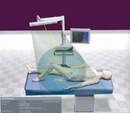
Drawing of setup in operating room, with system platform, computer and localizer camera aimed towards the patient on the table.
FIGURE 2.
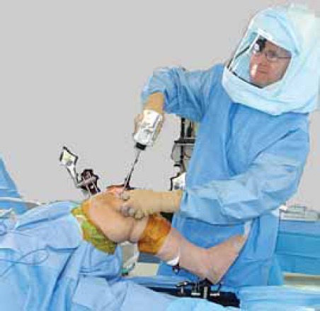
Jeffrey R.S., Morris R.W, Denham RA. Coronal alignment after total knee replacement.
FIGURE 3.
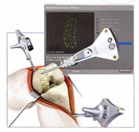
Mullholand S.Y., Wyss UP. Activities of daily living in non-Western cultures: range of motion requirements for hip and knee joint implants.
FIGURE 4.
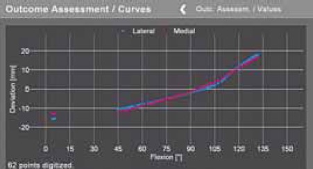
Preoperative kinematic curve. Balanced knee should have it more horizontal and blue and red line (medial and lateral joint width) should be parallel.
FIGURE 5.
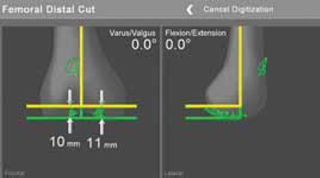
Femoral distal cut. Yellow line indicates position of the jig and cut, which should be neutral in AP and sagittal plane.
FIGURE 6.
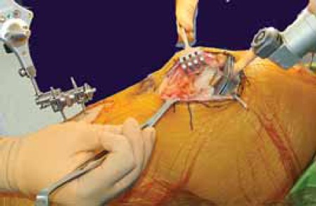
Intraoperative distal femoral cutting using low profile “J” jig
FIGURE 7.
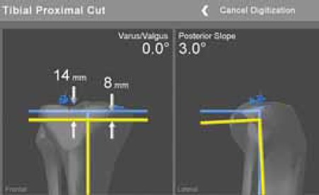
Tibial proximal cut, jig position is presented by yellow line.
FIGURE 8.
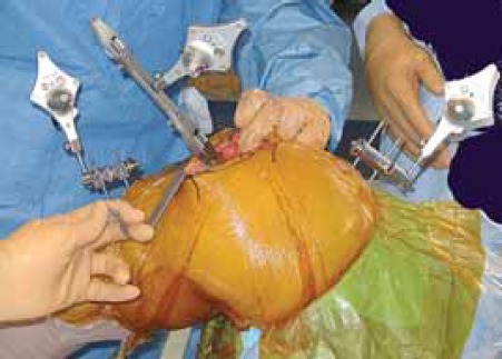
Tool (mobile) tracker is attached to tibial tray verifying the cut and tray rotatioa Femoral and tibial (fixed) trackers are in place.
KNEE ARTHROPLASTY
The goal of partial or total joint arthroplasty is to relieve the pain and improve long lasting function of the affected joint when non-operative measures were not able to alleviate the problems any more. In full extension the knee joint line should be perpendicular to the mechanical axis of the lower extremity (connecting centers of the hip, knee and the ankle) and the ground, close to it’s original height (no patella baja) and with well matching surfaces and rotations of components (especially femoral – no internal malrotation). The joint has to be balanced (symmetrical gaps in extension and flexion – slightly looser) and stable, allowing painless motion in range from 0 to 120 degrees (important for climbing the stairs) or up to 135 degrees (important for kneeling during prayers or cross-legged sitting) (3). Rand and Coventry (1988) found that survival rate of knee arthroplasty in 10 years was 90% if knee alignment was within 4 degrees of neutral, and in cases where deviation was more than 4 degrees revision was not required only in 73% varus knees, and 71% in valgus knees (1). Similar findings have been reported by Jeffrey at al (1991), with loosening rate of 24% if deviation was more than three degrees and 3% if deviation was within three degrees (2). How often do we encounter malalignment using the classical, manual instrumentation? Peterson and Engh (1988) looked at 50 randomly chosen cases from their casuistic and found that 26% of knees had more than 3 degrees of varus/valgus malpositioning (4). Another high volume center found similar problems in 25% of their 673 patients (5). Barrack (2001) had 10% of patients (out of 102) with anterior knee pain and combined internal rotation of 4,7 degrees (ranging from 17 degrees of internal rotation to 4 degrees of external rotation), and no pain in patients with a mean external rotation of 2,6 degrees (6). Chauhan at al (2004) did a prospective randomized controlled study, comparing navigation and manualjig based techniques in 70 patients. The Perth CT protocol was used for alignment verification. Significantly better results were found in navigated knees in next parameters: varus/valgus of the knee, femoral component rotation, varus/valgus of tibial component, tibial posterior slope and femurtibial components mismatch. Also, estimated blood loss was significantly less in the navigated group (no medullar canal opening) but navigated cases took on the average 13 minutes longer (80 minutes) (7). These results were confirmed by three other prospective randomized studies looking together at 500 patients without complication specifically related to navigation alone (8, 9, 10).
TECHNIQUE
After patient is anesthetized (usually with a regional anesthetic), patient knee joint is opened. Navigation minimizes the risk involved with MIS technique, there is no need to physically see or touch all important landmarks (like the lateral epicondyle). The usual MIS incision length is double the height of patella (skin tensions and pressures must be avoided, incision is lengthened as necessary). We need to make sure that the patella is mobile enough (mid-vastus approach) so that we have access to the joint surfaces. Femoral and tibial trackers are attached to corresponding bones, and rotational hip motion will determine the hip center. A pointer instrument is used to register transepicondylar axis, center of the femur, Whiteside anteroposterior (AP) line, femoral condyles and anterior cortex of the femur (Figures 2 and 3). On the tibial side center of tibial plateau (ACL insertion), neutral AP axis, medial and lateral articular surfaces, the medial and lateral malleolus with the ankle center are registered. From acquired data, the software creates images of the knee joint in different views (AP, lateral, cross-sectional) with present mechanical axis. The knee joint is put through the range of motion, and deformities (varus-valgus, maximal flexion and extension, contractures and laxities) are documented. Mobile tracker is attached to cutting blocks (“4 in 1” cutting block or J-jig,) and we are able to adjust and fix it in perfect position (femoral rotation, no anterior cortex notching, posterior tibial slope and rotation, and desired level of joint surfaces resection, Figures 5 and 6). Tibial side is resected immediately after the first femoral distal cut (to open the joint space using the guidance displayed on the monitor (Figures 7 and 8). After insertion of trial components, joint is tested for range of motion, stability – need for ligament balancing. Necessary adjustments (different poly thickness, additional cuts) are done with immediate, real time information displayed on the screen. If satisfied, final components are inserted (cemented or non-cemented, patella with or without resurfacing). Tourniquet, if used, is usually released after the implants are in place, and joint drain is not necessary. Minimally invasive technique (smaller incision, no averting patella, preserving the suprapatellar pouch, minimally resected retropatellar Hoffa tissue, lessening or avoiding tibial dislocation) is done with and without navigation. The results are more pleasing to patients; they have less immediate and first three months postoperative pain (comparing it with classical approach) and faster functional recovery. Procedure is less expensive because of shorter hospital stay (same day surgery for unicondylar knee replacement, and a couple of days after bicondylar replacement) (11-13). Preoperative patient education, specific pain control protocols (regional blocks such as epidural anesthesia and analgesia, regional femoral block, intra-articular pain pump, intra-articular injections of different “cocktails”, oral medications – NSAIDs, COX-2 inhibitors, narcotics), postoperative modalities (cold) and physical therapy play extremely important role in overall patient recovery, in hospital length of stay and general satisfaction.
HIP ARTHROPLASTY
Malpositioned acetabular cup may cause decreased range of motion with impingement, higher risk of dislocation and increased wear. Total hip dislocation (1% to 9%) is often devastating complication for the patient and his surgeon. It is more common in posterior approach, than in anterior or direct lateral approaches. Reasons for the different dislocation rates are multifactorial. (14, 15). Component position surely plays there a significant role. Biederman at al (2005) compared the position of acetabular component in 127 dislocated total hips with control of 342 patients without dislocation. They found that ideal cup position should have radiological abduction of 45 degrees and anteversion or flexion of 15 degrees in order to function well (16). There are few other studies confirming that safe cup position as 45 ± 10 degrees of abduction, and 15 ± 10 degrees of flexion (17, 18). The true position of the pelvis is hard to estimate due to unknown amounts of patient’s lordosis or kyphosis. Also, problem is that pelvic orientation changes (flexes and tilts anteriorly) in typical intraoperative lateral decubitus comparing it with pelvis in supine or standing position, or even comparing it to the position at the beginning of procedure (19). In revision situation often is very hard to find usual anatomical landmarks (columns, transverse acetabular ligament, Figure 9). Hassan at al (1998) reported that desired cup position can not be reached consistently when using conventional technique even by experienced surgeons in up to 42%. (17)
FIGURE 9.
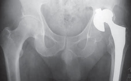
Pelvic x-ray with loose left acetabular cub, prosthesis head subluxation and distorted acetabular anatomy 14 years after primary joint replacement.
TECHNIQUE
Pelvic entrance plane is defined by anterior superior iliac spines and symphysis. There is a constant relationship of that imaginary plane and acetabulums. Using kinematic registration of plane’s landmarks (touching them with pointer), navigation allows for cup implantation in desired position independently on patient’s position on the table. Pelvic tracker is securely attached to the ipsilateral iliac crest or supra-acetabular bone and that position should not change at all. MIS approach of choice will expose piriformis fossa which will be registered, as well as center of popliteal fossa and Achilles tendon. Ranging the hip joint computer will register patient anatomy (hip center, leg length, offset). After femoral head and neck resection (for primary THA), “bone morphing”(with pointer) of the acetabulum inner wall, articular surface and rim is done. Attaching the mobile tracker to the reamer handle, it is possible to get positioned within one degree of desired abduction and anteversion (Figure 10). Also, the computer will warn the surgeon if we are approaching medial wall and there is a risk of penetration (Figure 11). The cup is introduced with navigation as well (Figure 12). After femoral preparation and implantation of trial components (Figure 13.), new kinematic registration is performed (ranging the hip). The values of the reconstructed joint will be display on the screen (length, offset, Figure 14). Putting the hip through maximal range of motion (flexion, extension, rotations, abduction – adduction), the surgeon is able to see at which positions impingement, lift-off or dislocation occur (Figure 15). Needed corrections are done accordingly including periacetabular bone removal, neck length adjustment, offset, femoral rotation, or cup reorientation if necessary, Figure 16). Haaker (2004) performed 100 navigated cases, consuming on average 90 ± 19 minutes. Cup position was 44,2 ± 9,6, anteversion 17 ± 3,5. They had no outliers, no complications and no dislocations (14). Large surgical exposures could improve direct orientation and help in position of components (Figure 17), but this can also account for higher number of wound problems. MIS in hip reconstruction is well developed today (Figure 18), and there are multiple reports with excellent results. Sculco (2005) had 684 total hip hybrid arthroplasties done through posterolateral incision with an average length 8,2 cm and dislocation rate of only 0,9%. (20) Di-Gioia at al (2003) compared MIS and classical navigated approaches. They found significantly better function with MIS technique regarding limping, stairs climbing and distance walking after three and six months and no difference in-between groups after one year (21). Lazovic at al (2005) compared 110 hips done with conventional technique to 127 navigated hips in prospective, randomized study. Navigated joints were significantly better regarding cup position and lack of dislocation. (22) This is also our experience (Figures 19 and 20).
FIGURE 10.
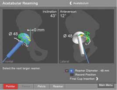
Graphie presentation of acetabular reamer in two views,
FIGURE 11.
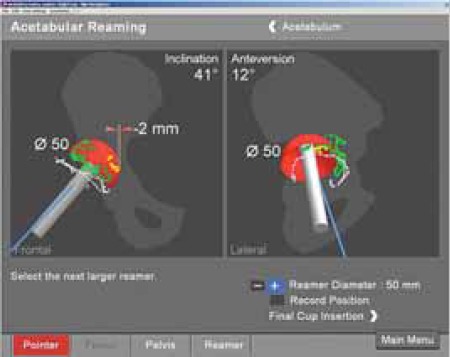
Penetration of medial wall for 2 millimeters in comparison with original wall registration.
FIGURE 12.
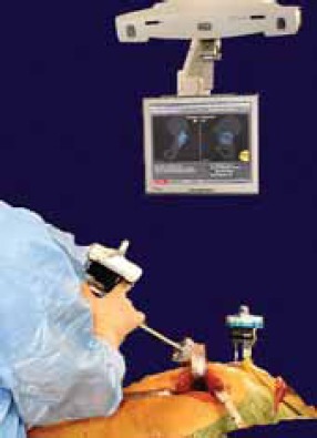
Tool tracker is attached to the handle holding the cup, and position is controlled by real time view on the monitor.
FIGURE 13.
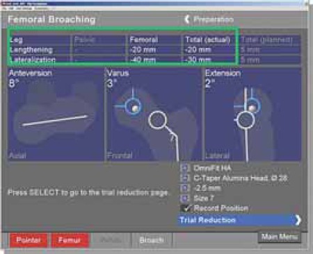
Information’s gathered during femoral broaching (from different patient).
FIGURE 14.
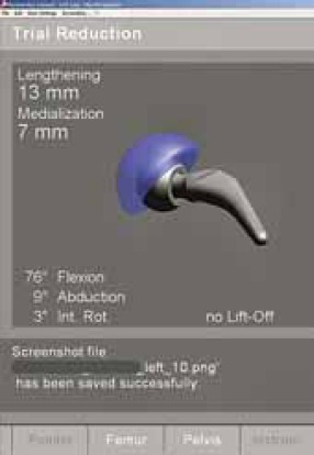
Display with range of motion and position of trial prosthesis.
FIGURE 15.
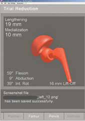
Dislocated joint, position of the prosthesis is graphically and numerically displayed.
FIGURE 16.
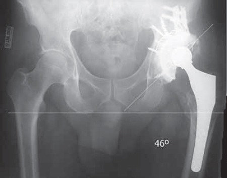
lhe final position of reconstructed hip with perfect cup abduction (cemented poly in antiprotrusio cage supported by impacted allograft bone).
FIGURE 17.
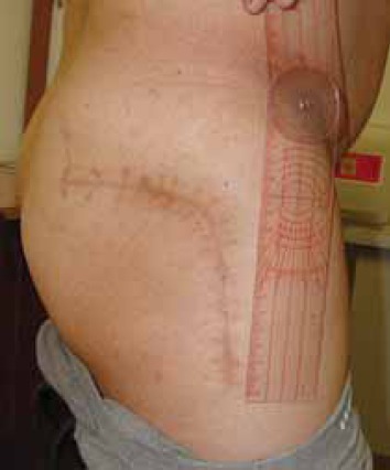
Clinical photo of 25 cm long classical incision in posterolateral approach.
FIGURE 18.
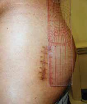
Clinical photo of MIS posterolateral approach incision long 6.5 cm (done 6 months after opposite hip surgery).
FIGURE 19.
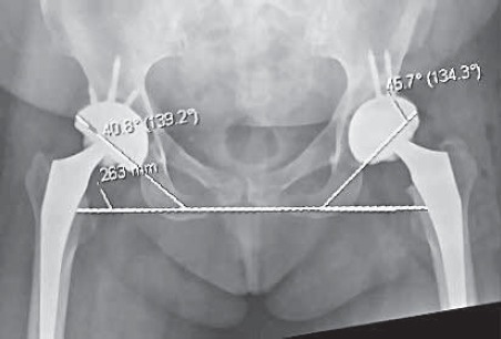
Pelvis AP view. Both cups are in safe range of abduction and navigated left hip is closer to ideal 45 degrees (although is done through smaller approach, MIS).
FIGURE 20.
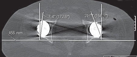
CT axial views show better cup anteversion on the left side (using navigation).
CONCLUSION
Computer navigation joint replacement allows for higher precision than what is possible using just classical, manual technique. Implants are aligned better and reconstructions are lasting longer. Minimally invasive approaches are sparing soft tissues facilitating faster recovery and shorter hospital stay. Combined together, CAOS and MIS are making patients and their surgeons happy. Navigation technology has been used in spine surgery (pedicular screws), fractures care (reductions, nailing, percutaneous screws in pelvic and hip surgery with minimal radiation), osteotomies and even ligamentous reconstructions (tunnel positioning for ACL and PCL grafts). New generations of young surgeons could be trained easier on computers even before they get to the operating rooms. Navigation is an excellent research tool. It will gradually become a routine technique used for the most of orthopaedic procedures.
REFERENCES
- 1.Rand JA, Coventry MB. Ten-year evaluation of geometric total knee arthroplasty. Clin. Orthop. Relat. Res. 1988;232:168–173. [PubMed] [Google Scholar]
- 2.Jeffrey RS, Morris RW, Denham RA. Coronal alignment after total knee replacement. J. Bone Joint Surg. Br. 1991;73-B:709–714. doi: 10.1302/0301-620X.73B5.1894655. [DOI] [PubMed] [Google Scholar]
- 3.Mullholand SY, Wyss UP. Activities of daily living in non-Western cultures: range of motion requirements for hip and knee joint implants. Int. J. Rehabil. Res. 2001;24:191–198. doi: 10.1097/00004356-200109000-00004. [DOI] [PubMed] [Google Scholar]
- 4.Petersen TL, Engh GA. Radiographic assessment of knee alignment after total knee arthroplasty. J. Arthroplasty. 1988;3:67–72. doi: 10.1016/s0883-5403(88)80054-8. [DOI] [PubMed] [Google Scholar]
- 5.Mahaluxmivala J, Bankes MJ, Nicolai P, Aldam CJH, Allen PW. The effect of surgeon experience on component positioning in 673 press fit Condylar posterior cruciate-sacrificing total knee arhroplasties. J. Arthroplasty. 2001;16:635–640. doi: 10.1054/arth.2001.23569. [DOI] [PubMed] [Google Scholar]
- 6.Barrack RL, Schrader T, Bertot AJ, Wofe MW, Myers L. Component rotation and anterior knee pain after total knee arthro-plasty. Clin. Orthop. Relat. Res. 2001;392:46–55. doi: 10.1097/00003086-200111000-00006. [DOI] [PubMed] [Google Scholar]
- 7.Chauhan SK, Scott RG, Breidahl W, Beaver RJ. Computerassisted knee arthroplasty versus a conventional jig-based technique. J. Bone Joint Surg. Br. 2004;86-B(3):372–377. doi: 10.1302/0301-620x.86b3.14643. [DOI] [PubMed] [Google Scholar]
- 8.Sparmann M, Wolke B, Czupalla H, Banzer D, Zink A. Positioning of total knee arthroplasty with and without navigation support. J. Bone Joint Surg. Br. 2003;85(6):830–835. [PubMed] [Google Scholar]
- 9.Bathis H, Perlick L, Tingart M, Luring C, Zurakowski D, Grifka J. Alignment in total knee arthroplasty. A comparison of computer-assisted surgery with the conventional technique. J. Bone Joint Surg. Br. 2004;86(5):682–687. doi: 10.1302/0301-620x.86b5.14927. [DOI] [PubMed] [Google Scholar]
- 10.Victor J, Hoste D. Image-based computer-assisted total knee arthroplasty leads to lower variability in coronal alignment. Clin. Orthop. Relat. Res. 2004;(428):131–139. doi: 10.1097/01.blo.0000147710.69612.76. [DOI] [PubMed] [Google Scholar]
- 11.Bonutti PM, Mont MA, McMahon M, Ragland PS, Kester M. Minimally invasive total knee arthroplasty. J. Bone Joint Surg. Am. 2004;86-A(Suppl 2):26–32. doi: 10.2106/00004623-200412002-00005. [DOI] [PubMed] [Google Scholar]
- 12.Dalury DF, Jiranek WA. A comparison of the midvastus and paramedian approaches for total knee arthroplasty. J. Arthroplasty. 1999;14(1):33–37. doi: 10.1016/s0883-5403(99)90199-7. [DOI] [PubMed] [Google Scholar]
- 13.Laskin RS, Beksac B, Phongjunakorn A, Pittors K, Davis J, Shim JC, Pavlov H, Petersen M. Minimally invasive total knee replacement through a mini-midvastus incision: an outcome study. Clin. Orthop. Relat. Res. 2004;428:74–81. doi: 10.1097/01.blo.0000148582.86102.47. [DOI] [PubMed] [Google Scholar]
- 14.Haaker R. The German experience with CAOS, data on THA. 71st AAOS Annual Meeting in San Francisco, CA. Proceedings. 2004:76–78. [Google Scholar]
- 15.Lewinnek GE, Lewis JL, Tarr R, Compere CL, Zimmerman JR. Dislocation after total hip-replacement arthroplasties. J. Bone Joint Surg. Am. 1978;60:217–220. [PubMed] [Google Scholar]
- 16.Biedermann R, Tonin A, Krismer M, Rachbauer F, Eibl G, Stockl B. Reducing the risk of dislocation after total hip arthro-plasty: the effect of orientation of the acetabular component. J. Bone Joint Surg. Br. 2005;87(6):762–769. doi: 10.1302/0301-620X.87B6.14745. [DOI] [PubMed] [Google Scholar]
- 17.Hassan DM, Johnston GH, Dust WN, Watson G, Dolovich AT. Accuracy of intraoperative assessment of acetabular prosthesis placement. J. Arthroplasty. 1998;13:80–84. doi: 10.1016/s0883-5403(98)90079-1. [DOI] [PubMed] [Google Scholar]
- 18.Pradhan R. Planar anteversion of the acetabular cup as determined from plain anteroposterior radiographs J. Bone Joint Surg Br. 1999;81:431–435. doi: 10.1302/0301-620x.81b3.9067. [DOI] [PubMed] [Google Scholar]
- 19.Eddine TA, Migaud H, Chantelot C, Cotten A, Fontaine C, Duquennoy A. Variations of pelvic anteversion in lying and standing positions: analysis of 24 control subjects and implications for CT measurement of position of a prosthetic cup. Surg. Radiol. Anat. 2001;23:105–110. doi: 10.1007/s00276-001-0105-z. [DOI] [PubMed] [Google Scholar]
- 20.Sculco TP. Minimally invasive total hip replacement. 72nd AAOS Annual Meeting in Washington, DC. Proceedings. 2005:28. [Google Scholar]
- 21.DiGioia AM, 3rd, Plakseychuk AY, Levison TJ, Jaramaz B. Mini-incision technique for total hip arthroplasty with navigation. J. Arthroplasty. 2003;18(2):123–128. doi: 10.1054/arth.2003.50025. [DOI] [PubMed] [Google Scholar]
- 22.Lazovic Dj, Kaib N. Results with navigated bicontact total hip ar-throplasty. Orthopedics. 2005;28(10)(Supp):s1227–s1233. doi: 10.3928/0147-7447-20051002-05. [DOI] [PubMed] [Google Scholar]


