Abstract
Objective:
Robotics-assisted retinal microsurgery provides several benefits including improvement of manipulation precision. The assistance provided to the surgeons by current robotic frameworks is, however, a “passive” support, e.g., by damping hand tremor. Intelligent assistance and active guidance are, however, lacking in the existing robotic frameworks. In this paper, an active interventional control framework (AICF) has been presented to increase operation safety by actively intervening the operation to avoid exertion of excessive forces to the sclera.
Methods:
AICF consists of four components: 1) the steady-hand eye robot as the robotic module; 2) a sensorized tool to measure tool-to-sclera forces; 3) a recurrent neural network to predict occurrence of undesired events based on a short history of time series of sensor measurements; and 4) a variable admittance controller to command the robot away from the undesired instances.
Results:
A set of user studies were conducted involving 14 participants (with 4 surgeons). The users were asked to perform a vessel-following task on an eyeball phantom with the assistance of AICF as well as other two benchmark approaches, i.e., auditory feedback (AF) and real-time force feedback (RF). Statistical analysist shows that AICF results in a significant reduction of proportion of undesired instances to about 2.5%, compared to 38.4% and 26.2% using AF and RF, respectively.
Conclusion:
AICF can effectively predict excessive-force instances and augment performance of the user to avoid undesired events during robot-assisted microsurgical tasks.
Significance:
The proposed system may be extended to other fields of microsurgery and may potentially reduce tissue injury.
Keywords: Medical robotics, recurrent neural network, retinal surgery, safety in microsurgery
I. Introduction
Retinal surgery is an excellent example of a high-demand dexterity procedure that may benefit from robotic systems. The procedures in retinal surgery involve manipulation of tissues on the micron scale, for which even single millinewton forces (below human tactile ability) [1] can lead to irreversible structural and functional damage. In a typical retinal procedure, a surgical microscope is used to provide a clear and magnified view of the interior of the eye for the surgeon. The surgeon inserts two or more small instruments (e.g. 25Ga, ϕ < 0.5mm) through the sclerotomy port (ϕ < 1mm) on the sclera, to perform delicate tissue manipulations on the eye. An example of retinal surgical tasks that remain challenging is retinal vein cannulation. which is an exploratory treatment for retinal vein occlusion. During retinal vein cannulation. the surgeon needs to pass and hold the needle or micro-pipette through the sclerotomy port and carefully insert it into the targeted retinal vein. After insertion, the surgeon needs to hold the tool steadily for as long as required for clot-dissolving drug injection to be carried out. At the sclerotomy port, the tool exerts continuous tool-to-sclera forces (scleral force) throughout the procedure. The outcomes of retinal surgery are impacted by many factors, including but not limited to surgeon physiological hand tremor, fatigue, poor kinesthetic feedback, patient movement, and the absence of force sensing. The risk of iatrogenic injury to the eye is therefore real.
The challenges of retinal surgery could be potentially reduced by robotic technology. Various robotic devices have been developed to enhance and expand capabilities of surgeons and to improve retinal surgery safety. Robotic prototypes were proposed prior to 2000 and these are the early robotic systems that laid the ground work for modern robot-assisted retinal surgery [2]–[5]. Subsequent systems are more advanced and are categorized as follows:
(a). Tele-operated:
In this category, the operator indirectly performs surgery through a master console device. Rahimy et al. [6] presented an intraocular robotic interventional and surgical system (IRISS). IRISS provides a large range of motion for instruments to perform eye surgeries in anterior segment (e.g., cataract) and posterior segment (e.g., vitreo-retinal surgery). The feasibility of IRISS was evaluated on porcine eyes. Wei et al. [7] developed a dual-arm robot, which consists of a 6-degree-of-freedom (DOF) parallel robot and a 2-DOF manipulator. The system was evaluated in microvascular stenting on chick chorioallantoic membranes and agar vascular models. Ueta et al. [8] developed a robotic manipulator using an arc-slider for retinal surgery. Their system also incorporated a 3-dimensional visual system. Xiao et al. [9] developed two manipulators aimed for retinal vein bypass surgery. The evaluation experiments were carried out in porcine eyes. He et al. [10] devised a two-arm robot system for retinal surgery, in which each arm consists of a SCARA robot. The feasibility of their system was evaluated on an eye phantom and in porcine eyes. Edwards et al. have developed improved clinically applicable robotic system. “Preceyes” [11], that has now been used successfully in human clinical trials. Gijbels et al. [12] developed a similar system that has successfully performed retinal vein cannulation in human patients, and can also be used as a hand-on device.
(b). Hands-on operated:
Unlike a tele-operated system, a hands-on operated device does not have a master console. Instead, it allows the user to hold any tool mounted on the system’s end-effector directly. An example of such systems is the Steady-Hand Eye Robot (SHER) developed at Johns Hopkins University (JHU) [13]. SHER allows the user to directly hold the tool mounted on SHER’s end-effector to perform tasks. The forces applied by the user’s hand to the tool handle is captured by a force/torque sensor at SHER’s end-effector in a real-time manner, and is used to compute SHER’s velocity. In addition to increased steadiness and accuracy, direct instrument manipulation provided by the SHER is potentially helpful in averting injury when instantly removing the instrument from patients eye is required.
(c). Hand-held:
As stand-alone devices, such systems have the benefits of being lighter and more portable than robotic platforms. MacLachlan et al. [14] developed “Micron”, a hand-held tool that reduces tremor by actuating the tip to counteract the effect of any undesired low-amplitude and high-frequency motions such as hand tremors. Hubschman et al. [15] proposed a flexible micro-forceps, Micro-hand, which is able to apply calibrated forces to ocular tissues. He et al. [16] presented a sub-millimeter intraocular dexterous device aimed at enhancing surgeon dexterity within the vitreous cavity. These systems can also be mounted as end-effectors on a robotic platform.
(d). Untethered:
Kummer et al. [17] designed a fully untethered microrobot using a wireless magnetic control scheme. The intraocular microrobot could be actuated by the electromagnetic system for delicate retinal procedures.
In addition to reducing tremor and enhancing precision, the above-mentioned platforms can be equiped with sensors to improve tactile and force perception of surgeons. Optical sensors with high resolution, enhanced sensitivity, and reduced size are potentially usable in retinal environments. Yu et al. [18] designed an optical coherence tomography (OCT) guided forceps, which could provide real-time intraocular visualization of retinal tissues as well as the distance between the tool tip and tissue. Song et al. [19] developed an OCT-based forceps to detect the contact between forceps tip and retina. A JHU research group developed microsurgical instruments based on Fiber Bragg Gratings (FBG) sensors to measure not only transverse [20], and axial force at the tool tip [21], but also the location and amount of force on the tool shaft [22]. The collective body of work implies that force sensing may be a useful strategy for understanding the forces on instruments during prototypical maneuvers, and a first step towards preventing undesirable tissue damage as a result of tool-tissue interactions.
Force sensing may also be used to provide feedback to improve surgeon awareness. AF [23] is based on the emission of audio responses to specific force levels measured by the sensing tool, indicating risk of damage to the retina. Haptic feedback based on RF [24], on the other hand, relies on restricting instrument movement in response to the breaching of a prescribed force limit. Due to an incomplete understanding of a surgeon’s imminent intentional manipulations, existing systems can only enhance the safety in a passive way, i.e., without predicting and/or preventing unintentional maneuvers by the surgeon. Therefore, potential damage to the eye tissue during surgery remains a concern, while passive feedback systems are insufficient to prevent injuries.
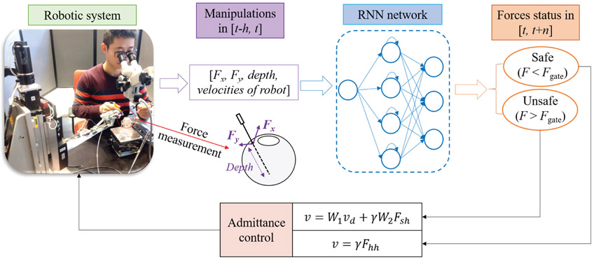
Therefore, in this paper, a novel active system, AICF, is presented to enable prediction and prevention of unintentional and potentially risky maneuvers of the surgeon. It should be noted that the system is considered active in the sense that it actively interferes with the task when necessary in a predictive and intelligent manner, rather than in a passive manner by only damping the motion after the undesired event occurs. Fig. 1 shows the overall scheme of the proposed framework. The framework consists of a force sensing tool with FBG attached to the SHER’s end- effector, an RNN predictor, and an adaptive admittance controller. To design the RNN, the measurements from the FBG sensors along with velocity of the robot’s end-effetor and the insertion depth of the tool inside the eyeball are used. The data is fed into an RNN with long short-term memory (LSTM) units to predict undesired instances in terms of forces at the scleral port. When an undesired instance is predicted by the RNN, the adaptive admittance controller then actuates the SHER to partially interrupt the user maneuvers and perform compensatory motions to prevent the excessive range of scleral forces.
Fig. 1.
Overview of the AICF consisting of a force sensing tool, an RNN predictor, an admittance control system, and the SHER research platform. The robotic manipulator is activated to move at a varying speed in order to decrease the resulting scleral forces. Fx and Fy are the two components of the scleral force measured by the force sensing tool. W1, W2, and γ are the parameters of the admittance controller, Fsh and Fhh are the maneuver forces applied by the user resolved in different coordinate system.
Preliminary evaluation of the AICF was discussed previously in a conference paper [25]. The results reported in [25] was only a pilot phase with 3 users and a network model trained with a limited sets of data. In the current version, the network has been updated using an extended dataset collected from multiple users. In addition, a new variable admittance controller is applied, and the AICF is evaluated in a multi-user study involving 14 users (including 4 retinal clinicians). A more realistic surgical task was also chosen. The users were asked to perform a ”vessel following” task, which is a typical operation in retinal surgery, with two hands on en eye phantom, in which the eyeball can freely rotate. The users performed the task in 3 cases: with the assistance of AICF, as well as two other benchmark approaches (AF and RF). The results show statistically significant superior performance of the AICF compared to AF and RF in keeping the scleral force within the safety limits.
II. Active interventional control framework
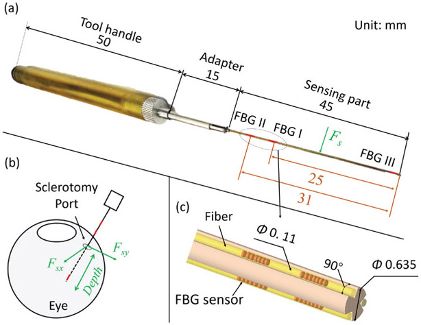
As mentioned above, the AICF consists of four components: a force sensing tool, an RNN, a variable admittance control system, and the existing SHER. The force sensing tool has been previously shown to measure the scleral force and the insertion depth as shown in Fig. 2. Installed within the force sensing tool, FBG sensors provide strain measurements at a given segment of the tool shaft. Based on the strain measurements, the insertion depth and the scleral force are then calculated using the calibration algorithm presented in [22]. Root Mean Square (RMS) errors of the scleral force and the insertion depth were 2.1 mN and 0.3 mm, respectively. In the following subsections, the proposed RNN and the variable admittance controller are discussed:
Fig. 2.
Overall scheme of the force sensing tool: (a) The overall dimensions of the tool. The sensing part contains nine FBG sensors, which are located on three segments along the tool shaft; (b) Illustration of the measurements provided by the force sensing tool. The scleral force is the contact force between the tool shaft and the sclerotomy port. The insertion depth is the depth of the tool tip’s penetration into the eye; (c) A close-up view of the layout of the FBG sensors.
A. RNN predictor
Magnitude of the sclera force is affected by many factors, including the surgeon’s and patient’s movements, friction between the instrument and the scleral port, and scleral port deformation. The uncertainty inherent in these parameters makes scleral force modeling challenging for classical predictors, such as Kalman filters [26], a dynamic method that depends on the state model. However, model-free methods, i.e., neural networks, have been shown to have significant advantages in handling such high-dimension modeling problems [27]. Based on efficiency in modeling such parameters, neural networks were adopted as the prediction model in this paper.
1). RNN architecture design:
Classical RNN models are described to have vanishing-gradient problem when trained with back propagation through time due to their deep connections over long periods [28]. To overcome this problem, LSTM model [29] was proposed to capture long-range dependencies, nonlinear dynamics, and to model varying-length sequential data, achieving state-of-the-art results for problems spanning clinical diagnosis [30], image segmentation [31], and language modeling [32]. In this study, it is assumed that the scleral force characteristics can be captured through a short history of time series of sensor measurements. This assumption is made considering the relatively slow dynamics of human arm motion, especially during microsurgical procedures. An RNN network with LSTM unit is then constructed to make predictions about the scleral force status based on the history. Fig. 3 shows the overall scheme of the RNN architecture developed for this purpose. The network includes a fully connected layer (FC) atop the LSTM layer followed by an element-wise softmax activation function to perform multilabel prediction.
Fig. 3.
The proposed RNN architecture. The input is a short history (h time steps) of the scleral forces, the insertion depth, and the velocities of the robot’s end-effector. The outputs are the probabilities of the four labels which represent the scleral force status at the time t+n, where t is the current timestep; the label with the highest probability is selected as the final output.
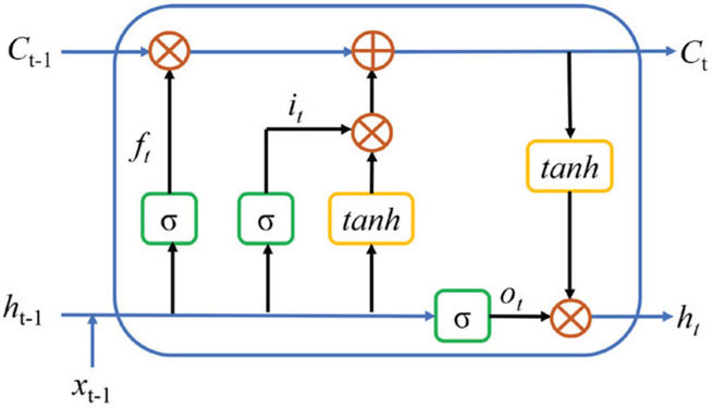
Similar to the LSTM architecture presented in [30], in this paper, the LSTM architecture is based on the memory cells and is composed of four main elements: one input gate, one forget gate, one output gate, and one neuron with a self-recurrent connection (a connection to itself). The gates serve to modulate the interactions between the memory cell itself and its environment. The input gate controls whether the current input should flow into the memory, and the output gate decides whether the current memory state should be passed to the next unit. The forget gate controls whether the memory should be kept. This LSTM unit data flow is shown in Fig. 4.
Fig. 4.
The data flow in the LSTM unit. xt−1 denotes input data. ft,it,ot are the forget gate, input gate, and output gate, respectively. Ct and ht are the current memory state and hidden state passing to the next unit. σ and tanh are sigmoid and hyperbolic tangent activation functions, respectively. ○ denotes point-wise operation.
The scleral force, the insertion depth, and the robot kinematic velocities of past h timesteps are fed into the RNN as the input; the RNN outputs the probabilities of the scleral force status in the t+n timesteps, labeled as 0, 1, 2, and 3 and generated using Eq. 1.
| (1) |
where Fgate is the safety threshold of the scleral force and is set as 100 mN based on the results of our previous work [33]. The label designated as 0 represents safe force status, while the one assigned as 1, 2, or 3 denotes excessive-force status. Fx(t)* and Fy(t)* are the maximum scleral forces within the prediction time window [t, t+n] as shown below:
| (2) |
| (3) |
where ∣·∣ denotes the absolute value.
The probability of each label is normalized by the softmax layer as shown in Eq. 4.
| (4) |
where xi is the output of FC layer, pi is the normalized probability, and M = 4 denotes the number of the labels. The label with the highest probability is selected as the final force status that is then sent to the robot control module.
2). RNN training:
To train the RNN the sensor measurements were collected from six users performing a given task. The measurements included scleral force, insertion depth, and robot end-effector velocities. The task was to follow a target that simulates a retina vessel. This is a common movement in vitreoretinal surgery and is further described in section III-B. The ground truth labels were generated using the scleral forces based on Eq. 1. The collected data was divided into two parts: training and testing. Cross-validation and random search were applied to specify a suitable set of the hyper-parameters, including the network size and depth, and the learning rate. Consequently, the learning rate was chosen as a constant value of 2e-5, and the LSTM layer was set with 100 neurons. The Adam optimization method [34] was used as the optimizer, and cross entropy (given in Eq. 5) was chosen as the loss function.
| (5) |
where yi is binary indicator (0 or 1) of the label i; pi is the predicted probability of the label i; and M = 4 denotes the number of labels.
During network training, the sequences of the dataset was not shuffled to allow the network to learn the sequential relations between the inputs and the outputs. Dropout method did not show significant performance improvement in this case, and therefore, was not used in the final design of the architecture. The training dataset was split into mini-batches of sequences of size 500, and normalized to the range of [0, 1]. The LSTM layer and the stacked LSTM layers were tested to specify proper network depth. The FC RNN was also tested as the benchmark model. In addition, RNN models were provided with different formats of dataset in order to find the best input data format, including vanilla value, derivative value, absolute derivative value, and absolute value. The network was implemented using Keras [35], a high-level neural networks application program interface (API). Training was performed on a computer equipped with Nvidia Titan Black GPUs, a 20-core CPU, and a 128GB RAM. Single-GPU training takes around 4 hours.
Performance of the various RNN models is shown in Table I. Accuracy denotes the true positive, and success rate represents the prediction results without the false negatives. Models with LSTM as architecture had better performance than the other ones with stacked LSTM or FC RNN; and models with the absolute value as an input resulted in superior performance as compared to those with other type of input format. Therefore, the model combining an LSTM architecture and having an absolute value input was chosen. The range of prediction times was also evaluated as a tradeoff between the higher prediction success rate and a longer forecasting time, with the value of 200 ms applied. The selected model has 87% accuracy and takes 10 milliseconds to produce a single prediction force status, which has negligible effect on the promptness of the prediction.
TABLE I.
Performance of the networks
| Model | Input data | Prediction window | Accuracy | Success rate | System elapsed time/one prediction |
|---|---|---|---|---|---|
| LSTM + FC | Vanilla value | 100 ms | 85% | 88% | 10 ms |
| LSTM + FC | Derivative value | 100 ms | 62% | 63% | 10 ms |
| LSTM + FC | Absolute derivative value | 100 ms | 70% | 76% | 10 ms |
| LSTM + FC | Absolute value | 100 ms | 89% | 90% | 10 ms |
| FC RNN + FC | Absolute value | 100 ms | 86% | 89% | 10 ms |
| Stacked LSTM + FC | Absolute value | 100 ms | 87% | 89% | 26 ms |
| LSTM + FC | Absolute value | 200 ms | 87% | 89% | 10 ms |
| LSTM + FC | Absolute value | 300 ms | 82% | 87% | 10 ms |
| LSTM + FC | Absolute value | 400 ms | 78% | 82% | 10 ms |
B. Admittance control method
A variable admittance control scheme is adopted on the basis of our previous velocity-level admittance control method [36]. During operation, both the user and the robot hold the tool; interaction forces of the user’s hand applied on the robot handle is measured and fed as the input into the admittance controller as follows:
| (6) |
| (7) |
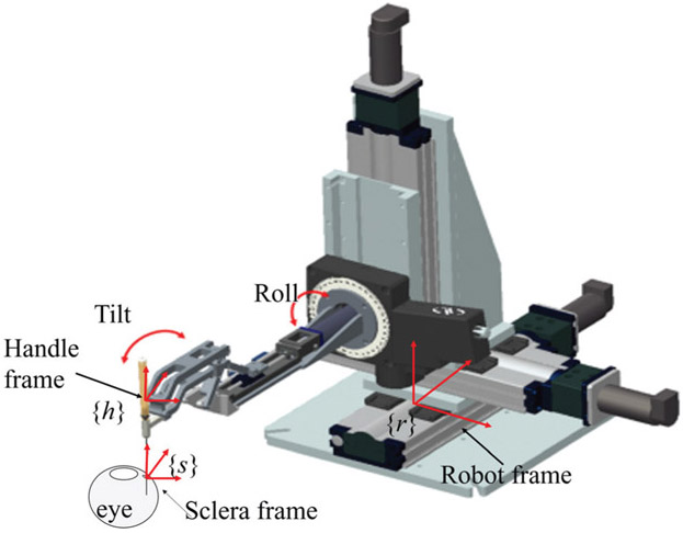
where vhh and vrh are the desired robot handle velocities in handle frame and robot frame, respectively (shown in Fig. 5). Fhh is the manipulation force applied by the user and measured in the handle frame, γ is the admittance gain adjusted by the user in real-time through a foot pedal. Adgrh is the adjoint transformation from the handle frame to the robot frame, which can be written as: , with Rrh as the rotation matrix and prh as the translation vector of the rigid transformation from the handle frame at the robot Cartesian frame; and is the skew symmetric matrix that is associated with the vector prh. The above-described method is adopted as the normal controller when the predicted scleral forces is in the safe status (prediction label = 0).
Fig. 5.
Illustration of the coordinate frames. The sclera frame denoted as {s} is located at the sclerotomy port, the handle frame denoted as {h} is located at the tool handle, and the robot frame denoted as {r} is located at the robot base.
The control scheme is switched to the interventional mode when the predicted scleral forces are specified as excessive (prediction label = 1, 2, 3). In this mode, the related components of the tool velocity in the sclera frame are assigned a desired value to reduce the scleral force. Force from the user’s manipulation in scleral frame is calculated based on Eq. 8:
| (8) |
where Fsh is the user’s hand force in the scleral frame, Adgsh is the adjoint transformation from the handle frame to the sclera frame, which can be written as , with Rsh as the rotation matrix and psh as the translation vector of the rigid transformation from the sclera frame at the sclera to the robot Cartesian frame; and is the skew symmetric matrix associated with the vector psh.
The desired velocity of the tool at the scleral frame vss is assigned as Eq. 9:
| (9) |
where W1 and W2 are diagonal admittance matrices and are dependent on the predicted status:
| (10) |
| (11) |
vd is the desired compensational velocity to reduce scleral force, given as follows:
| (12) |
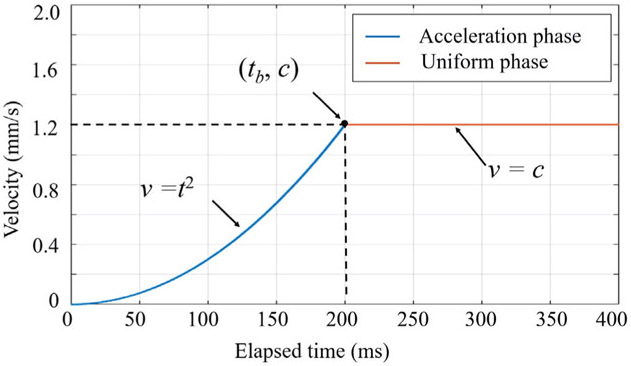
where tx and ty are the elapsed time of AICF activation activation along X direction and Y direction, respectively. tb and c are the parameters tuning the profile of the desired velocity as shown in Fig. 6. The desired velocity profile has two phases: an acceleration phase and a uniform phase. Quadratic polynomial was chosen for the acceleration phase in order to provide gradual transition in velocity during introduction of small negative effects on intuitiveness of surgeon’s maneuvers. Based on experimental evaluations, tb is set to 200 ms and c is set to 1.2 mm/s.
Fig. 6.
Desired velocity trajectory that consists of two phases: acceleration phase and uniform phase. Here only the positive part of the trajectory is illustrated.
Lastly, the tool velocity is resolved in the robot frame based on Eq. 13:
| (13) |
where , with Rrs as the rotation matrix and prs as the translation vector of the rigid transformation from the sclera frame to the robot Cartesian frame; also is the skew symmetric matrix that is associated with the vector prs.
III. Multiuser experiments
A. Experimental setup
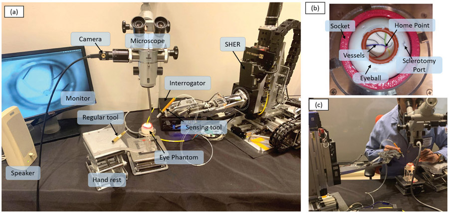
The experimental setup is shown in Fig. 7 (a). The force sensing tool was mounted on the end-effector of the SHER. The FBG interrogator (SI 115, Micron Optics Inc., GA USA) was utilized to collect FBG sensor readings at a 2 kHz refresh rate. An eye phantom was developed using silicon rubber, and placed into a 3D-printed socket as shown in Fig. 7 (b). The eye phantom can freely rotate, mimicking the human eyeball. A printed paper with several curved lines representing the retinal vessels was glued on the eyeball inner surface as targets. The curved lines were painted with different colors, and all lines intersected at the central point called “home” point, representing the optic disc. A binocular microscope (ZEISS, Germany) was utilized to provide a magnified view of the target and inner part of the eyeball. A Point Grey camera (FLIR Systems Inc., BC, Canada) was attached on the microscope for recording purpose. A monitor was used to display the camera view for assistance purposes.
Fig. 7.
The experimental setup: (a) The overall layout of the experimental setup. (b) The eyeball phantom, which is made of sillicon rubber and can freely rotate around the socket; a printed paper with several colored curves attached on the inner surface of the eyeball to mimic the arteries on the retinal surface. (c) An example of a user manipulating the tool.
B. Experimental procedure
The task was to follow the printed path inside the phantom with the instrument tool-tip as closely as possible, but without touching it. This is a common task during vitreoretinal surgery, named here as “vessel following” and was adapted to evaluate AICF. Vessel following consisted of 6 phases: (1) move the tool to approach the sclerotomy port, (2) insert the tool into the eyeball through the sclerotomy port until the tool tip reached the home point, (3) handle the tool to trace one of the paths with the tool tip from the home point to the end of the curve, (4) retrace the curve backwards to the home point, (5) retract the tool from the sclerotomy port, and (6) move the tool away from the eyeball. The users were instructed to perform the task by their dominant hand, which was supposed to control the force sensing tool and SHER. The user’s non-dominant hand was used to handle a regular tool (e.g., light pipe) to simulate a real experiment and to keep the eyeball in a usual orientation. The procedure was performed under the magnified view provided by the microscope, as shown in Fig. 7 (c), to better simulate an actual procedure.
C. User study protocol
Approved by the the Homewood Institutional Review Board, this study recruited 14 volunteers among JHU employees, including 4 retinal surgery clinicians and 10 graduated engineering students with expertise levels shown in Table II. The experiments were carried out at the Laboratory for Computational Sensing and Robotics, JHU, Baltimore, MD, USA. A consent form was signed by each participant before performing the experiment. Users were asked to perform the vessel-following task 10 times with the assistance of the ARIS. During the same session, the same procedure was also performed under two benchmark conditions: one with AF, and one with RF. Under AF condition, the user was provided with a “beep” sound if the scleral force breached the safety threshold [23]. Under RF condition, the SHER’s control mode switched to the interventional mode (as shown in Eq. 9) if the instantaneous scleral force increases to excessive status [24]. The three conditions were carried out in a randomized manner for each user. Latin square was used to generate the conditions sequence. The scleral forces applied by the user during the task were recorded for further analysis. Prior to data collection, users practiced manipulating the SHER for at least 10 minutes to familiarize themselves with its operation. At the end of data collection, users were asked to subjectively rate, on a scale of 1 (very well) to 5 (not at all), how well each operation mode assisted with task performance.
TABLE II.
Skills level of the users
| Category | Surgical skills | User numbers |
|---|---|---|
| Expert clinician | Over 20 years surgery experience | 1 |
| Clinician | Less than 1 year surgery experience | 3 |
| Non-clinician | No surgery experience | 10 |
IV. Results and discussion
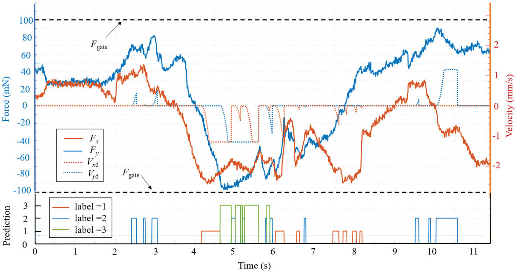
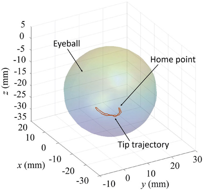
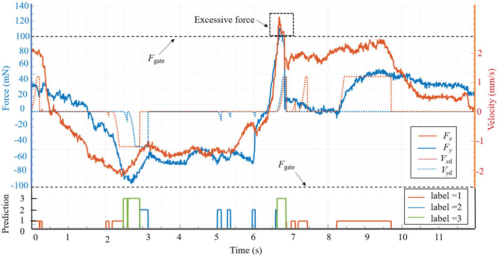
The intervention effect of AICF on the scleral forces is depicted in Fig. 8. When an excessive force status is predicted (label = 1, 2, 3), the scleral force is suppressed in the related direction by AICF, thus preventing it from breaching the prescribed safety boundary. The tool tip trajectory during this operation in the robot frame is shown in Fig. 9.
Fig. 8.
A successful example of AICF intervention on the scleral force. When the label is 0, AICF is inactive; when the label is 1, 2, or 3, AICF is activated and the desired velocity of the tool at the sclera frame (Vxd, Vyd) is assigned; and as the result, the scleral force (Fx, Fy) is reduced to remain within the safety boundaries (Fgate).
Fig. 9.
An example of the tool tip trajectory in the vessel-following task.
To quantitatively evaluate the feasibility of AICF, four metrics were used:
the maximum force values applied to the scleral port along X and Y axes, denoted by max (Fx, Fy),
total duration of the task, denoted by T,
duration of forces beyond the desirable range, denoted by T0,
duration proportion of the excessive forces to the total time, i.e., T0/T (×100%).
Furthermore, to evaluate real-time performance of the RNN model, the prediction success rate, α, is evaluated:
| (14) |
where tf is the duration of failed capture, during which the scleral force exceeded the prescribed safety boundaries while the predicted label was 0 referring to a safe status. ts is the AICF activation duration for labels 1, 2, and 3, during which AICF successfully captured the excessive forces.
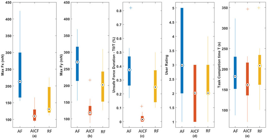
The above metrics were calculated for each user as shown in Table III. Statistical analysis was also conducted to compare performance between the three experimental cases: AICF, RF, and AF. The Mann-Whitney U test was performed to statistically evaluate the results. Fig. 10 shows the boxplot of the metrics calculated for the three experimental cases. Using the proposed AICF approach, max Fx (Fig. 10 (a)) and max Fy (Fig. 10 (b)) were decreased to 117.64 mN and 125.45 mN in a statistical manner compared to:
TABLE III.
Multiuser evaluation results
| User | Metrics (unit: mN, S) |
Experimental conditions | User | Metrics (unit: mN, S) |
Experimental conditions | ||||
|---|---|---|---|---|---|---|---|---|---|
| AF | RF | AICF | AF | RF | AICF | ||||
| #1 | max (Fx, Fy) | (165.1,236.4) | (140.5,151.7) | (109.8,119.0) | #8 | max (Fx, Fy) | (192.4,213.8) | (196.7,168.2) | (144.2,111.8) |
| T | 87.2 | 100.6 | 71.2 | T | 196.9 | 234.3 | 215.9 | ||
| T0 | 34.2 | 20.2 | 1.8 | T0 | 50.2 | 93.3 | 11.8 | ||
| T0/T | 39.4% | 20.1% | 2.5% | T0/T | 25.5% | 39.8% | 5.5% | ||
| α | – | – | 100% | α | – | – | 99.4% | ||
| #2 | max (Fx, Fy) | (378.4,321.3) | (120.7,193.3) | (104.3,143.0) | #9 | max (Fx, Fy) | (155.4,157.0) | (118.5,129.8) | (92.7,110.9) |
| T | 230.0 | 203.2 | 174.0 | T | 149.4 | 161.7 | 135.7 | ||
| T0 | 187.9 | 102.5 | 6.3 | T0 | 24.9 | 22.9 | 0.4 | ||
| T0/T | 81.7% | 50.4% | 3.6% | T0/T | 16.7% | 14.2% | 0.3% | ||
| α | – | – | 100% | α | – | – | 100% | ||
| #3 | max (Fx, Fy) | (226.9,368.9) | (114.4,135.9) | (118.7,121.5) | #10 | max (Fx, Fy) | (396.4,281.8) | (181.2,240.4) | (92.5,97.7) |
| T | 185.9 | 250.3 | 215.7 | T | 218.4 | 185.1 | 102.7 | ||
| T0 | 71.4 | 33.4 | 1.5 | T0 | 79.4 | 40.0 | 0 | ||
| T0/T | 38.4% | 13.3% | 0.7% | T0/T | 36.3% | 21.6% | 0% | ||
| α | – | – | 99.7% | α | – | – | 100% | ||
| #4 | max (Fx, Fy) | (165.0,352.7) | (123.0,166.9) | (105.8,138.6) | #11 | max (Fx, Fy) | (423.9,274.5) | (216.2,309.2) | (129.7,216.4) |
| T | 323.4 | 349.1 | 346.6 | T | 243.0 | 245.7 | 136.3 | ||
| T0 | 85.7 | 85.5 | 1.0 | T0 | 127.5 | 90.2 | 8.9 | ||
| T0/T | 26.5% | 24.5% | 0.3% | T0/T | 52.5% | 36.7% | 6.58% | ||
| α | – | – | 100% | α | – | – | 100% | ||
| #5 | max (Fx, Fy) | (165.5,154.7) | (156.5,266.9) | (95.2,87.9) | #12 | max (Fx, Fy) | (243.6,316.4) | (224.9,226.1) | (165.9,122.2) |
| T | 168.9 | 132.8 | 138.8 | T | 136.8 | 126.5 | 107.4 | ||
| T0 | 43.3 | 31.9 | 0 | T0 | 59.1 | 32.9 | 1.7 | ||
| T0/T | 25.6% | 24.0% | 0% | T0/T | 43.2% | 26.0% | 1.5% | ||
| α | – | – | 100% | α | – | – | 99.9% | ||
| #6 | max (Fx, Fy) | (197.7,219.7) | (122.1,241,9) | (124.0,112.4) | #13 | max (Fx, Fy) | (299.7,265.9) | (200.4,208.1) | (159.3,160.4) |
| T | 176.9 | 212.9 | 203.7 | T | 161.6 | 211.0 | 145.5 | ||
| T0 | 47.6 | 87.7 | 7.2 | T0 | 83.9 | 67.5 | 15.2 | ||
| T0/T | 26.9% | 41.1% | 3.5% | T0/T | 51.9% | 32.0% | 10.5% | ||
| α | – | – | 99.8% | α | – | – | 99.5% | ||
| #7 | max (Fx, Fy) | (246.9,184.2) | (112.0,126.0) | (96.4,97.9) | #14 | max (Fx, Fy) | (195.0,302.2) | (123.7,264.0) | (108.5,116.7) |
| T | 277.4 | 193.3 | 230.9 | T | 151.6 | 222.4 | 208.7 | ||
| T0 | 73.2 | 18.9 | 0 | T0 | 71.7 | 32.1 | 1.75 | ||
| T0/T | 26.4% | 9.7% | 0% | T0/T | 47.2% | 14.4% | 0.8% | ||
| α | – | – | 100% | α | – | – | 99.9% | ||
Fig. 10.
Boxplot of the metrics for three experimental conditions: (a) max Fx; (b) max Fy; (c) excessive force duration percentage T0/T; (d) user rating; and (e) task completion time.
RF mode with force values of 153.62 mN and 202.02 mN (p-values = 0.0061 and 0.0001 for max Fx and max Fy, respectively); and
AF mode with force values of 246.56 mN and 260.67 mN for max Fx and max Fy, respectively (p – values << 0.001).
A statistically significant reduction in the proportion of excessive force was also observed using the AICF with the value of 2.5%, as compared to 38.4% using AF and 26.2% using RF modes (p – values << 0.0001 for both cases). The results indicate effectiveness of the AICF in increasing safety level of robot-assisted simulated retinal surgery by reducing the undesired forces applied to the scleral port by the surgical tool. Similar completion time was observed among three modes as shown in Fig. 10 (e). The result indicates that the users maneuver speed did not have significant changes in three experimental modes.
The robotic surgical assistance platforms currently available reduce tremor and enhance precise motions, providing surgeons with increased ability to perform delicate procedures. Examples of these include but are not limited to retinal vein cannulation [12], and macular membrane peeling [11]. Limitation of these platforms includes the stiff mechanical structure of robot manipulators that degrades tactile perception of the surgeon and introduces potentially injurious tool-to-tissue forces [33]. AF has been shown to modulate surgeon behavior in the specific area of force application [23], however prolonged auditory feedback may be subject to “tune out” by the operator. This may serve as a partial explanation for why T0/T in the AF group is higher than in the other two groups. RF could potentially provide enhanced support to surgeons as compared to auditory feedback alone, through actuating robotic manipulators to counteract undesired events. However, the protective algorithms are activated only after excessive forces occur in RF, therefore T0/T would still remain high (the maximum T0/T in RF group was 50.4%). By comparison, implementation of AICF may eliminate undesired events in advance, by predicting the surgeon’s manipulations in a short future time frame, and then feeding this predictive information into the robot’s control system for an appropriate response. Therefore, the T0/T in the AICF group is reduced considerably (10.5% maximum in worst cases and 0% in best cases).
The AICF approach also resulted in statistically significant lower user ratings, where a lower rating indicates a higher rate of assistance provided by the system. The subjective user ratings dropped to 1.92 using the AICF as compared to 3.35 using the AF (p-value = 0.0028). No statistically significant difference was observed for user ratings between assistance levels provided by AICF and RF. Using AF, however, the users can get distracted by the warning beep sounds. The predictive behavior of the AICF also results in an ahead-of-time activation of intervention motion, reducing the sudden impact of the safety algorithm as compared to in RF.
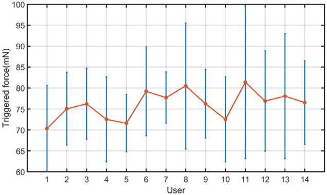
In addition, using the AICF, the prediction success rate, α, was above 99.4%, indicating capability of the proposed RNN model in capturing undesired events with high confidence. Fig. 12 shows the average “triggered” force values at which the AICF was activated for each user. As can be seen, for all the users, the activation has happened before the scleral force values reaches the safety threshold of 100 mN, indicating prediction capability of the AICF approach as a result of the proposed RNN model.
Fig. 12.
Trigger forces of AICF. The averaged absolute values of the trigger force (orange) are shown here as well as the standard deviations (blue). The AICF is activated before the scleral force reaches safety threshold.
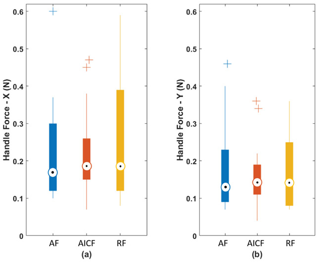
AICF deals with the excessive forces by partial active intervention at the level of the robot control system, thereby, interfering directly with the tool manipulation of the surgeon. Although the user’s maneuvers may be affected, the AICF interference takes limited control in only one or two directions and for a brief period of time (on the order of milliseconds). By being minimally intrusive, the human user still controls the robot and is able to continue the procedure with minimal awareness of robotic intervention. In the same time, due to in-advance and soft activation of the force reduction mechanism, AICF potentially may not produce a sudden force-blocking behavior during user’s operation. In evaluating this effect, we analyzed the averaged force applied to the tool handle (handle force) from all users, as plotted in Fig. 13. The force components of the handle force were measured to be very close regardless of the method of control, indicating relative consistency of force exertion profile of the users between the three experimental modes. This consistency of the handle forces, compared to baseline AF mode (where no force-based interaction is made by the system to prevent excessive forces), shows that the AICF does not significantly affect the user force exertion profile, and the maneuver transparency felt by the user is not degraded by the AICF.
Fig. 13.
Boxplot of the handle forces: (a) handle force along X axis; and (b) handle force along Y axis.
Although AICF is activated in advance when the scleral force is smaller than the threshold, the soft activation force reduction mechanism (as shown in Fig. 6) may take a few milliseconds to reduce the scleral force, which may cause a lag and result in the force continuing growing and breaching the safety limit especially when the force has a big gradient, as shown in Fig. 11. Also, the experimental task, i.e., vessel following, was a bimanual operation: users dominant hand manipulated the force-sensing tool mounted on the robot end-effector, while his/her other hand controlled a light pipe manually. The light pipe was also inserted into the eyeball through a scleral port. The manipulation of the light pipe could drag or rotate the eyeball and subsequently produce additional forces between the sclera and the force sensing tool. This also may be a possible reason why the forces are larger than the safety threshold when AICF was activated. To address the lag introduced by the soft activation mechanism, the highest allowable force level can be set at a slightly lower level to provide the controller with sufficient time to react while ensuring the soft activation of force reduction mechanism.
Fig. 11.
A case of scleral force breaching the threshold in AICF activation. The scleral force increases too fast for AICF to prevent the excessive force in advance.
It is worth pointing out that the first four users were clinicians, and that their surgical skills were comparatively higher than other participants. Among clinicians, T0/T kept values as low as 3.6% with AICF, while it reached 50.4% with RF and 81.7% with AF. Other results showed that max(Fx, Fy) was (118.7, 143.0) with AICF, while in the passive controls it significantly higher: with RF (140.5, 193.3) and with AF (378.4, 368.9). Therefore, AICF control showed evidence of having the ability to assist in influencing surgeon manipulations to keep the scleral force within a safe range. As for the other non-clinician users, T0/T still kept as small values in a range from 0.0% to 10.5%. It indicated that AICF could keep the scleral force within the safety range well even for users who have little surgical skills, which means AICF could help to reduce the gap of surgical skills and improve the surgical performance
The value of the force threshold, Fgate, was chosen based on our previous study [33]. The most frequent force value, 100 mN, in regular operations of an expert surgeon by freehand was used in this work. The setting of Fgate could determine the sensitivity of AICF interference. If Fgate is much smaller, then AICF would interfere users maneuver more often because AICF will be activated at a small force. Conversely, if Fgate is much bigger, then AICF would have less interference on users maneuver.
The RNN model was trained based on data from a small group of users (6 users), while it was effectively capable of assisting other users (data of which was not used during training of the RNN). This enables the AICF to be used by users without the need for retraining the network specifically for each new user. In this study, safety at the scleral port was considered using the scleral force values. Our future work will focus on extending the framework to capture other safety measures, such as information from tissue deformation, where excessive deformation can serve as a measure of undesired operation.
AICF was evaluated on an eyeball phantom made of rubber. The results suggest that AICF can suppress the scleral force below a threshold and improve the safety of robot-assisted retinal surgical operation. To apply the proposed method to clinical cases, there are challenges to addressed: 1) a significant amount of clinical data of robot-assisted retinal surgery, including but not limited to scleral force, tool depth, and robots velocities, needs to be collected and analyzed; 2) optimization of AICF based on the collected data; 3) a clinically approved robotic system for retinal surgery. Our future work will focus on clinical translation of the work through several experimental phases on animal models and cadaver models, before testing on human cases.
By preventing large scleral forces, it is expected that the proposed AICF results in lower deflection of the surgical tool, and therefore, in higher tip positioning accuracy. The tip positioning accuracy is, however, affected by multiple factors. This includes expertise level of the users due to the human-in-the-loop nature of the framework. Investigating the effect of the proposed AICF on tip positioning accuracy will be a part of our future work.
V. Conclusion
In this study, an intelligent AICF was presented to improve safety of robot-assisted retinal surgery through prediction and compensation of excessive-force events. The proposed framework consisted of a recurrent neural network augmented with a variable-gain admittance controller. The framework was evaluated through a set of user studies, involving 14 participants (including 4 clinicians). The experimental platform included the steady-hand eye robot, a force sensing tool, and an eyeball phantom. A task consisting of following a vessel inside of an eye phantom was performed using passive avoidance methods: auditory feedback and real time substitution, and also under the proposed active form of control: AICF. Statistical analysis was conducted and a significant improvement was observed in the duration of undesired instances using the AICF (with only 2.5% of undesired instances), as compared to AF and RF with 38.4% and 26.2% undesired instances, respectively. The results suggest effectiveness of the AICF in increasing safety of the robot-assisted microsurgical procedures.
TABLE IV.
Subjective rating of each experimental case by the users
| Condition | Rate | |
|---|---|---|
| Mean value | Standard deviation | |
| AF | 3.35 | 1.28 |
| RF | 2.28 | 0.88 |
| AICF | 1.92 | 0.79 |
Acknowledgments
This work was supported by U.S. National Institutes of Health under grant 1R01EB023943-01. The work of C. He was supported in part by the China Scholarship Council under grant 201706020074, National Natural Science Foundation of China under grant 51875011, and National Hi-tech Research and Development Program of China with grant 2017YFB1302702. The work of P. Gehlbach was supported in part by Research to Prevent Blindness, New York, New York, USA, and gifts by the J. Willard and Alice S. Marriott Foundation, the Gale Trust, Mr. Herb Ehlers, Mr. Bill Wilbur, Mr. and Mrs. Rajandre Shaw, Ms. Helen Nassif, Ms Mary Ellen Keck, Don and Maggie Feiner, and Mr. Ronald Stiff.
Contributor Information
Changyan He, School of Mechanical Engineering and Automation at Beihang University, Beijing, 100191 China, and also with LCSR at the Johns Hopkins University, Baltimore, MD 21218 USA.
Niravkumar Patel, LCSR at the Johns Hopkins University, Baltimore, MD 21218 USA.
Mahya Shahbazi, LCSR at the Johns Hopkins University, Baltimore, MD 21218 USA.
Yang Yang, School of Mechanical Engineering and Automation at Beihang University, Beijing, 100191 China.
Peter Gehlbach, Wilmer Eye Institute at the Johns Hopkins Hospital, Baltimore, MD 21287 USA..
Marin Kobilarov, LCSR at the Johns Hopkins University, Baltimore, MD 21218 USA.
Iulian Iordachita, LCSR at the Johns Hopkins University, Baltimore, MD 21218 USA.
References
- [1].Gupta PK, Jensen PS, and de Juan E, “Surgical forces and tactile perception during retinal microsurgery,” in International Conference on Medical Image Computing and Computer-Assisted Intervention Springer, 1999, pp. 1218–1225. [Google Scholar]
- [2].Guerrouad A and Vidal P, “Smos: stereotaxical microtelemanipulator for ocular surgery,” in Engineering in Medicine and Biology Society, 1989. Images of the Twenty-First Century., Proceedings of the Annual International Conference of the IEEE Engineering in IEEE, 1989, pp. 879–880. [Google Scholar]
- [3].Charles S, Das H, Ohm T, Boswell C, Rodriguez G, Steele R, and Istrate D, “Dexterity-enhanced telerobotic microsurgery,” in Advanced Robotics, 1997. ICAR’97. Proceedings., 8th International Conference on IEEE, 1997, pp. 5–10. [Google Scholar]
- [4].Jensen PS, Grace KW, Attariwala R, Colgate JE, and Glucksberg MR, “Toward robot-assisted vascular microsurgery in the retina,” Graefe’s archive for clinical and experimental ophthalmology, vol. 235, no. 11, pp. 696–701, 1997. [DOI] [PubMed] [Google Scholar]
- [5].Yu D-Y, Cringle S, and Constable I, “Robotic ocular ultramicrosurgery,” Australian and New Zealand journal of ophthalmology, vol. 26, pp. S6–S8, 1998. [DOI] [PubMed] [Google Scholar]
- [6].Rahimy E, Wilson J, Tsao T, Schwartz S, and Hubschman J, “Robot-assisted intraocular surgery: development of the iriss and feasibility studies in an animal model,” Eye, vol. 27, no. 8, p. 972, 2013. [DOI] [PMC free article] [PubMed] [Google Scholar]
- [7].Wei W, Popplewell C, Chang S, Fine HF, and Simaan N, “Enabling technology for microvascular stenting in ophthalmic surgery,” Journal of Medical Devices, vol. 4, no. 1, p. 014503, 2010. [Google Scholar]
- [8].Ueta T, Yamaguchi Y, Shirakawa Y, Nakano T, Ideta R, Noda Y, Morita A, Mochizuki R, Sugita N, Mitsuishi M et al. , “Robot-assisted vitreoretinal surgery: Development of a prototype and feasibility studies in an animal model,” Ophthalmology, vol. 116, no. 8, pp. 1538–1543, 2009. [DOI] [PubMed] [Google Scholar]
- [9].Chen YQ, Tao JW, Li L, Mao JB, Zhu CT, Lao JM, Yang Y, and Shen L.-j., “Feasibility study on robot-assisted retinal vascular bypass surgery in an ex vivo porcine model,” Acta ophthalmologica, vol. 95, no. 6, 2017. [DOI] [PubMed] [Google Scholar]
- [10].He C, Huang L, Yang Y, Liang Q, and Li Y, “Research and realization of a master-slave robotic system for retinal vascular bypass surgery,” Chinese Journal of Mechanical Engineering, vol. 31, no. 1, p. 78, 2018. [Google Scholar]
- [11].Edwards T, Xue K, Meenink H, Beelen M, Naus G, Simunovic M, Latasiewicz M, Farmery A, de Smet M, and MacLaren R, “First-in-human study of the safety and viability of intraocular robotic surgery,” Nature Biomedical Engineering, p. 1, 2018. [DOI] [PMC free article] [PubMed] [Google Scholar]
- [12].Gijbels A, Smits J, Schoevaerdts L, Willekens K, Vander Poorten EB, Stalmans P, and Reynaerts D, “In-human robot-assisted retinal vein cannulation, a world first,” Annals of Biomedical Engineering, pp. 1–10, 2018. [DOI] [PubMed] [Google Scholar]
- [13].He X, Roppenecker D, Gierlach D, Balicki M, Olds K, Gehlbach P, Handa J, Taylor R, and Iordachita I, “Toward clinically applicable steady-hand eye robot for vitreoretinal surgery,” in ASME 2012 international mechanical engineering congress and exposition. American Society of Mechanical Engineers, 2012, pp. 145–153. [Google Scholar]
- [14].MacLachlan RA, Becker BC, Tabarés JC, Podnar GW, Lobes LA Jr, and Riviere CN, “Micron: an actively stabilized handheld tool for microsurgery,” IEEE Transactions on Robotics, vol. 28, no. 1, pp. 195–212, 2012. [DOI] [PMC free article] [PubMed] [Google Scholar]
- [15].Hubschman J, Bourges J, Choi W, Mozayan A, Tsirbas A, Kim C, and Schwartz S, “the microhand: a new concept of micro-forceps for ocular robotic surgery,” Eye, vol. 24, no. 2, p. 364, 2010. [DOI] [PubMed] [Google Scholar]
- [16].He X, Van Geirt V, Gehlbach P, Taylor R, and Iordachita I, “Iris: Integrated robotic intraocular snake,” in Robotics and Automation (ICRA), 2015 IEEE International Conference on IEEE, 2015, pp. 1764–1769. [DOI] [PMC free article] [PubMed] [Google Scholar]
- [17].Kummer MP, Abbott JJ, Kratochvil BE, Borer R, Sengul A, and Nelson BJ, “Octomag: An electromagnetic system for 5-dof wireless micromanipulation,” IEEE Transactions on Robotics, vol. 26, no. 6, pp. 1006–1017, 2010. [Google Scholar]
- [18].Yu H, Shen J-H, Shah RJ, Simaan N, and Joos KM, “Evaluation of microsurgical tasks with oct-guided and/or robot-assisted ophthalmic forceps,” Biomedical optics express, vol. 6, no. 2, pp. 457–472, 2015. [DOI] [PMC free article] [PubMed] [Google Scholar]
- [19].Song C, Park DY, Gehlbach PL, Park SJ, and Kang JU, “Fiber-optic oct sensor guided smart micro-forceps for microsurgery,” Biomedical optics express, vol. 4, no. 7, pp. 1045–1050, 2013. [DOI] [PMC free article] [PubMed] [Google Scholar]
- [20].Iordachita I, Sun Z, Balicki M, Kang JU, Phee SJ, Handa J, Gehlbach P, and Taylor R, “A sub-millimetric, 0.25 mn resolution fully integrated fiber-optic force-sensing tool for retinal microsurgery,” International journal of computer assisted radiology and surgery, vol. 4, no. 4, pp. 383–390, 2009. [DOI] [PMC free article] [PubMed] [Google Scholar]
- [21].He X, Handa J, Gehlbach P, Taylor R, and Iordachita I, “A sub-millimetric 3-dof force sensing instrument with integrated fiber bragg grating for retinal microsurgery,” IEEE Transactions on Biomedical Engineering, vol. 61, no. 2, pp. 522–534, 2014. [DOI] [PMC free article] [PubMed] [Google Scholar]
- [22].He X, Balicki M, Gehlbach P, Handa J, Taylor R, and Iordachita I, “A multi-function force sensing instrument for variable admittance robot control in retinal microsurgery,” in Robotics and Automation (ICRA), 2014 IEEE International Conference on IEEE, 2014, pp. 1411–1418. [DOI] [PMC free article] [PubMed] [Google Scholar]
- [23].Cutler N, Balicki M, Finkelstein M, Wang J, Gehlbach P, McGready J, Iordachita I, Taylor R, and Handa JT, “Auditory force feedback substitution improves surgical precision during simulated ophthalmic surgery,” Investigative ophthalmology & visual science, vol. 54, no. 2, pp. 1316–1324, 2013. [DOI] [PMC free article] [PubMed] [Google Scholar]
- [24].Ebrahimi A, He C, Roizenblatt M, Patel S Niravkumar Sefati, Gehlbach P, and Iordachita I, “Real-time sclera force feedback for enabling safe robot assisted vitreoretinal surgery,” in Engineering in Medicine and Biology Society (EMBC), 2018 40th Annual International Conference of the IEEE IEEE, 2018, pp. 3650–3655. [DOI] [PMC free article] [PubMed] [Google Scholar]
- [25].He C, Patel N, Ebrahimi A, Kobilarov M, and Iordachita I, “Preliminary study of an rnn-based active interventional robotic system (airs) in retinal microsurgery,” International journal of computer assisted radiology and surgery, pp. 1–10, 2019. [DOI] [PMC free article] [PubMed] [Google Scholar]
- [26].Faragher R et al. , “Understanding the basis of the kalman filter via a simple and intuitive derivation,” IEEE Signal processing magazine, vol. 29, no. 5, pp. 128–132, 2012. [Google Scholar]
- [27].LeCun Y, Bengio Y, and Hinton G, “Deep learning,” nature, vol. 521, no. 7553, p. 436, 2015. [DOI] [PubMed] [Google Scholar]
- [28].Pascanu R, Mikolov T, and Bengio Y, “On the difficulty of training recurrent neural networks,” in International conference on machine learning, 2013, pp. 1310–1318. [Google Scholar]
- [29].Hochreiter S and Schmidhuber J, “Long short-term memory,” Neural computation, vol. 9, no. 8, pp. 1735–1780, 1997. [DOI] [PubMed] [Google Scholar]
- [30].Lipton ZC, Kale DC, Elkan C, and Wetzel R, “Learning to diagnose with lstm recurrent neural networks,” arXiv preprint arXiv:1511.03677, 2015.
- [31].Stollenga MF, Byeon W, Liwicki M, and Schmidhuber J, “Parallel multi-dimensional lstm, with application to fast biomedical volumetric image segmentation,” in Advances in neural information processing systems, 2015, pp. 2998–3006. [Google Scholar]
- [32].Sundermeyer M, Schlüter R, and Ney H, “Lstm neural networks for language modeling,” in Thirteenth Annual Conference of the International Speech Communication Association, 2012. [Google Scholar]
- [33].He C, Ebrahimi A, Roizenblatt M, Patel N, Yang Y, Gehlbach PL, and Iordachita I, “User behavior evaluation in robot-assisted retinal surgery,” in 2018 27th IEEE International Symposium on Robot and Human Interactive Communication (RO-MAN) IEEE, 2018, pp. 174–179. [DOI] [PMC free article] [PubMed] [Google Scholar]
- [34].Kingma DP and Ba J, “Adam: A method for stochastic optimization,” arXiv preprint arXiv:1412.6980, 2014.
- [35].Chollet F et al. , “Keras,” https://github.com/keras-team/keras, 2015.
- [36].Kumar R, Berkelman P, Gupta P, Barnes A, Jensen PS, Whitcomb LL, and Taylor RH, “Preliminary experiments in cooperative human/robot force control for robot assisted microsurgical manipulation,” in Robotics and Automation, 2000. Proceedings. ICRA’00. IEEE International Conference on, vol. 1 IEEE, 2000, pp. 610–617. [Google Scholar]


