

Abstract

The rational approach motivated the design of novel antimicrobial silver and silver–copper bimetallic nanoparticles contained within zeolitic imidazolate framework-8 supported on graphene oxide (GO), Ag@ZIF-8@GO, and AgCu@ZIF8@GO. In the resultant composites, ZIF-8 was able to prevent the stacking of GO sheets and also acted as a carrier for the nanoparticles within its cavities. GO, on the other hand, acted as an anchoring support enabling uniform dispersion of the nanocomposites, thus eliminating their aggregation. The morphological and physicochemical properties of the composites were determined through a variety of characterization techniques, for example, transmission electron microscopy, scanning electron microscopy, Fourier-transform infrared spectroscopy, p-X-ray diffraction (XRD), nitrogen sorption, and X-ray photoelectron spectroscopy (XPS). The energy-dispersive system and XPS supplied evidence of the presence of all expected components in the composites. The XRD provided proof of a crystalline, distorted ZIF-8 structure. Ag@ZIF8@GO and Ag–Cu@ZIF-8@GO composites were effective against both Gram-negative (Escherichia coli) and Gram-positive (Staphylococcus aureus) bacteria as determined by the disc diffusion method. The role of silver nanoparticles (AgNPs) in the antibacterial activity of both Ag@ZIF8@GO and AgCu@ZIF8@GO was highlighted as crucial in the probable pathway in the antimicrobial activity of the composites.
1. Introduction
Materials that destroy bacteria or slow down their development without being generally poisonous to the surrounding tissue or environment are known as antibacterial agents.1 These compounds minimize the effect of bacteria in a wide range of applications, such as antimicrobial fabric manufacturing, water disinfection, food packaging, and in medicine.2 Recently, there is an increase in incidents of antibiotic-resistant genes in various bacterial species as a result of the overuse of antibiotics.3−5 Commercially used antimicrobials have shown resistance to various species of microorganism; therefore, researchers are developing antimicrobial agents that are not susceptible to bacterial resistance.
Researchers have developed nanoparticles (NPs) which have emerged as novel alternatives to overcome bacterial resistance facing the world due to overexploitation of antibiotics.4,6−9 This is premised on the mode of NP action on bacteria. For instance, they act directly on bacterial walls instead of penetrating it to affect the deactivation of bacteria. Previous reports reveal that the structure of the bacterial cell membranes can be altered noticeably when in contact with NPs causing bacterial cell death.4−9 The occurrence of antibacterial resistance to NPs are therefore less likely when compared to current antibiotics. Recently, a new class of antimicrobial materials based on fabricated metallic NPs has been developed due to advances in the design and fabrication of tailored metallic NPs. Metallic NPs are extensively used owing to their tremendously high surface areas and many reactive surface sites with rare crystal morphologies.2 There is therefore hope in utilizing NPs or their composites to develop future antimicrobial agents to circumvent bacterial resistance in many fields.
Franci et al. reviewed the use of silver nanoparticles (AgNPs) as antibacterial agents.5 The authors realized that the ultrasmall size and increased surface area are the contributing factors in the antibacterial effect of AgNPs, through which they damage the cell membrane, cross the body of the microbe, and cause intracellular damage. They observed that AgNPs have considerably less impact on the growth of Gram-positive bacteria due to the structural difference in the composition of the cell walls of Gram-positive and Gram-negative bacteria. The Gram-negative bacteria have a layer of lipopolysaccharides on the outside, and present below a thin (7–8 nm) layer of peptidoglycan. On the other hand, the cell wall of Gram-positive bacteria is mainly composed of a thick layer (20–80 nm) of peptidoglycan consisting of linear polysaccharidic chains crosslinked by short peptides to form a three-dimensional rigid structure. The stiffness and the extensive crosslinking not only reduce the bacterial cell wall anchoring sites for AgNPs but also render the wall itself more difficult to penetrate. In contrast, Vélez and co-authors observed that AgNPs have bactericidal activity against the Gram-positive bacteria, Kocuria varians; only 4% of effective concentration was enough to completely inhibit visible growth.6 On the other hand, Jian et al. reported a significant inhibitory impact of AgNPs against both Gram-positive and Gram-negative bacteria.4 Although AgNPs have shown promising results as antibacterial agents, their use is limited by their facile aggregation and precipitation which leads to remarkable deterioration of their antibacterial properties. To overcome this drawback, it is important to find an appropriate support material to load AgNPs proficiently.
Copper nanoparticles (CuNPs), on the other hand, have been widely used as effective antibacterial agents against Gram-negative bacteria. These CuNPs affect the bacterial cell functions in numerous ways, including binding to Gram-negative bacterial cell wall through electrostatic interaction, affecting the protein structure within the cell membrane, denaturation of intracellular proteins, and interacting with phosphorus- and sulfur-containing compounds such as DNA.2 Sánchez-Sanhueza et al. and Mahmoodi et al. reported on the antibacterial effects of CuNPs toward Gram-negative and Gram-positive bacteria.2,8 These reports revealed that CuNPs can effectively inhibit both Gram-positive and Gram-negative bacteria. Notwithstanding the progress in nanomaterial synthesis methods, CuNP fabrication still remains a demanding exercise owing to its excessive sensitivity to air, forming an oxide layer which can cause a marked decrease in antimicrobial activity. Thus, more effort is still required to overcome these challenges which may involve supporting the formed CuNPs on some inert support.
Graphene oxide (GO) with its nanostructure and surface/edge functional groups possesses extraordinary properties and unique chemical architectures, which make it an ideal support material for various metal nanoparticles.10−15 The oxygen-containing functional groups such as hydroxyl, epoxide, carbonyl, and carboxyl groups on the basal planes of GO allow NPs to interact with GO sheets through physisorption, electrostatic binding, or charge-transfer interactions. For instance, silver cations were shown to directly attach to the carboxyl groups on the GO surface by electrostatic interactions.13 This interaction therefore leads to the reduction of Ag ions getting attached on the surface of GO sheets forming a stable GO–Ag nanocomposite. Through this incorporation of GO as a support for AgNP growth, the aggregation problem of the resultant NPs is minimized and even prevented. In addition, GO has also been used to prevent CuNPs from aggregation while minimizing effects of oxygen species on the formed NPs.11
Another class of materials used for supporting NP growth and preventing their aggregation is metal organic frameworks (MOFs). In particular, zeolitic imidazolate framework-8 (ZIF-8), a subgroup of MOFs, with a crystal structure similar to those of zeolites has been used for this purpose.16 Different types of ZIFs are reported in the literature in which ZIF-8 has gained remarkable attention due to its unique and superior properties. ZIF-8 composed of Zn(II) clusters linked with 2-methylimidazolate bridges, forming a sodalite (SOD)-like structure similar to those of Y- and X-type zeolite structures.17,18 ZIF-8’s porous structure is composed of large cavities with 1.16 nm diameters, connected through 0.34 nm pore openings.18 ZIF-8 has high thermal and chemical stability not found in many MOFs and other ZIFs.18,19 These superior properties of ZIF-8 have rendered it an excellent carrier or support for Ag–Cu bimetallic NPs, thus preventing their aggregation and oxidation.16
The synthesis of novel antibacterial composite, AgCu@ZIF-8@GO, and its effectiveness to inhibit both Gram-positive and Gram-negative bacteria is reported. First, ZIF-8@GO composite was synthesized via an in situ growth of ZIF-8 onto GO sheets. Second, Ag and Cu nanoparticles (Ag–Cu) were subsequently impregnated into the ZIF-8@GO composite. Herein, each component in the composite played a specific role in the successful development of the nanomaterial. GO was used to anchor the MOF, which in turn was used as a carrier for metal nanoparticles and prevent the stacking of the GO sheets. The arrangement of the three components within the composite were expected to complement one another in enhancing the overall antibacterial properties of the resultant material.
2. Results and Discussion
2.1. Characterization of Ag@ZIF-8@GO, Cu@ZIF-8@GO, and Ag–Cu@ZIF-8@GO
All nanomaterials, including known species and their nanocomposites, that is Ag@ZIF-8@GO, Cu@ZIF-8@GO, and Ag–Cu@ZIF-8@GO, were characterized using scanning electron microscopy (SEM), transmission electron microscopy (TEM), Fourier transform infrared (FTIR) spectroscopy, powder X-ray diffraction (p-XRD), and X-ray photoelectron spectroscopy (XPS).
2.1.1. Morphological Analysis: SEM and TEM
The morphology of the prepared materials were observed in TEM micrographs (Figure 1). GO appeared as sheets with wrinkles and folds on the edges in accordance with the previous reports.10,13,19 There was some stacking of neighboring sheets that was observed. The synthesized ZIF-8 exhibited a hexagonal morphology (Figure 1B) with average particle size of 30–50 nm (Figure 1D), which is in agreement with the previous reports on ZIF-8.20−23 This hexagonal morphology was carried over when ZIF-8 was grown onto the GO sheets. The ZIF-8 crystallites were evenly dispersed on the GO sheets with a relatively larger, monodispersed particle size compared to free ZIF-8 crystallites (Figure 1B). This observation indicates that functional groups on the GO sheets offered an effective anchoring sites for MOF growth. Typically, the carboxyl groups anchored the Zn2+ ion, that is the GO sheet provided a platform for the nucleation and growth of ZIF-8.23 In addition, the growth of ZIF-8 crystals on the surfaces minimized the stacking of the GO sheets as only a single sheet was observed in the composite, ZIF-8@GO (Figure 1C).
Figure 1.

TEM images of (A) GO, (B) ZIF-8, and (C) ZIF-8@GO; (D) size distribution curve of ZIF-8; (E) size distribution curve of ZIF-8@GO.
AgNPs, CuNPs, and the bimetallic Ag–Cu were synthesized individually and deposited onto GO sheets (Figure 2A–F). Spherical and uniformly dispersed AgNPs with a small particle size of 9 nm were formed (Figure 2A). CuNPs (Figure 2B) also exhibited spherical shapes with some aggregation occurring. In case of the bimetallic system, Ag–Cu (Figure 2C), increased agglomeration was observed, resulting in twinning or fusing of nanoparticles. The deposition of both Ag and Cu nanoparticles onto GO led to an increase in particle size as well as decreased nanoparticle agglomeration. The average nanoparticle size was more pronounced during bimetallic nanoparticle deposition (Figure 2F).
Figure 2.

TEM images of (A) AgNPs, (B) CuNPs, (C) Ag–Cu, (D) Ag@GO, (E) Cu@GO, and (F) Ag–Cu@GO.
GO composite materials, that is Ag@ZIF-8@GO, Cu@ZIF-8@GO, and Ag–Cu@ZIF-8@GO, were synthesized via impregnation of the nanoparticles into the ZIF-8@GO composite. The hexagonal shapes of the supported ZIF-8 were no longer clearly visible after deposition of the metal nanoparticles (Figure 3A,B) but were distinguishable in the bimetallic system (Figure 3C). Single sheets of GO were observed, indicating that indeed stacking was prevented by deposition growth of ZIF-8.
Figure 3.

TEM images of (A) Ag@ZIF-8@GO, (B) Cu@ZIF-8@GO, and (C) Ag–Cu@ZIF-8@GO.
In addition to TEM, SEM was used for determining morphology of the materials as well as to offer confirmation of the presence of the metals in energy-dispersive system (EDS). The SEM micrograph shows that GO presented as ultrathin layered structures that were homogeneous (Figure 4A). The micrographs of the ZIF-8 (Figure 4B) and ZIF8@GO composites (Figure 4C) both showed the ZIF-8 moiety as hexagonal structures in line with the TEM analysis. The presence of Zn and N in the EDS spectrum further confirmed the presence of ZIF-8 on the GO sheets (Figure 4D).
Figure 4.

SEM micrographs of (A) GO, (B) ZIF-8, and (C) (ZIF-8)@GO; (D) EDX graph of (ZIF-8)@GO.
Figure 5 shows the SEM micrographs as well as the EDS of the nonsupported nanoparticles. Spherical nanoparticles were observed for both silver (monodispersed, Figure 5A) and copper (polydisperse, Figure 5B) nanoparticles. The bimetallic nanoparticles also exhibit spherical particles with varying sizes in Figure 5C, which is indicative of the influence of the Cu material. With respect to the GO composites, the nanoparticles are clearly visible on the sheets of GO (Figure 5D–F). These SEM results confirm the observations made during the TEM analysis. The presence of NPs on GO was further confirmed through EDS analysis (Figure 5G,H) of the composites. The elemental mapping on the micrographs (Figure 5I,J) revealed that both Cu and Ag were uniformly distributed on the GO surfaces. Similarly, SEM micrographs and the EDS graphs of the composites Ag@ZIF-8@GO, Cu@ZIF-8@GO, and Ag–Cu@ZIF-8@GO are shown in Figure 6 confirming the presence of all components of the desired composites.
Figure 5.

SEM micrographs of (A) AgNPs, (B) CuNPs, (C) Ag–Cu, (D) Ag@GO, (E) Cu@GO, and (F) Ag–Cu@GO; EDS graphs of (G) Ag–Cu, (H) Ag–Cu@GO; mapping images of (I) Ag–Cu, (J) Ag–Cu@GO.
Figure 6.

SEM micrographs of (A) Ag@ZIF-8@GO, (B) Cu@ZIF-8@GO, and (C) Ag–Cu@ZIF-8@GO; EDX graphs of (D) Ag@ZIF-8@GO, (E) Cu@ZIF-8@GO, and (F) Ag–Cu@ZIF-8@GO; mapping images of (G) Ag@ZIF-8@GO, (H) Cu@ZIF-8@GO, and (I) Ag–Cu@ZIF-8@GO.
2.1.2. Structural and Molecular Components of the Samples: FTIR Spectroscopy and XPS
The FTIR spectrum of GO is shown in Figure 7 and is similar to the reported spectrum.19 Similarly, ZIF-8 spectra were in accordance with the reported ZIF-8 spectrum.20−22 In the spectra of ZIF-8, the peak at 2925 cm–1 was ascribed to C–H stretching vibration. The C=N stretching vibration showed up at 1588.1 cm–1, and the C–N stretching vibrations appeared at 1179.5 cm–1. Additionally, the peaks at 754.8 and 699.1 cm–1 were ascribed to Zn–O and Zn–N of ZIF-8, respectively.20−22 The spectrum of the ZIF-8@GO composite exhibited FTIR spectra similar to that of pristine ZIF-8. The existence of the strong interactions between ZIF-8 and GO sheets in the ZIF-8@GO composites was proven by the FTIR spectra. The intensity of the peak at 1633.1 cm–1 (C=O) for the nanocomposite materials decreased, and the broad O–H band disappeared, indicating that the carboxyl and hydroxyl functional groups of GO interacted with Zn2+ ions, further confirming the successful growth of ZIF-8 on the GO sheets (as shown in Figures 3C and 4C). Furthermore, the domination of the FTIR spectra in the composites by ZIF-8 attributed bands indicated that the MOFs were generously distributed on the GO surfaces in a sandwich-type formation as observed in SEM in Figure 4C.
Figure 7.

FTIR spectra of (A) GO, ZIF-8, ZIF-8@GO composites, (B) expansion of FTIR section (2000–650 cm–1) and C 1s XPS spectra of (C) GO, (D) ZIF-8, and (E) ZIF-8@GO.
Additionally, the interaction of ZIF-8 and GO was further confirmed by XPS. Four different chemical functional groups such as C–C bond (285.0 eV), C–O (285.5 eV), C=O (287.2 eV), and O–C=O (288.8 eV) were deconvoluted from the C 1s XPS spectra of GO (Figure 7C). The existing oxygen-containing groups of GO were postulated to coordinate with ZIF-8. Figure 7D displays the XPS spectrum of ZIF-8, which showed that the material contains two components corresponding to the carbon atoms in the C–C bond (284.9 eV) and C–N bond (286.1 eV). Furthermore, the XPS of the composite exhibits an additional component relating to the carbon atom in the carbonyl C=O of GO in comparison to that of ZIF-8. Interestingly, other functional groups such as carboxylic and epoxy groups were not present in the ZIF-8@GO composite (Figure 7E) compared with GO, which confirms the interaction between GO and ZIF-8 in agreement with FTIR spectra of the composite.
2.1.3. XRD Analysis
Powder XRD patterns of GO, ZIF-8, and ZIF-8@GO composites are shown in Figure 8. Pristine GO presented an intense peak at 2θ of 8.5° that is known to correspond to the (002) plane normally associated with the formation of a large amount of oxygenated functional groups on graphitic planes and representing an interlayer spacing of 10.4 Å.19,24 The diffraction patterns of ZIF-8 were in agreement with the published data, confirming the successful synthesis of ZIF-8.20−22,25 On the other hand, the diffraction pattern of ZIF-8@GO composites were dominated by ZIF-8 peaks with the previously dominant peak for GO disappearing (Figure 8). The absence of the GO peak at 8.5° may be attributed to a distortion of the stacking of GO sheets or exfoliation, which provides evidence that there were MOFs in between the GO sheets that tempered with the distance between the GO sheets. The XRD results demonstrate that the ZIF-8 grown on GO sheets effectively prevent the stacking of the GO sheets, indicating that the desired structure was achieved in agreement with the other techniques, specifically the FTIR results.
Figure 8.

XRD patterns of GO, ZIF-8, and ZIF-8@GO composites.
Figure 9A–C presents the XRD patterns of the fabricated nanoparticles and their composites. The diffraction pattern for AgNPs were similar to the earlier reports by others.14,29 The XRD peaks at 2θ of 38.5, 44.5, 65.0, 77.5, and 81.8° are assigned to the 111, 200, 220, 311, and 222 crystallographic planes of the face-centered cubic (fcc) silver crystals (JCPDS card number 04-0783).14,26 There were no crystallographic impurities found in AgNPs with no sign of oxidation. Similarly, the XRD pattern of CuNPs (Figure 9A) showed main diffraction peaks at 43.8, 50.8, and 74.4°, which are due to the (111), (200), and (220) planes of the fcc structure of pure CuNPs (JCPDS card number 04-0836).24,26,27 In the case of CuNPs, there were diffraction peaks emanating from CuO (JCPDS card number 48-1548) and Cu2O (JCPDS card number 05-0667) indicating the presence of an oxide shell around the CuNPs. The diffraction pattern for the bimetallic NPs was dominated by the AgNP peaks. Nonetheless, there was a peak shift toward the lower 2° values. The peak shift was due to aggregation/overlapping of the CuNPs peaks and those of AgNPs peaks as observed in the TEM images in Figure 2C. Deposition of the AgNPs onto GO sheets did not lead to any crystallographic changes in the NPs (Figure 9B). However, the crystallographic pattern of CuNPs was changed when CuNPs were incorporated onto GO as a result of aggregation as seen in Figure 2E. In the case of the bimetallic GO (Ag–Cu@GO) system, the diffraction peaks were similar to those of AgNPs with no peak shift as compared to Ag–Cu in Figure 9A. These observations result from the distinct nanoparticles onto GO as observed in TEM (Figure 2F). Additionally, AgNPs seemed to be dominating, as shown by the mapping in Figure 5J, hence the observed diffraction peaks. The major diffraction peaks of ZIF-8 were kept intact during the incorporation of AgNPs and Ag–Cu into ZIF-8@GO nanocomposites (Figure 9C). However, the crystallinity of ZIF-8 was compromised due to the loading of the NPs. Liu et al. observed similar results when using gold-silver NPs supported on ZIF-8.16 The most obvious change in the diffraction pattern occurred when CuNPs were introduced into the ZIF-8@GO nanocomposite (Figure 9C). This could be due to oxide layers formed around CuNPs during synthesis, and there is a possibility of the formation of a new ZIF structure resulting from the exchange/substitution of the metal coordination with 2-methylimidazole.28 Nonetheless, the presence of crystalline patterns confirms the presence of a zeolitic structure in the composites, which is in agreement with the SEM and TEM results in Section 2.1.1. In contrast, Schejn et al. reported a stable ZIF-8 even after doping 25% of Cu2+.29 The composite was used as a catalyst, and the results revealed that it could be reused up to 10 times in condensation reactions.
Figure 9.

XRD patterns of (A) nanoparticles, (B) nanoparticles@GO, and (C) nanoparticles@ZIF-8@GO.
2.1.4. Pore Size and Surface Area of the Samples BET
The Brunauer, Emmett and Teller (BET) surface area, pore volume, and pore diameter were measured, and the results are shown in Table 1 and Figure 10. GO exhibits a surface area of 75.8 m2 g–1 that pales when compared to the ZIF-8 surface area of 889.7 m2 g–1. The surface area of ZIF-8 was comparable with the one obtained by the other researchers, Schejn et al.30 The surface area of ZIF8@GO was intermediate between those of the two components at 305.2 m2 g–1 (Table 1). It was observed that both ZIF-8 and ZIF-8@GO composites exhibited a type I N2 adsorption–desorption isotherms. The isotherms of synthesized ZIF-8@GO composites displayed a slight steep rise under low relative pressure, indicating that the composites have micropores which were dominating, whereas a second slight rise at high relative pressure indicated the existence of mesopores, which are in agreement with those observed for pure ZIF-8 material. The surface area of ZIF-8@GO containing Ag and Ag–Cu nanoparticles is reduced, insinuating the successful incorporation of the nanoparticles within the cavities of ZIF-8. The nanocomposite displayed type I N2 adsorption–desorption isotherms similar to those of ZIF-8@GO. However, the Cu-containing nanoparticles showed a different N2 type and the surface area is high compared to the Ag-containing nanoparticles. This is due to the oxide layers formed during synthesis, and the CuNPs might not be trapped within the cavities of the ZIF-8. The BET results are in agreement with the XRD results shown in Section 2.1.3, Figure 9C. Therefore, the surface area of Ag–Cu@ZIF-8@GO lies between that of Ag@ZIF-8@GO and Cu@ZIF-8@GO.
Table 1. BET Components of the Prepared Materials.
| sample name | surface area (m2 g–1) | pore volume (m3 g–1) | pore diameter (nm) |
|---|---|---|---|
| GO | 75.8 | 0.43 | 66.26 |
| ZIF-8 | 889.7 | 0.036 | 11.64 |
| (ZIF-8)@GO | 305.2 | 0.013 | 10.11 |
| Ag@ZIF-8@GO | 16.8 | 0.099 | 24.14 |
| Cu@ZIF-8@GO | 73.4 | 0.21 | 18.32 |
| Ag–Cu@ZIF-8@GO | 18.91 | 0.078 | 19.82 |
Figure 10.

N2 sorption isotherms of GO, ZIF-8, and ZIF-8@GO composite.
2.1.5. Elemental Analysis of the Samples Using XPS
XPS was used to further confirm the presence of elements in the composites as well as to determine oxidation state of the metals incorporated onto GO. The XPS spectra of the composites, viz. Ag@ZIF-8@GO, Cu@ZIF-8@GO, and Ag–Cu@ZIF-8@GO, including the binding energies of individual elements are shown in Figures 11–13. The XPS of Ag@ZIF-8@GO (Figure 11A) indicated the presence of the expected elements, C, N, O, Zn, and Ag, with no other peaks indicative of its purity. The spectrum peaks due to the Ag 3d in Ag@ZIF-8@GO (Figure 11B) show that the binding energies for Ag 3d5/2 and Ag 3d3/2 were found to be at 365.6 and 371.6 eV, respectively, which is comparable to the respective core levels of bulk Ag crystals (368 and 374 eV).31 Furthermore, the narrow width of these peaks implied that only a single-element silver was present in the system, and provided evidence for the encapsulation of zero valence AgNPs by ZIF-8 and GO. The binding energies at 396.3 and 282.3 eV arose from N 1s and C 1s, respectively (Figure 11C,D). The C 1s signal was the deconvolution (Figure 11E) of the C 1s signal, using the Gaussian and Lorentzian lineshapes/curve fittings, indicating that they correspond to C–C (C sp2 and C sp3, 282.2 eV), C–O (epoxy and hydroxyl, 282.2 eV), and C=O (carboxyl, 286.0 eV). Thus, the deconvolution of C 1s revealed the successful oxidation of graphite to yield GO. The two strong peaks with binding energies 1019.5 and 1042.5 eV in Figure 11F are due to Zn 2p3/2 (corresponding to the attachment of hydroxyl groups to zinc ions on the surface) and Zn 2p1/2 (corresponding to Zn atoms bonding to oxygen atoms).32,33 This observation and assignments of the elements confirm the presence of GO, ZIF-8, and the nanoparticles on the prepared nanocomposites. Similar to the FTIR analysis (Figure 7), XPS revealed the interaction of Zn from ZIF-8 with the oxygen-containing functional groups in GO.
Figure 11.

XPS spectra of Ag@ZIF-8@GO: (A) XPS survey spectrum, (B) binding energy spectrum for Ag 3d, (C) binding energy for N 1s, (D) binding energy for O 1s, (E) binding energy for C 1s, and (F) binding energy for Zn 2p.
Figure 13.

XPS spectra of Ag–Cu@ZIF-8@GO: (A) XPS survey spectrum, (B) binding energy spectrum for Ag 3d, (C) binding energy for N 1s, (D) binding energy for O 1s, (E) binding energy for C 1s, (F) binding energy for Zn 2p, and (G) binging energy for Cu 2p.
Figure 12 shows the XPS survey with similar elements as in Figure 11 except for the silver atom (Ag). In Figure 12, there is Cu atom because the composite has CuNPs which show the core-level and shakeup satellite (sat.) lines of Cu 2p (Figure 12B). The Cu 2p3/2 and 2p1/2 core levels are located at binding energies of 932.4 and 952.2 eV, respectively, which are close to the data for Cu 2p in CuO.33 In this case, it is easy to observe two shakeup satellites above the main 2p3/2 peak. Generally, the existence of strong satellite features for Cu 2p confirms the presence of CuO,33 which is in agreement with the XRD observation/results in Figure 9A, which resulted from the oxidation of CuNPs. EDS and mapping results in Figure 5 also confirm the observed oxidation from the presence of the O element. Of importance from the XPS analysis (Figure 13) is the presence of both the Ag and Cu atoms which confirms the bimetallic nature of Ag–Cu in Ag–Cu@ZIF-8@GO.
Figure 12.

XPS spectra of Cu@ZIF-8@GO: (A) XPS survey spectrum, (B) binding energy spectrum for Cu 2p, (C) binding energy for N 1s, (D) binding energy for O 1s, (E) binding energy for C 1s, and (F) binding energy for Zn 2p.
These results from the XPS spectra indicate that the ZIF-8@GO composite could stabilize the Ag and Cu NPs from aggregation. It is postulated that both Ag and Cu NPs are encapsulated within the ZIF-8@GO structure. The evidence corresponds well with EDS spectra and mapping results in Figure 6.
2.2. Bacterial Activity of the Nanocomposites
The disc diffusion method was used to assess the sensitivity of the materials against the two bacterial strains, viz. Escherichia coli and Staphylococcus aureus. It was observed that AgNPs and AgNP-containing nanocomposites (Ag@ZIF-8@GO) exhibited effective antibacterial activity against E. coli, and only AgNP-containing nanocomposites (Ag@ZIF-8@GO) were effective in inhibiting the growth of S. aureus (Figure 14C,C′). CuNPs and CuNP-containing nanocomposites (Cu@ZIF-8@GO) did not show any effect on both E. coli and S. aureus (Figure 14D,D′), which revealed that CuNPs did not prevent the antibacterial activity of AgNPs. Generally, CuNPs are said to have an antibacterial impact on the bacterial cell functions through adhesion to Gram-negative bacterial cell wall due to electrostatic interaction. CuNPs have an impact on the protein structure in the cell membrane, resulting in denaturation of the intracellular proteins, and interaction with phosphorus- and sulfur-containing compounds such as DNA.2 However, none of the abovementioned impacts were observed in this study. It is postulated that the oxide layers observed from XRD and XPS analysis have resulted in a remarkable decrease in the antimicrobial activity of CuNPs. GO, on the other hand, was reported to damage bacterial cell walls and cell membranes by causing physical abrasions and structural damages.7 The antimicrobial activity of ZIF-8 are said to result from the natural antimicrobial property of metal ions released from zinc ions.34,35 In our case, GO and ZIF-8 did not have an effect on both bacterial strains when used solely. Interestingly, the Ag and the bimetallic systems, Ag@ZIF8@GO and AgCu@ZIF8@GO, respectively, were sensitive to both E. coli and S. aureus,Figure 14E,E′. The antimicrobial activity of AgNPs is said to affect the bacteria by interacting with the bacterial membrane and penetrating inside the cell, which results in structural damage, drastic disturbance in proper cell function, and finally cell death. AgNPs cause oxidative stress through the generation of reactive oxygen species, cause damage to proteins and nucleic acids, and finally inhibit cell proliferation. Furthermore, AgNPs release silver ions, which generally enhance the bactericidal impact of AgNPs.35,36 The antibacterial activity of AgCu@ZIF8@GO against S. aureus was slightly lower than that of Ag@ZIF8@GO. E. coli is a Gram-negative bacteria which has a layer of lipopolysaccharides on the outside and present below a thin (7–8 nm) layer of peptidoglycan.5 On the other hand, the cell wall of a Gram-positive bacteria, in this case S. aureus, is mainly composed of a thick layer (20–80 nm) of peptidoglycan consisting of linear polysaccharidic chains crosslinked by short peptides to form a three-dimensional rigid structure.5 Therefore, it is difficult for antibacterial agents to penetrate through Gram-positive bacteria, and hence, the observed results. On the other hand, CuNPs have oxide layers which inhibit its antibacterial activity resulting in a decrease of antibacterial activity of the composite AgCu@ZIF8@GO. Consequently, the antibacterial activities of AgNPs was recognized as a probable pathway that played a crucial role in antimicrobial activity of both these two bacteria. Figure 15A,B shows the quantitative results of inhibition.
Figure 14.

Photographic images of inhibition zone produced by the synthesized materials with (A–E) E. coli and (A′–E′) S. aureus.
Figure 15.
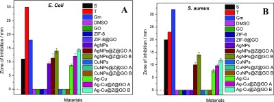
Zone of inhibition against (A) E. coli and (B) S. aureus.
3. Conclusions
In summary, ZIF-8@GO nanocomposites were successfully synthesized through a growth deposition method. Metal nanoparticles were successfully grown within the cavities of the ZIF-8 material as observed from TEM micrographs and confirmed through other techniques. The deposition of ZIF-8 prevented stacking of GO sheets, which also minimized aggregation of metal NPs. Ag@ZIF8@GO and Ag–Cu@ZIF-8@GO nanocomposites showed remarkable antibacterial activity toward both Gram-negative and Gram-positive bacteria when using the disc diffusion method. Given the outstanding antibacterial activity of Ag@ZIF8@GO and Ag–Cu@ZIF-8@GO composites and the fact that the composites can be easily synthesized and recovered after use, it is envisaged that these novel composites could offer promising opportunities in antibacterial applications in various fields in the future.
4. Experimental Section
4.1. Materials
Graphite powder for the production of GO, sodium nitrate (NaNO3), sulfuric acid (H2SO4, 98.0%), potassium permanganate (K2MnO4), hydrogen peroxide (H2O2, containing inhibitor, 30.0 wt % H2O), hydrochloric acid (HCl ≥32.0%), Zn(NO3)2·6H2O, absolute ethanol (99.0%), 2-methylimidazole, trimethylamine (TEA, ≥99.5), silver nitrate (AgNO3), copper(II) sulphate (CuSO4), and sodium borohydride (NaBH4), were all purchased from Sigma-Aldrich (South Africa) and were used as received without further purification processes. Deionized (DI) water was utilized for washing where fundamental.
4.2. Preparation of Graphene Oxide, ZIF-8, and ZIF-8@GO Composites
GO was synthesized using the modified Hummers method based on the reported procedure.19,25 In a typical experiment, graphite powder (1.0 g) was suspended in a NaNO3 (0.5 g) solution of concentrated H2SO4 (23 mL) in an ice bath and further stirred for 1 h at that temperature. K2MnO4 (3.0 g) was slowly added to this suspension to maintain the temperature below 20 °C as this was an exothermic reaction. The temperature of the mixture was subsequently raised to 35 °C and stirred for a further 24 h. The suspension was allowed to equilibrate to room temperature (ca. 25 °C) and then DI water (500 mL) was added under vigorous stirring at room temperature. This was followed by the addition of H2O2 (30% in water, 5.0 mL) and left to stir for a further 30 min. The suspension was filtered and subsequently washed with HCl, followed by DI water. The resultant graphite oxide was exfoliated into GO sheets by ultrasonication in N-methyl-2-pyrrolidinone in an ice bath for 1 h.
Pristine ZIF-8 nanoparticles were synthesized at room temperature following the literature method with slight modifications (Figure 16A).24,37 An aqueous solution (25 mL) of TEA (2.0 g, 19.8 mmol) and 2-methylimidazol (3.24 g, 39.5 mmol) was added into an aqueous solution (25 mL) of Zn(NO3)2·6H2O (0.1833 g, 0.616 mmol) under vigorous stirring. Stirring was stopped after 1 h and the formed ZIF-8 crystals washed with DI water and recovered by centrifugation (7000 rpm, 10 min) 3 times. The powder was dried in an oven at 60 °C for 24 h.38,39
Figure 16.

(A) synthesis of ZIF-8, (B) in situ growth of ZIF-8@GO with the nanoparticles carried inside ZIF-8. Adapted with permission from ACS Sustainable Chem. Eng. 2017,5, 11204–11214. Copyright 2017 American Chemical Society.37
The ZIF-8@GO composite was prepared by in situ growth of ZIF-8 onto the GO via the same process used for ZIF-8. In short, GO powder (0.5 g) was added into a solution of Zn(NO3)2·6H2O and the suspension sonicated for 30 min. To this suspension was added aqueous solution (25 mL) of TEA (2.0 g, 19.8 mmol) and 2-methylimidazol (3.24 g, 39.5 mmol) under vigorously stirring. A schematic representation of the method is shown in Figure 16B.
4.3. Synthesis of Antibacterial Agents: Ag@ZIF-8@GO, Cu@ZIF-8@GO, Ag–Cu@ZIF-8@GO
Ag and Cu nanoparticles were prepared by reducing AgNO3 and CuSO4 with NaBH4 in a light-proof reaction vessel to prevent light-induced reactions of Ag owing to its photosensitivity. Typically, AgNO3 (0.5 g, 2.94 mmol) was added into 25 mL DI water and sonicated for 2 min to ensure complete dissolution of AgNO3. Thereafter, aqueous NaBH4 solution (50 mL 0.5 mol L–1) was added dropwise while stirring at room temperature in the dark for 1 h to induce complete reduction. After 24 h of ageing in the dark, the mixture was centrifuged and washed with absolute ethanol (50 mL) and DI water (50 mL) sequentially. The AgNPs were obtained after drying in a vacuum oven for 6 h. CuNPs was synthesized by following the same procedure. Similarly, CuSO4 (0.5 g, 3.13 mmol) was used to synthesize CuNPs. The nanoparticles@ZIF-8@GO were incorporated through a simple impregnation method followed by the reduction of metals (Ag+ and Cu2+). The ZIF-8@GO (0.5 g) composite was sonicated in 25 mL of DI water for 2 min; after sonication, the metal precursors (AgNO3, CuSO4, or simultaneously AgNO3 and CuSO4) were added and the same procedure was followed as prescribed above. The resulting structure of the composite is illustrated in Figure 16B.
4.4. Characterization of GO, ZIF-8, and ZIF-8@GO Nanoparticles as Well as Ag@ZIF-8@GO, Cu@ZIF-8@GO, and Ag–Cu@ZIF-8@GO Nanocomposites
The morphology of the samples was analyzed using the scanning electron microscope TESCAN VEGA 3 with the acceleration voltage of 20 kV as well as the TEM JOEL JEM-2100 electron microscope (acceleration voltage of 200 kV). FTIR spectra of the samples were obtained using a PerkinElmer Spectrum 100 FTIR spectrometer. The samples were analyzed over a range of 650–4000 cm–1 with a resolution of 4 cm–1. All spectra were averaged over 16 scans. p-XRD was used to determine the crystalline structures of the materials. A D8 ADVANCE diffractometer (X’Pert, Germany) with PSD Vantec-1 detectors and Cu Kα radiation (λ = 1.5406), a tube voltage of 40 kV, a current of 40 mA, and a V20 slit were utilized. The samples were scanned in the locked couple mode with 2θ increment in 0.5 s steps. The BET (Micrometrics ASAP 2020) was used to test the surface area of solids at 150 °C. XPS (Axis Supra) was used to analyze the elemental composition and state of the materials.
4.5. Antibacterial Activity Measurements
The sensitivity of the microorganisms to nanocomposites (Ag–Cu@ZIF-8@GO) was tested by using the disc diffusion method described by Pokhrel et al. and Bauer et al.22,23 All pathogenic strains (Gram-negative strains: E. coli ATCC25922; Gram-positive: S. aureus ATCC25923 purchased from Davies diagnostics South Africa) were grown overnight at 37 °C in Muller–Hinton broth and adjusted using 0.5 McFarland standards such that the concentration was 107 to 108 colony forming unit (CFU/mL). Under sterile conditions, E. coli and S. aureus strains were suspended in saline solution and 0.10 mL of each pathogenic strain was spread on Muller–Hinton agar. Sterile circular filter paper discs with a diameter of 6 mm were used as a support for the nanocomposites. The nanocomposites (0.2 mg) were suspended in 10% DMSO (2.0 mL) from which 0.01 mL was deposited onto the paper discs. The loaded filter paper discs were mounted on Petri dishes containing the pathogenic strains. Streptomycin, gentamicin, and tetracycline (Mast Diagnostics, U.K. 243981) were used as the positive control and mounted on the Petri dishes as described above for the composites. DMSO (10%) was used the negative control. Three to four discs of different nanocomposites were placed on each plate inoculated with E. coli or S. aureus pathogenic strains and incubated at 37 °C for 24 h. Antimicrobial activity was observed after 24 h by measuring the zone of inhibition (in mm) as shown in Figure 17. The antibacterial tests were performed in triplicates.
Figure 17.

Illustration of measuring the zone of inhibition.
Acknowledgments
The authors acknowledge the Department of Science and Innovation through the DSI/MINTEK Nanotechnology Innovation Centre (NIC) as well as DST/NRF SA-Ghana Flagship grant (no. 114688) for providing financial support during the course of the project.
The authors declare no competing financial interest.
References
- Clardy J.; Fischbach M. A.; Currie C. R. The natural history of antibiotics. Curr. Biol. 2009, 11, R437–R441. 10.1016/j.cub.2009.04.001. [DOI] [PMC free article] [PubMed] [Google Scholar]
- Mahmoodi S.; Elmi A.; Hallaj-nezhadi S. Copper nanoparticles as antibacterial agents. J. Mol. Pharm. Org. Process Res. 2018, 06, 140. 10.4172/2329-9053.1000140. [DOI] [Google Scholar]
- Zheng K.; Setyawati M. I.; Leong D. T.; Xie J. Antimicrobial silver nanomaterials. Coord. Chem. Rev. 2018, 357, 1–17. 10.1016/j.ccr.2017.11.019. [DOI] [Google Scholar]
- Jian W.; Ma Y.; Wu H.; Zhu X.; Wang J.; Xiong H.; Lin L.; Wu L. Fabrication of highly stable silver nanoparticles using polysaccharide-protein complexes from abalone viscera and antibacterial activity evaluation. Int. J. Biol. Macromol. 2019, 128, 839–847. 10.1016/j.ijbiomac.2019.01.197. [DOI] [PubMed] [Google Scholar]
- Franci G.; Falanga A.; Galdiero S.; Palomba L.; Rai M.; Morelli G.; Galdiero M. Silver nanoparticles as potential antibacterial agents. Molecules 2015, 20, 8856–8874. 10.3390/molecules20058856. [DOI] [PMC free article] [PubMed] [Google Scholar]
- Vélez E.; Campillo G.; Morales G.; Hincapié C.; Osorio J.; Arnache O. Silver nanoparticles obtained by aqueous or ethanolic aloe Vera extracts: An assessment of the antibacterial activity and mercury removal capability. J. Nanomater. 2018, 2018, 1–7. 10.1155/2018/7215210. [DOI] [Google Scholar]
- Fernando S. S. N.; Gunasekara T. D. C. P.; Holton J. Antimicrobial nanoparticles: applications and mechanisms of action. Sri Lankan J. Infect. Dis. 2018, 8, 2–11. 10.4038/sljid.v8i1.8167. [DOI] [Google Scholar]
- Sánchez-Sanhueza G.; Fuentes-Rodríguez D.; Bello-Toledo H. Copper nanoparticles as potential antimicrobial agent in disinfecting root canals. A systematic review. Int. J. Odontostomat. 2016, 3, 547–554. 10.4067/s0718-381x2016000300024. [DOI] [Google Scholar]
- Guo Y.-F.; Fang W.-J.; Fu J.-R.; Wu Y.; Zheng J.; Gao G.-Q.; Chen C.; Yan R.-W.; Huang S.-G.; Wang C.-C. Facile synthesis of Ag@ZIF-8 core-shell heterostructure nanowires for improved antibacterial activities. Appl. Surf. Sci. 2018, 435, 149–155. 10.1016/j.apsusc.2017.11.096. [DOI] [Google Scholar]
- Zhang H.-Z.; Zhang C.; Zeng G.-M.; Gong J.-L.; Ou X.-M.; Huan S.-Y. Easily separated silver nanoparticle-decorated magnetic graphene oxide: synthesis and high antibacterial activity. J. Colloid Interface Sci. 2016, 471, 94–102. 10.1016/j.jcis.2016.03.015. [DOI] [PubMed] [Google Scholar]
- Perdikaki A.; Galeou A.; Pilatos G.; Karatasios I.; Kanellopoulos N. K.; Prombona A.; Karanikolos G. N. Ag and Cu monometallic and Ag/Cu bimetallic nanoparticle–graphene composites with enhanced antibacterial performance. ACS Appl. Mater. Interfaces 2016, 8, 27498–27510. 10.1021/acsami.6b08403. [DOI] [PubMed] [Google Scholar]
- Song B.; Zhang C.; Zeng G.; Gong J.; Chang Y.; Jiang Y. Antibacterial properties and mechanism of graphene oxide-silver nanocomposites as bactericidal agents for water disinfection. Arch. Biochem. Biophys. 2016, 604, 167–176. 10.1016/j.abb.2016.04.018. [DOI] [PubMed] [Google Scholar]
- Shao W.; Liu X.; Min H.; Dong G.; Feng Q.; Zuo S. Preparation, characterization, and antibacterial activity of silver nanoparticle-decorated graphene oxide nanocomposite. ACS Appl. Mater. Interfaces 2015, 7, 6966–6973. 10.1021/acsami.5b00937. [DOI] [PubMed] [Google Scholar]
- Govarthanan M.; Thangasamy S.; Koildhasan M.; Radhika R.; Shanthi K.; Lee K. J.; Cho M.; Seralathan K.-K.; Byung-Taek O. Biosynthesis and characterization of silver nanoparticles using panchakavya, an Indian traditional farming formulating agent. Int. J. Nanomed. 2014, 9, 1593–1599. 10.2147/ijn.s58932. [DOI] [PMC free article] [PubMed] [Google Scholar]
- Huang L.; Yang H.; Zhang Y.; Xiao W. Study on synthesis and antibacterial properties of Ag NPs/GO nanocomposites. J. Nanomater. 2016, 2016, 5685967. 10.1155/2016/5685967. [DOI] [Google Scholar]
- Liu L.; Zhou X.; Yan Y.; Zhou J.; Zhang W.; Tai X. Bimetallic gold-silver nanoparticles supported on Zeolitic Imidazolate Framework-8 as highly active heterogenous catalysts for selective oxidation of Benzyl Alcohol into Benzaldehyde. Polymers 2018, 10, 1089–1104. 10.3390/polym10101089. [DOI] [PMC free article] [PubMed] [Google Scholar]
- Jafari S.; Ghorbani-Shahna F.; Bahrami A.; Kazemian H. Effects of post-synthesis activation and relative humidity on adsorption performance of ZIF-8 for capturing toluene from a gas phase in a continuous mode. Appl. Sci. 2018, 8, 310–325. 10.3390/app8020310. [DOI] [Google Scholar]
- Jian M.; Liu B.; Liu R.; Qu J.; Wang H.; Zhang X. Water-based synthesis of zeolitic imidazolate framework-8 with high morphology level at room temperature. RSC Adv. 2015, 5, 48433–48441. 10.1039/c5ra04033g. [DOI] [Google Scholar]
- Makhetha T. A.; Moutloali R. M. Antifouling properties of Cu(tpa)@GO/PES composite membranes and selective dye rejection. J. Membr. Sci. 2018, 554, 195–210. 10.1016/j.memsci.2018.03.003. [DOI] [Google Scholar]
- Jian M.; Liu B.; Zhang G.; Liu R.; Zhang X. Adsorptive removal of arsenic from aqueous solution by zeolitic imidazolate framework-8 (ZIF-8) nanoparticles. Colloids Surf., A 2015, 465, 67–76. 10.1016/j.colsurfa.2014.10.023. [DOI] [Google Scholar]
- Modi A.; Verma S. K.; Bellare J. Hydrophilic ZIF-8 decorated GO nanosheets improve biocompatibility and separation performance of polyethersulfone hollow fiber membranes: A potential membrane material for bioartificial liver application. Mater. Sci. Eng., C 2018, 91, 524–540. 10.1016/j.msec.2018.05.051. [DOI] [PubMed] [Google Scholar]
- Kaur H.; Mohanta G. C.; Gupta V.; Kukkar D.; Tyagi S. Synthesis and characterization of ZIF-8 nanoparticles for controlled release of 6-mercaptopurine drug. J. Drug Deliv. Sci. Technol. 2017, 41, 106–112. 10.1016/j.jddst.2017.07.004. [DOI] [Google Scholar]
- Dong L.; Chen M.; Li J.; Shi D.; Dong W.; Li X.; Bai Y. Metal-organic framework-graphene oxide composites: A facile method to highly improve the CO2 separation performance of mixed matrix membranes. J. Membr. Sci. 2016, 520, 801–811. 10.1016/j.memsci.2016.08.043. [DOI] [Google Scholar]
- Shahriary L.; Athawale A. A. Graphene oxide synthesized by using modified hummers approach. Renew. Energy Environ. Eng. 2014, 2, 58–63. [Google Scholar]
- Wang J.; Wang Y.; Zhang Y.; Uliana A.; Zhu J.; Liu J.; Van der Bruggen B. Zeolitic imidazolate framework/graphene oxide hybrid nanosheets functionalized thin film nanocomposite membrane for enhanced antimicrobial performance. ACS Appl. Mater. Interfaces 2016, 8, 25508–25519. 10.1021/acsami.6b06992. [DOI] [PubMed] [Google Scholar]
- Delsante S.; Borzone G.; Novakovic R.; Piazza D.; Pigozzi G.; Janczak-Rusch J.; Pilloni M.; Ennas G. Synthesis and thermodynamics of Ag-Cu nanoparticles. Phys. Chem. Chem. Phys. 2015, 17, 28387–28393. 10.1039/c5cp02058a. [DOI] [PubMed] [Google Scholar]
- Huaman J. L. C.; Sato K.; Kurita S.; Matsumoto T.; Jeyadevan B. Copper nanoparticles synthesized by hydroxyl ion assisted alcohol reduction for conducting ink. J. Mater. Chem. 2011, 21, 7062–7069. 10.1039/c0jm04470a. [DOI] [Google Scholar]
- Zhang L.; Hu Y. H. Strong effects of higher-valent cations on the structure of the zeolitic Zn (2-methylimidazole) 2 framework (ZIF-8). J. Phys. Chem. C 2011, 115, 7967–7971. 10.1021/jp200699n. [DOI] [Google Scholar]
- Schejn A.; Aboulaich A.; Balan L.; Falk V.; Lalevée J.; Medjahdi G.; Aranda L.; Mozet K.; Schneider R. Cu2+-doped zeolitic imidazolate frameworks (ZIF-8): efficient and stable catalysts for cycloadditions and condensation reactions. Catal. Sci. Technol. 2015, 5, 1829–1839. 10.1039/c4cy01505c. [DOI] [Google Scholar]
- Schejn A.; Balan L.; Falk V.; Aranda L.; Medjahdi G.; Schneider R. Controlling ZIF-8 nano-and microcrystal formation and reactivity through zinc salt variations. CrystEngComm 2014, 16, 4493–4500. 10.1039/c3ce42485e. [DOI] [Google Scholar]
- Zhang Z.; Zhang X.; Xin Z.; Deng M.; Wen Y.; Song Y. Synthesis of monodisperse silver nanoparticles for ink-jet printed flexible electronics. Nanotechnology 2011, 22, 425601–425608. 10.1088/0957-4484/22/42/425601. [DOI] [PubMed] [Google Scholar]
- Ramasami A. K.; Ravishankar T. N.; Nagaraju G.; Ramakrishnappa T.; Teixeira S. R.; Balakrishna R. G. Gel-combustion-synthesized ZnO nanoparticles for visible light-assisted photocatalytic hydrogen generation. Bull. Mater. Sci. 2017, 40, 345–354. 10.1007/s12034-017-1372-6. [DOI] [Google Scholar]
- Xu D.; Fan D.; Shen W. Catalyst-free direct vapor-phase growth of Zn 1– x Cu x O micro-cross structures and their optical properties. Nanoscale Res. Lett. 2013, 8, 46–55. 10.1186/1556-276x-8-46. [DOI] [PMC free article] [PubMed] [Google Scholar]
- Cui S.-F.; Peng L.-P.; Zhang H.-Z.; Rasheed S.; Vijaya Kumar K.; Zhou C.-H. Novel hybrids of metronidazole and quinolones: synthesis, bioactive evaluation, cytotoxicity, preliminary antimicrobial mechanism and effect of metal ions on their transportation by human serum albumin. Eur. J. Med. Chem. 2014, 86, 318–334. 10.1016/j.ejmech.2014.08.063. [DOI] [PubMed] [Google Scholar]
- Quirós J.; Boltes K.; Aguado S.; de Villoria R. G.; Vilatela J. J.; Rosal R. Antimicrobial Metal–Organic Frameworks incorporated into electrospun fibers. Chem. Eng. J. 2015, 262, 189–197. 10.1016/j.cej.2014.09.104. [DOI] [Google Scholar]
- Yan X.; He B.; Liu L.; Qu G.; Shi J.; Hu L.; Jiang G. Antibacterial mechanism of silver nanoparticles in Pseudomonas aeruginosa: proteomics approach. Metallomics 2018, 10, 557–564. 10.1039/c7mt00328e. [DOI] [PubMed] [Google Scholar]
- Gong X.; Wang Y.; Kuang T. ZIF-8-based membranes for carbon dioxide capture and separation. ACS Sustain. Chem. Eng. 2017, 5, 11204–11214. 10.1021/acssuschemeng.7b03613. [DOI] [Google Scholar]
- Pokhrel H.; Baishya S.; Phukan B.; Pillai D.; Ashraf Rather M. Occurrence and distribution of multiple antibiotic resistance bacteria of public health significance in backwaters and aquaculture farm. Int. J. Curr. Microbiol. Appl. Sci. 2018, 7, 975–987. 10.20546/ijcmas.2018.702.121. [DOI] [Google Scholar]
- Bauer A. W.; Kirby W. M. M.; Sherris J. C.; Turck M. Antibiotic susceptibility testing by a standardized single disc method. Am. J. Clin. Pathol. 1966, 45, 493–496. 10.1093/ajcp/45.4_ts.493. [DOI] [PubMed] [Google Scholar]