Abstract
Intracellular diffusion underlies vital cellular processes. However, it remains difficult to elucidate how an unbound protein diffuses inside the cell with good spatial resolution and sensitivity. Here we introduce single-molecule displacement/diffusivity mapping (SMdM), a super-resolution strategy that enables the nanoscale mapping of intracellular diffusivity through local statistics of the instantaneous displacements of freely diffusing single molecules. We thus show that the diffusion of an average-sized protein in the mammalian cytoplasm and nucleus to both be spatially heterogeneous at the nanoscale, and such variations in local diffusivity correlate with the ultrastructure of the actin cytoskeleton and the chromosome, respectively. SMdM of differently charged proteins further unveils that the possession of positive, but not negative, net charges drastically impedes diffusion, and that the exact degree of slowdown is determined by the specific subcellular environments. We thus open a new door to probing intracellular properties and functions at the nanoscale.
The magic of life occurs when the right molecules meet. Whereas active transport provides an organized, yet costly means to move things around inside the eukaryotic cell, passive diffusion offers a mechanism for molecules to mix “for free”. It, however, remains difficult to map out how an average-sized protein diffuses in the live cell with good spatial resolution and sensitivity. Does intracellular diffusivity contain structures at the nanoscale, and if so, how are they modulated by the local intracellular structures and microenvironments, as well as by the properties of the diffuser itself?
Although environment-sensitive fluorescent probes have been developed to visualize related intracellular parameters and processes as viscosity, macromolecular crowding, and protein-folding dynamics1–6, they do not directly address diffusivity. Photobleaching and photoactivation-based techniques7,8 enable single-location diffusion measurements but are unamicable to spatial mapping. Fluorescence correlation spectroscopy (FCS) and related methods9–12 infer diffusivity from spatiotemporal fluctuations in intensity, but are sensitive to experimental conditions10,13 and achieve limited resolution and sensitivity in live cells. Recent advances in STED-FCS offer new opportunities for high spatiotemporal resolutions, but are often limited to membrane-bound molecules and typically do not provide two-dimensional (2D) maps of local diffusivity14,15.
Single-molecule tracking (SMT) has been highly successful for membrane- and chromosome-bound molecules and for molecules diffusing inside the small volumes of bacteria16–21. However, it remains challenging to apply SMT to unbound molecules freely diffusing inside the eukaryotic cell. For an average-sized protein with an intracellular diffusion coefficient D of7,22 ~20–30 μm2/s, the ~10 ms frame time in typical wide-field single-molecule experiments results in ~700 nm of diffusion in each dimension, hence severe motion-blur. Although stroboscopic illumination overcomes motion-blur23,24, tracking between frames remains difficult for the eukaryotic cell: with ~700 nm axial displacement, a molecule initially in focus readily diffuses out of the focal range (~±400 nm for a high-NA objective) in the subsequent frame (see below).
We here develop a strategy to first determine the nanoscale displacements of freely diffusing single molecules in short (~1 ms) time windows through the application of a pair of closely timed excitation pulses. By repeating such pulse pairs for ~104 times and locally accumulating the resultant single-molecule displacements, we next construct super-resolution maps of diffusion rate, and hence uncover nanoscale diffusivity heterogeneities in live mammalian cells. We name this strategy single-molecule displacement/diffusivity mapping (SMdM), echoing the concept of single-molecule localization microscopy (SMLM), which generates super-resolution images by accumulating single-molecule localizations25–27.
Results
SMdM evaluates the instantaneous displacements of freely diffusing single molecules.
We started by expressing free mEos3.2, a photoswitchable, monomeric fluorescent protein (FP) commonly used in SMLM28, in the cytoplasm of mammalian cells. Along with a short cloning-site sequence, the expressed protein (mEos3.2-C1; Supplementary Table 1) contained 252 amino acids (AA) (~28 kDa), close to the medium size of human proteins (248 AA by abundance22). As with typical SMLM experiments, we illuminated several micrometers into the coverslip-adhered live cells with a 561 nm excitation laser, and used a weak 405 nm laser to photoswitch a small fraction of the expressed mEos3.2 molecules to the 561 nm-excitable, “red” state, hence a means to control the amount of fluorescent single molecules in the view16,26. As expected, at a typical 109 Hz framerate (camera frame time T = 9.16 ms), freely diffusing single mEos3.2 molecules appeared blurry (Fig. 1a). The application of stroboscopic illumination23,24, in which excitation pulses τ = 500 μs in duration were synchronized to the center of each camera frame, provided clear single-molecule images (Fig. 1b). However, in the succeeding frame, after the frame time of T = 9.16 ms, molecules detected in the first frame already diffused out of the focal range and so could not be tracked (Fig. 1b).
Fig. 1 |. SMdM for single mEos3.2 FP molecules freely diffusing in the cytoplasm of live mammalian cells.
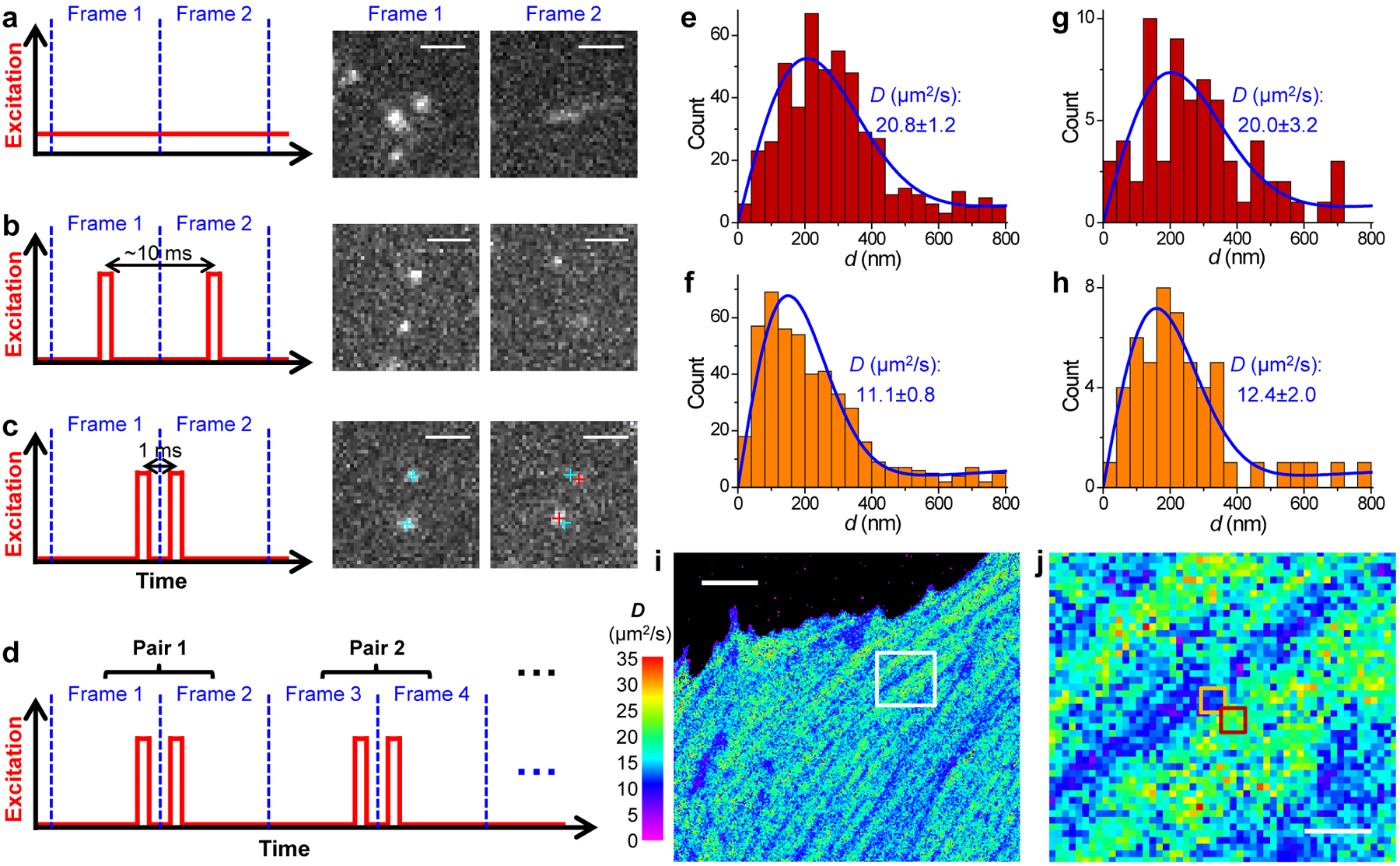
(a) Conventional imaging with continuous laser illumination and a recording framerate of 109 Hz. (b) Stroboscopic illumination, with excitation pulses τ = 500 μs in duration synchronized to the center of each camera frame. (c) Placing two excitation pulses towards the end of the first frame and the beginning of the second frame, respectively, so that the center-to-center time separation between the two recorded images is reduced to 1 ms. Cyan and red crosses mark the super-localized positions of two detected molecules in Frame 1 and Frame 2, respectively. (d) Such paired frames are repeated ~104 times to enable statistics. (e,f) Distribution of the 1-ms single-molecule displacement d for two adjacent 300×300 nm2 areas [red and orange boxes in (j)]. (g,h) Distribution of d for two 100×100 nm2 areas at the centers of (e,f), respectively. Blue curves in (e-h) give MLE results using eqn. 2 in Methods, with resultant diffusion coefficient D and uncertainty σ labeled in each panel. (i,j) Map of intracellular diffusivity constructed through MLE of the d distribution in every 100×100 nm2 spatial bin. (j) is a zoom-in of the white box in (i). Scale bars: 2 μm (a-c), 5 μm (i), 1 μm (j). (i) and (j) were independently repeated 11 times with similar results.
To overcome this issue, we reduced the temporal separation between the pair of captured images by placing two excitation pulses towards the end of the first frame and the beginning of the second frame, respectively (Fig. 1c). Thus, at a Δt = 1 ms center-to-center separation between the two pulses, molecules being detected in the first frame (due to the first pulse) had only traveled moderately (to stay within focus) at the time of the second pulse (captured in the second frame) (Fig. 1c). Comparing the super-localized positions of the molecules in the two frames thus yielded their nanoscale displacements (d) in the Δt = 1 ms time window.
We next repeated ~104 of the above paired frames to enable statistics (Fig. 1d). The temporal proximity of the paired excitation pulses (Δt) left ample time between the unpaired pulses (2T−Δt) for different molecules to diffuse into the focal range as independent reporters of local diffusivity. The resultant, accumulated d values were spatially binned to evaluate local D. Fig. 1e–h show statistics for two spots ~400 nm apart (Fig. 1j below), for bins 300×300 nm2 (Fig. 1ef) and 100×100 nm2 (Fig. 1gh) in size, respectively, that exhibited notably different local distributions. Fitting the distributions using a modified 2D random-walk model (Methods) through maximum likelihood estimation (MLE) yielded D with reasonable uncertainties for both bin sizes (Fig. 1e–h). We further demonstrated the robustness of the model for high single-molecule densities (Extended Data Fig. 1 and Fig. 6 below). Color-plotting the D values from MLE of each 100×100 nm2 spatial bin thus rendered a super-resolution map of local D across the full view (Fig. 1i,j).
Fig. 6 |. SMdM of the non-photoswitchable GFP mEmerald in the mammalian cytoplasm.
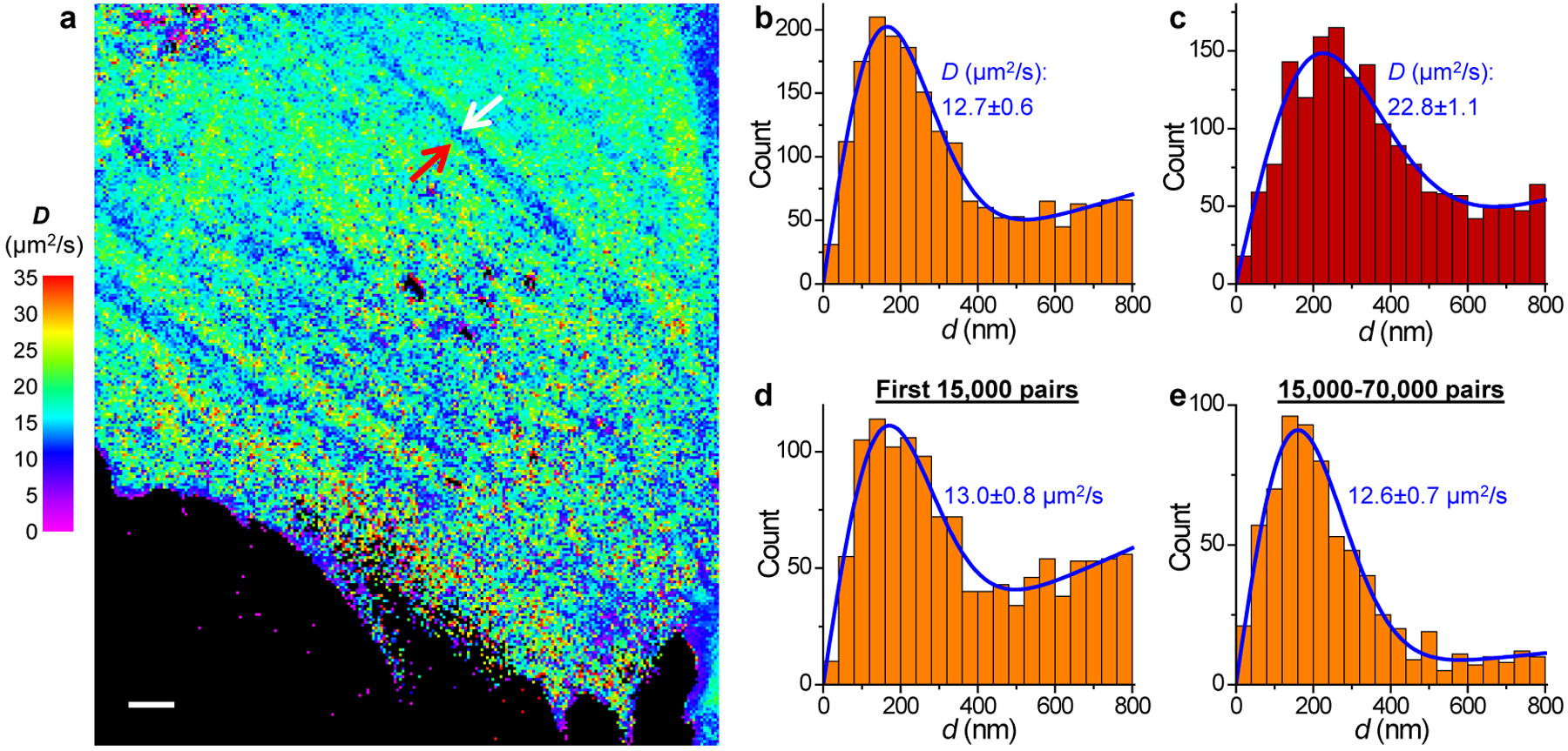
(a) SMdM diffusivity map of unbound mEmerald in the cytoplasm of a live PtK2 cell. The experiment was independently repeated 11 times with similar results. (b,c) Distribution of the 1-ms single-molecule displacement for two 360×360 nm2 areas inside (b; white arrow in a) and outside (c; red arrow in a) a linear structure of reduced local diffusivity. (d,e) Distribution of single-molecule displacement for the same area as b, collected in the first 15,000 pairs of frames (d; ~0.4 molecules/μm2/frame) and in the 15,000–70,000 pairs of frames (e; ~0.06 molecules/μm2/frame), respectively. Blue lines in b-e: MLE results using eqn. 2, with resultant D and uncertainty σ labeled. Scale bar in a: 2 μm.
Correlative SMdM-SMLM identifies nanoscale diffusivity heterogeneity and anisotropy due to the actin cytoskeleton.
For mEos3.2 molecules freely diffusing in the cytoplasm of live mammalian cells, SMdM showed typical D of 20–25 μm2/s for the high-D regions (Figs. 2a,c and Extended Data Figs. 1 and 2), comparable to previous, spatially unresolved results on FPs7,22. Treating the cells with a 2× hyperosmotic medium led to substantially reduced D down to ~8 μm2/s for the high-D regions (Fig. 2b), consistent with increased macromolecular crowding owning to water loss5,29.
Fig. 2 |. SMdM of free mEos3.2 in the mammalian cytoplasm and correlated SMLM of the actin cytoskeleton.
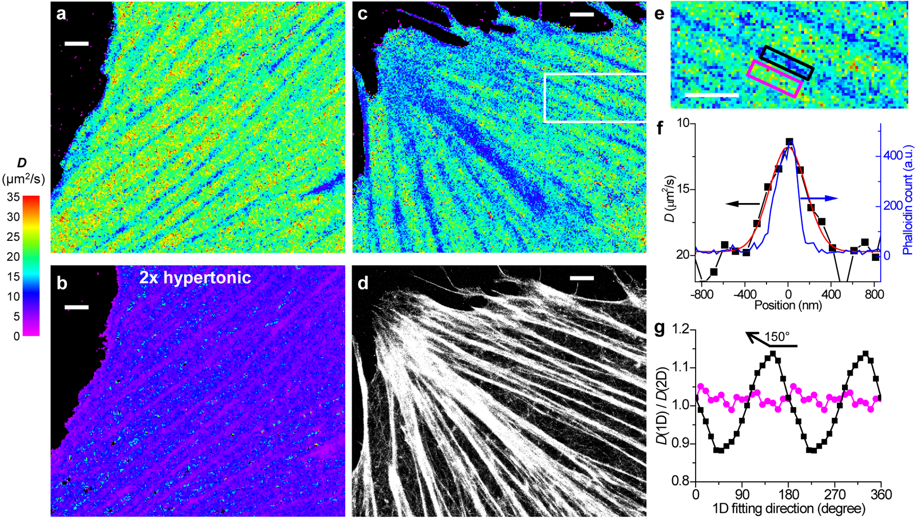
(a) SMdM diffusivity map of mEos3.2-C1 in the cytoplasm of a live PtK2 cell. (b) The same cell in a 2× hyperosmotic medium. (a) and (b) were independently repeated 3 times with similar results. (c,d) Correlated SMdM diffusivity map of mEos3.2 in another live PtK2 cell (c), vs. SMLM image of Alexa Fluor 647 phalloidin-labeled actin in the fixed cell (d). (e) Zoom-in of the white box in c. (c), (d) and (e) were independently repeated 5 times with similar results. (f) Variations in the SMdM-measured D value (black squares on a flipped y-axis; red line: Gaussian fit with an FWHM of 400 nm) and the SMLM-detected phalloidin density (blue curve; FWHM is 230 nm; see y-axis on the right) across the black-boxed region in e. (g) Ratio of the D values obtained from the direction-dependent 1D diffusion models over that from the 2D isotropic model, for the black- and magenta-boxed regions in e, respectively. The D values from the 2D isotropic model are 12.4 and 21.8 μm2/s for the two regions, respectively. Scale bars: 2 μm (a-e).
Meanwhile, the spatial mapping capability of SMdM revealed substantial diffusivity heterogeneities at the nanoscale. For the flat, spread parts of cells, SMdM D maps often showed continuous, linear features where D reduced markedly down to ~10 μm2/s (Figs 1i, 2a,c, and Extended Data Fig. 2). As these linear structures are reminiscent of actin cytoskeleton bundles, we fixed the cells and achieved correlated SMLM for actin using a dye-tagged phalloidin stain30. Good correspondences were found between the SMdM-revealed low-D regions and the SMLM-visualized actin bundles (Figs. 2c,d, and Extended Data Fig. 2). Plotting the SMdM-measured D values across an actin bundle 230 nm in FWHM (full width at half maximum) gave an FWHM of 400 nm (Fig. 2ef).
To examine whether the linear diffusivity features induced by the actin bundles could be characterized by diffusivity anisotropy, we fitted the SMdM-accumulated single-molecule displacements to one-dimensional (1D) diffusion models in different directions (Methods). For the actin-bundle region, the direction-dependent 1D diffusion models yielded D values that oscillated around the D value from the isotropic 2D model (Fig. 2g), with a ~±14% difference achieved for the maximal and minimal values in directions along (e.g., ~150°) and perpendicular to the actin bundle, respectively. In comparison, for a region outside the actin bundle, the 1D diffusion models yielded little directional dependence, and the D values obtained were within a few percent of that obtained from the 2D model (Fig. 2g).
Correlative SMdM-SMLM of the nucleus unveils nanoscale diffusivity heterogeneity due to the nucleolus and the chromatin.
By setting the focal plane a few micrometers into the cell, we next performed SMdM at the central depth of the nucleus (Fig. 3a and Extended Data Fig. 3). D of ~20 μm2/s was thus found for the fastest regions of the nucleus (red arrows in Fig. 3a), consistent with the view that the nucleosol shares similar diffusion properties as the cytosol31. Meanwhile, micrometer-sized globule structures were noted, where the local D dropped substantially to ~6 μm2/s (asterisk in Fig. 3a). Bright-field transmission images indicated that they corresponded to the nucleoli (Extended Data Fig. 3), where a high crowdedness of proteins and nucleic acids is expected32.
Fig. 3 |. SMdM of free mEos3.2 in the nucleus, and correlated SMLM of DNA.
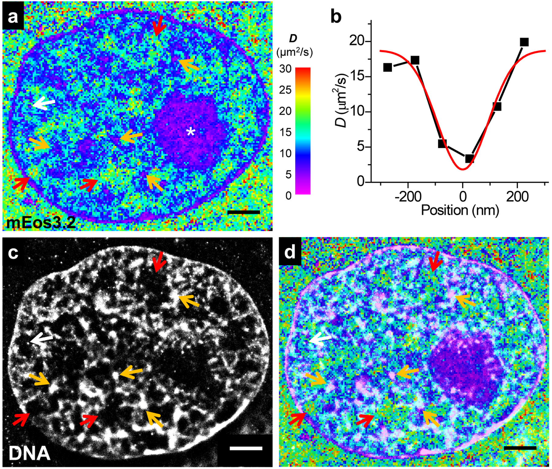
(a) SMdM diffusivity map of mEos3.2-C1 at the central depth of the nucleus of a live PtK2 cell. (b) Variation in the SMdM-determined D along the horizontal direction for a spot-like structure marked by the white arrow in a. Red line: Gaussian fit with an FWHM of 220 nm. (c) SMLM image of the fixed cell using the DNA stain NucSpot Live 650. (d) Overlay of (a) and (c). Scale bars: 2 μm. These experiments were independently repeated 23 times with similar results.
Close examination of the SMdM data further revealed semi-structured, fractal-like nanoscale features of lowered D (~10 μm2/s), which sporadically evolved into tight foci of very low D of <~5 μm2/s (orange arrows in Fig. 3a). White arrow points to one example in which SMdM resolved a diffusion slow-down region with an apparent FWHM of 220 nm (Fig. 3b). Correlated SMLM on the fixed cell using a DNA stain (Fig. 3c) showed that the highest D values were consistently observed for regions devoid of DNA (red arrows in Fig. 3acd), whereas the low D regions corresponded to DNA structures, with the slowest foci often corresponding to clusters of high local DNA density (orange and white arrows), a structure indicative of densely packed structures as the heterochromatin. See Extended Data Fig. 3 for additional examples: the spatial patterns of diffusivity correlated well with diverse chromatin ultrastructures.
For specific visualization of diffusion inside the nucleus, we further added a nuclear localization sequence (NLS)33 to mEos3.2 (Supplementary Table 1). Interestingly, although SMdM maps of mEos3.2-NLS again correlated well with the SMLM-resolved DNA, the actual D values dropped by one order of magnitude (Extended Data Fig. 4). As this big drop is unlikely due to the small size difference (262 vs. 252 AAs), we questioned what alternative factors could have dominated the diffusion behavior, and noticed the strong positive charge of NLS: Under the physiological pH of 7.4, the net charges of the mEos3.2-C1 and mEos3.2-NLS proteins were +2 and +15, respectively (Supplementary Table 1).
SMdM of differently charged mEos3.2 species unveils positive net charge as a key determinant of intracellular diffusivity.
To test the possible effect of protein charge on intracellular diffusion, we added short, consecutive Asp/Glu and Arg/Lys sequences to the C-terminus of mEos3.2, yielding net charges of −14, −7, 0, +7, and +14 for the expressed protein (Supplementary Table 1). SMdM revealed an interesting trend: For all subcellular environments, the two negatively charged (−14, −7) species (Fig. 4a,b) both yielded D comparable to that of the neutral species (Fig. 4c), but slightly higher than that of the original mEos3.2-C1 (+2 charges) (Figs. 2, 3, and 4f). For the +7 charged protein, however, a ~50% reduction in D was found across all subcellular environments (Fig. 4d,f). Meanwhile, extremely slow diffusion was found for the +14 charged protein (Fig. 4e): Curiously, as D dropped to ~0.5 μm2/s in the cytoplasm, higher values of up to ~3 μm2/s were retained in the nucleus, comparable to what we initially noticed for mEos3.2-NLS (+15 charges; Extended Data Fig. 4).
Fig. 4 |. SMdM of mEos3.2 species of different net charges.
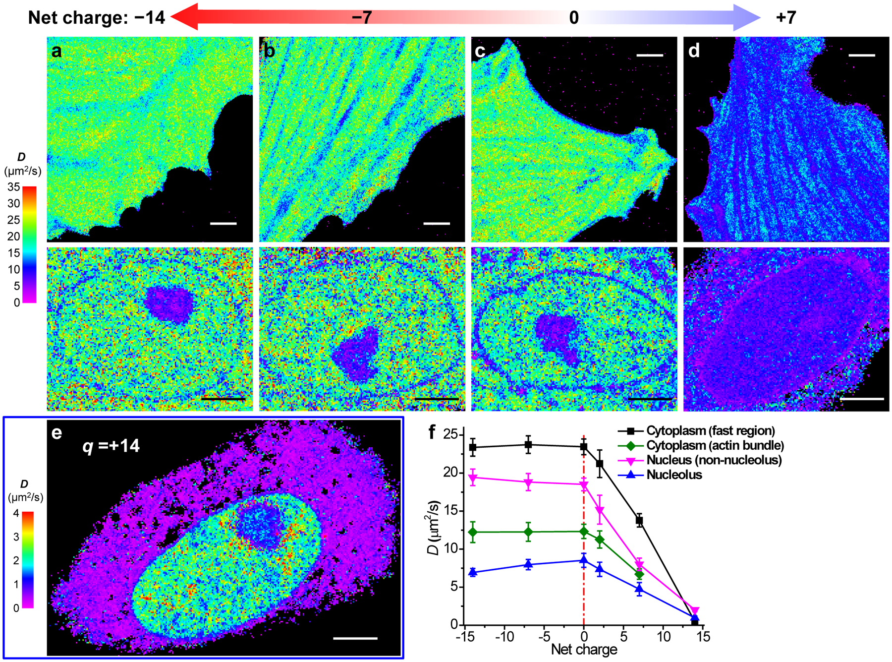
(a-d) SMdM diffusivity maps of mEos3.2 species of −14 (a), −7 (b), 0 (c), and +7 (d) net charges expressed in live PtK2 cells. The top and bottom panels show representative results in the spread parts of cells and the nuclei, respectively. The experiments were independently repeated 6, 8, 7 and 9 times for (a), (b), (c) and (d) in cytosol, and 21, 22, 7 and 13 times for (a), (b), (c) and (d) in nucleus, with similar results. (e) SMdM diffusivity map of +14 charged mEos3.2 in a live PtK2 cell, on a substantially reduced D scale. The experiment was independently repeated 15 times with similar results. (f) Mean D values for the above proteins in different subcellular environments. For cytoplasm, averaged D is presented for fast regions with no apparent slowdown due to the actin cytoskeleton (black; n = 9 cells for +7 charge and n = 6 cells for the other charges), as well as for the actin-bundle regions (green; n = 6, 6, 7, 6, 9 cells for charges of −14, −7, 0, +2, +7, respectively). The nucleus data are simply divided into nucleolus (blue; n = 7, 7, 6, 10, 12, 6 cells for charges of −14, −7, 0, +2, +7, +14, respectively) and non-nucleolus (magenta; n = 7, 7, 7, 10, 13, 6 cells for charges of −14, −7, 0, +2, +7, +14, respectively) regions. Error bars: standard deviations between individual cells (n > 6 cells for each data point). Scale bars: 4 μm (a-e).
To elucidate whether the above diffusion slowdown was due to consecutive Arg/Lys sequences, which might bind to importins33 or DNA34, we further performed SMdM for two other +7 charged proteins, one containing 7 sparsely distributed Arg/Lys in a 21 AA sequence (+7B; Supplementary Table 1), and another with modifications to the mEos3.2 sequence at 3 well-separated locations (+7C; Supplementary Table 1). Similar degrees of diffusion slowdown (vs. the neutral protein, Figs. 4c and 5a) were found for both proteins (Fig. 5c,d) when compared to the original one with consecutive Arg/Lys (+7A; Figs. 4d and 5b), with similar trends observed across different subcellular environments (Fig. 5e). This result indicates that it was the effect of net charge, rather than specific sequences, that drove the different diffusion behaviors.
Fig. 5 |. SMdM of different +7 charged species.
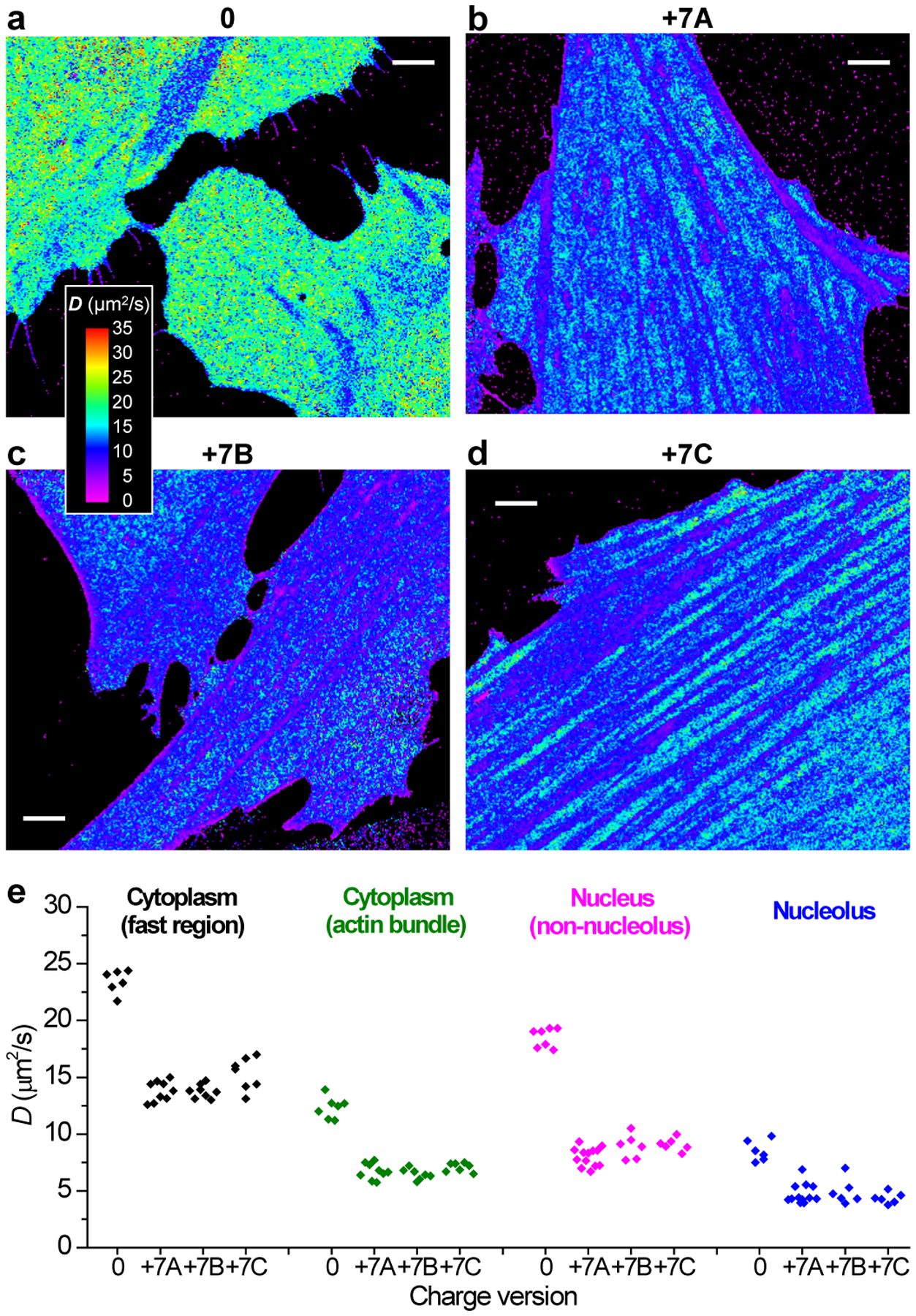
(a) Another example of SMdM diffusivity map of 0-charged mEos3.2 in the cytoplasm of live PtK2 cells. (b-d) Representative SMdM diffusivity maps for three different versions of +7 charged FPs in the cytoplasm of live PtK2 cells. (b) +7A: consecutive Arg/Lys at the C-terminus of mEos3.2. (c) +7B: 7 Arg/Lys distributed over 21 AAs at the C-terminus of mEos3.2. (d) +7C: modifications to the mEos3.2 sequence at 3 well-separated locations. The experiments were independently repeated 7, 9, 8 and 15 times for (a), (b), (c) and (d) with similar results. (e) Comparison of the mean D values for the above proteins in different subcellular environments. Points: results from individual cells. Scale bars: 4 μm (a-d).
SMdM is applicable to conventional, non-photoactivatable fluorophores.
Whereas our results above have focused on the photoactivated mEos3.2 FPs, we conclude by generalizing SMdM to non-photoactivated fluorophores. Using a single excitation laser, we first photobleached most of the fluorophores in the field of view, and then performed SMdM. As discussed earlier, the paired stroboscopic excitation scheme of SMdM left ample time (2T−Δt) for fluorophores to diffuse in and out of the imaging area in between the imaging periods (Δt). Consequently, we were able to accumulate many frames of single-molecule images through fluorophore exchange in lieu of photoactivation. Good SMdM results were thus obtained for the intracellular diffusion of the un-photoactivated “green” form of mEos3.2 (Extended Data Fig. 5), as well as the widely-used, non-photoactivatable GFP mEmerald (Fig. 6). Similar diffusivity behavior was observed for both cases when compared to our results above on the photoactivated “red” form of mEos3.2, including both the typical D values and linear features of diffusion slowdown regions (Fig. 6a). Single-molecule displacement distributions were well fitted to our model (Fig. 6bc). Notably, although the lack of photoactivation led to a drop in the single-molecule density over time, the fitting model was robust against this issue (Fig. 6de).
Discussion
By eliminating the need to track each molecule over consecutive frames but instead locally accumulating the instantaneous displacements of single molecules that stochastically entered the focal plane, SMdM successfully mapped out how unbound proteins diffuse in the eukaryotic cell at the super-resolution level. The application of a pair of closely-timed excitation pulses across tandem detection frames allowed access to single-molecule displacements down to 1 ms time windows in the wide-field, and by only detecting each molecule for two frames, relaxed the usual need for highly photostable fluorophores in SMT and FCS experiments12,18–20. The relatively long time lapse between the unpaired excitation pulses further facilitated the exchange of probes, so that non-photoactivatable fluorophores could be probed with high throughput inside the cell. The spatial binning of single-step displacements for fitting to background-tolerant diffusion models may also be generally useful for the construction of high-resolution diffusion maps.
For the cytoplasm, SMdM unveiled actin-related local diffusivity heterogeneity and anisotropy. Whereas photobleaching and FCS experiments with actin disrupting agents have suggested that, at the whole-cell level, the actin cytoskeleton impedes intracellular diffusion35,36, imaging with viscosity-sensing dyes detects no distinct intracellular structures1,4. In contrast, SMdM directly resolved local slowdown in D at the nanoscale and linked it to the SMLM-visualized actin ultrastructure. Fitting SMdM data to 1D diffusion models in different directions further unveiled diffusivity anisotropy, so that maximal and minimal D values were respectively observed along and perpendicular to the actin bundles. The moderate, up to ~±14% deviations of D values between the angle-dependent 1D and anisotropic 2D models for the actin-bundle region, together with the few-percent deviations for the non-bundle region, further suggest that our 2D diffusion analysis in a fixed plane (due to the lack of axial localization) should largely capture the diffusive behavior in three dimensions. Whereas most previous studies on intracellular diffusion are based on isotropic diffusion models7–12, in-plane diffusion anisotropy has been occasionally examined37. The possible extension of SMdM to diffusivity anisotropy in 3D awaits future incorporation of reliable 3D localization methods that are immune to single-molecule motion-blur.
For the nucleus, the high resolution and sensitivity of SMdM helped establish, at the nanoscale, a direct association between local D and the SMLM-resolved chromatin ultrastructure. Although single-location FCS measurements have previously shown chromatin- and nucleolus-related diffusion slowdown38, FCS mapping in ~1 μm-spaced arrays finds no correlation between D and chromatin structure39.
Following our mEos3.2-NLS results, SMdM next unveiled positive, but not negative, net charge as a key factor of intracellular diffusion slowdown, with the degree of slowdown dependent on the specific subcellular environment (Fig. 4f). In bacteria, a recent photobleaching-based study has reported substantial diffusion slowdown for positively charged GFP variants, a result ascribed to interaction with ribosomes40. The mammalian cell, however, is a much more complicated system. Notably, the mammalian cytosol contains a high concentration of small cations (~150 mM) but disproportionally low amounts of small anions (~15 mM)41. Charge balance thus mandates intracellular bio(macro)molecules to take the negative charges. Besides the negatively charged DNA and RNA backbones, we noticed that most proteins in the mammalian cytoplasm are either strongly negatively charged or neutral (Supplementary Table 2). Consequently, the SMdM-unveiled sign-asymmetric charge effects on diffusion may be rooted in the asymmetric distribution of intracellular charge: whereas a negatively charged diffuser is readily neutralized by the abundant small cations, a positively charged diffuser is dragged down by the negatively charged large biomolecules (Extended Data Fig. 6). Indeed, FCS has shown that in polymeric solutions, the diffusion of charged proteins is substantially impeded by opposite-charge, but not same-charge or neutral, polymers42.
From a methodological standpoint, our revelation of a strong dependence of D, and thus protein interactions, on positive net charges also calls for a reexamination of previous work in which FPs or other probes may have inadvertently shifted the protein net charge. Indeed, many common FPs are highly negatively charged (e.g., −7 or −8 charges for most GFP derivatives, including EGFP, ECFP, and Venus)43, and hence could bias experimental results towards the negative-charge regime, where the true effects of net charge are masked.
Together, SMdM has unveiled rich, nanoscale heterogeneities and charge effects in intracellular diffusivity. Whereas here SMdM has resolved diffusion features down to ~220 nm in FWHM, the ultimately achievable spatial, temporal, and diffusional resolutions depend on the actual system and await future experimental optimizations and theoretical analyses. The further integration of SMdM with other emerging super-resolution and single-molecule methods, e.g., spectrally resolved SMLM44,45, represents additional exciting possibilities.
Online Methods
Optical setup.
Single-molecule experiments were performed on a Nikon Ti-E inverted fluorescence microscope. Lasers at 488 nm (OBIS 488 LX, Coherent, 165 mW, for excitation of the non-photoactivatable GFP mEmerald and the un-photoactivated, “green” form of mEos3.2), 561 nm (OBIS 561 LS, Coherent, 165 mW, for excitation of the photoactivated, “red” form of mEos3.2) and 405 nm (Stradus 405, Vortran, 100 mW, for photoactivation of mEos3.2 to the “red” form) were collinearly combined and focused at the back focal plane of an oil-immersion objective lens (Nikon CFI Plan Apochromat λ 100×, NA 1.45) through a dichroic mirror (ZT488rdc-uf2 or ZT561rdc-uf2, Chroma, for the “green” and “red” channels, respectively). A translation stage shifted the laser beams toward the edge of the objective lens so that the light reached the sample at an incidence angle slightly smaller than the critical angle of the glass-water interface, thus illuminating a few micrometers into the sample. Fluorescence emission was filtered by a long-pass filter (ET500lp or ET575lp, Chroma, for the “green” and “red” channels, respectively) and an additional band-pass filter (ET535/70m or ET605/70m, Chroma, for the “green” and “red” channels, respectively) in front of the EMCCD camera (iXon Ultra 897, Andor). The excitation and photoactivation lasers were modulated by a multifunction I/O board (PCI-6733, National Instruments), which also read the camera exposure output TTL signal for synchronization.
Plasmid constructs.
The sequences of the FP constructs used in this study are listed in Supplementary Table 1. mEos3.2-C1 was a gift from Michael Davidson & Tao Xu (Addgene plasmid # 54550)28, and was used without modification as the “free” version of mEos3.2 (+2 net charge). mEos3.2-NLS was constructed by inserting the desired DNA sequence (Integrated DNA Technologies) between the SalI and BamHI restriction enzyme recognition sites within the short sequence at the C-terminus of mEos3.2-C1. mEOS3.2(+7B) was constructed by replacing the DNA strains after the Kpn2I restriction enzyme recognition site with the desired DNA sequence. Other mEos3.2-based versions were prepared by inserting the desired DNA sequences at the EcoRI restriction enzyme recognition site. The +7 charged mEosP5-C1(+7C) was constructed by replacing DNA strains in mEos3.2-C1 with the desired sequences between the AgeI and EcoRV restriction enzyme recognition sites and between the PflMI and Kpn2I restriction enzyme recognition sites. Free mEmerald (mEmerald-C1) was constructed by replacing the mEOS3.2 sequence of the mEOS3.2-C1 plasmid between the AgeI and BspEI restriction enzyme recognition sites with the mEmerald sequence. Verification of plasmid constructs was confirmed through Sanger sequencing. Net charges of the proteins were estimated by summing the charge of each amino acid or via the online tool Protein Calculator v3.4 (http://protcalc.sourceforge.net/), yielding comparable results (see details in the notes below Supplementary Table 1).
Cell culturing and transfection.
18-mm diameter glass coverslips were cleaned with a heated piranha solution (sulfuric acid and hydrogen peroxide at 3:1), and then rinsed with Milli-Q water (18.4 MΩ cm). Ptk2 and U2OS cells were cultured in Dulbecco’s Modified Eagle’s Medium (DMEM) with 10% fetal bovine serum (FBS), 1× GlutaMAX Supplement, and 1× non-essential amino acids (NEAA) in 5% CO2 at 37 °C. 24 hours before imaging, cells were transfected with the Neon Transfection System (ThermoFisher) according to the recommended protocol, and then plated onto the pre-cleaned glass coverslips at a density of ~40,000/cm2.
SMdM of live cells.
SMdM of live cells was performed in a Leibovitz’s L-15 medium containing 20 mM HEPES buffer, except for the hyperosmotic experiment, for which additional glucose was added at 49 mg/mL. For a typical recorded frame size of 256×256 pixels (~41×41 μm2 sample area), the EMCCD camera exposure time and dead time were 9.0 ms and 157 μs, respectively, hence camera frame time T = 9.16 ms, corresponding to a frame rate of 109.3 frames per second. To access sub-frame temporal resolution, for each paired frames, two excitation pulses of duration τ (500 μs typical) were placed towards the end of the first frame and the beginning of the second frame, respectively (Fig. 1c), at a center-to-center separation of Δt (1 ms typical, but 5 ms for the very slow diffusion in the NLS and +14 charged samples). The wait time between the two excitation pulses was evenly distributed across the EMCCD dead time. The estimated peak and average power densities of the excitation lasers at the sample were ~6 and 0.3 kW/cm2, respectively. For photoactivation of mEos3.2 to the “red” form, a low level of 405 nm laser was applied during the first half of the first frame in each paired frames to achieve a low density of emitting single molecules across the view. The average power density of the 405 nm laser was usually 0–0.05 W/cm2, so that a typical single-molecule density of ~0.05–0.1 molecules/μm2/frame was achieved, corresponding to ~0.1–0.2 molecules/frame in the area defined by the search radius R of 800 nm (below). For the non-photoactivatable mEmerald and the un-photoactivated, “green” form of mEos3.2, only the excitation laser was used. A brief (~5 min) period of photobleaching first eliminated most of the fluorophores in the field of view. SMdM single-molecule data were then collected at <~0.5 molecules/μm2/frame, i.e., <~1 molecule/frame in the area defined by the search radius R. Free diffusion of fluorophores during the relatively long time lapses between the unpaired excitation pulses helped maintain a useful density of single-molecules over time. The above scheme of paired excitation and optional photoactivation was repeated many times (5–7×10⁴ typical) to generate the final SMdM data.
SMLM imaging of fixed cells after live-cell SMdM.
After the above SMdM experiment on live cells, the sample was chemically fixed on the microscope stage for subsequent fluorescent labeling and SMLM imaging. For SMLM of the actin cytoskeleton, the cells were fixed with 0.3% glutaraldehyde and 0.25% Triton X-100 in the cytoskeleton buffer (10 mM MES [2-(N-morpholino)ethanesulfonic acid] buffer, 150 mM NaCl, 5 mM EGTA (ethylene glycol tetraacetic acid), 5 mM glucose, 5 mM MgCl2, pH 6.1) for 1 minute, then fixed with 2% glutaraldehyde in the cytoskeleton buffer for 30 minutes30. The sample was then treated with a 0.1% NaBH4 solution in phosphate-buffered saline (PBS) for 5 minutes × 2 times, and then washed with PBS for 10 minutes for 3 times. Actin was labeled with 0.5 μM Alexa Fluor 647-phalloidin (Invitrogen A22287) solution in PBS for 30 minutes, and then washed with PBS for 5 minutes × 2 times. For SMLM of DNA, the cells were fixed with 4% paraformaldehyde in PBS and washed with PBS for 10 minutes × 3 times. Then the DNA was labeled with NucSpot Live 650 (Biotium #40082) in PBS (1:1000) for 20 minutes. The sample was washed with PBS for 5 minutes × 2 times. SMLM was performed on the same microscope setup using a 642 nm laser (Stradus 642, Vortran, 110 mW). The SMLM imaging buffer was PBS containing 5% glucose, 200 mM cysteamine, 0.8 mg/mL glucose oxidase, and 40 μg/mL catalase. The acquired SMLM data were processed as described previously25.
Data analysis for SMdM.
Single-molecule images were first localized as described previously25. For each pair of frames, the positions of the molecules identified in the second frame were used to search for matching molecules in the first frame within a cutoff radius R (800 nm typical). Cases in which more than one molecule is found within the search radius were rejected, and the remaining single-molecule mismatches were dealt with through the inclusion of background terms in the fitting models (below). 2D displacements (d) were calculated for the matched molecules, and the process was repeated for all the paired frames. The resultant, accumulated d values were spatially binned onto 100×100 nm2 grids for Figs. 1–3 and Extended Data Fig. 4, and 120×120 nm2 grids for Figs. 4–6 and Extended Data Figs. 1–3, and 5. The distribution of d in each spatial bin was next individually fitted through maximum likelihood estimation (MLE) to determine local D. The extraction of D from the distribution of single-step displacement has been previously examined46–49, typically using frame-to-frame displacements from long trajectories of individual particles. In SMdM, fitting is instead for different molecules that visit a given location for just a pair of frames in the very short duration of Δt, and we add one more term to accommodate mismatched molecules.
For fitting to an isotropic 2D random-walk diffusion model (since in our measurements we do not measure the axial position and only calculate the in-plane displacement), the probability density for a particle to move a distance r in the fixed time interval Δt is46–48:
| (eqn. 1) |
where a = 4DΔt. Assuming the density of background molecules (mismatches in pairing) to be spatially homogeneous within the search radius, the probability of finding a background molecule between r and r+dr is proportional to the area 2πrdr, which increases linearly with r. We thus modified eqn. 1 to account for this background effect:
| (eqn. 2) |
where b fits to the slope of a linearly increasing background. Using Eqn. 2 to fit the accumulated d values through MLE yielded robust results for experiments carried out at different single-molecule densities (Extended Data Fig. 1 and Fig. 6).
For fitting to 1D diffusion models in different directions, we first projected the single-molecule displacement d along different directions in the range of 0–360° in 10° steps, and then processed the projected results at each angle separately. In 1D random walk, the probability density for a particle initially at the origin to move to a location of x in the time interval Δt follows the normal distribution. An additional term b’ is added to account for a uniform background in the detection of nonspecific (mismatched) single molecules, so that:
| (eqn. 3) |
where a = 4DΔt. Using this equation to fit through MLE the d values projected to different directions gave angle-dependent 1D D values.
Data availability
The data that support the findings of this study are available from the corresponding author upon reasonable request.
Code availability
The custom codes for the data analysis used in this study are available from the corresponding author upon request.
Extended Data
Extended Data Fig. 1. SMdM results at different single-molecule densities.
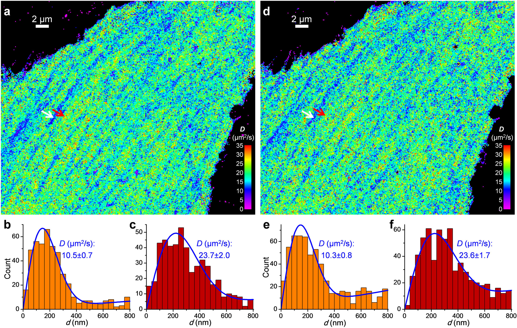
Free mEos3.2 was expressed in the cytoplasm of a PtK2 cell, and SMdM was performed on the same cell at a low single-molecule density of ~0.05 molecules/μm2/frame for 60,000 pairs of pulses (a-c), or at a high single-molecule density of ~0.11 molecules/μm2/frame for 30,000 pairs of pulses (d-f) by increasing the power of the photoactivation (405 nm) laser. (a) SMdM diffusivity map for the low single-molecule density experiment, obtained by spatially binning the single-molecule displacement d data onto 120×120 nm2 grids, and then individually fitting the distribution of d in each bin to eqn. 2 through MLE. (b,c) Distribution of 1-ms single-molecule displacement for two 360×360 nm2 areas inside (b; white arrow in a) and outside (c; red arrow in a) a linear structure of reduced local diffusivity, respectively. Blue lines are MLE results using eqn. 2, with resultant D and uncertainty σ labeled in each panel. (d-f) Results of the high single-molecule density experiment: comparable D values are obtained with the much-reduced number of pulse pairs, despite an increased background due to single-molecule mismatch. These experiments were independently repeated 10 times with similar results.
Extended Data Fig. 2. Additional SMdM results of free mEos3.2 in the cytoplasm of live U2OS and PtK2 cells, and correlated SMLM of the actin cytoskeleton.
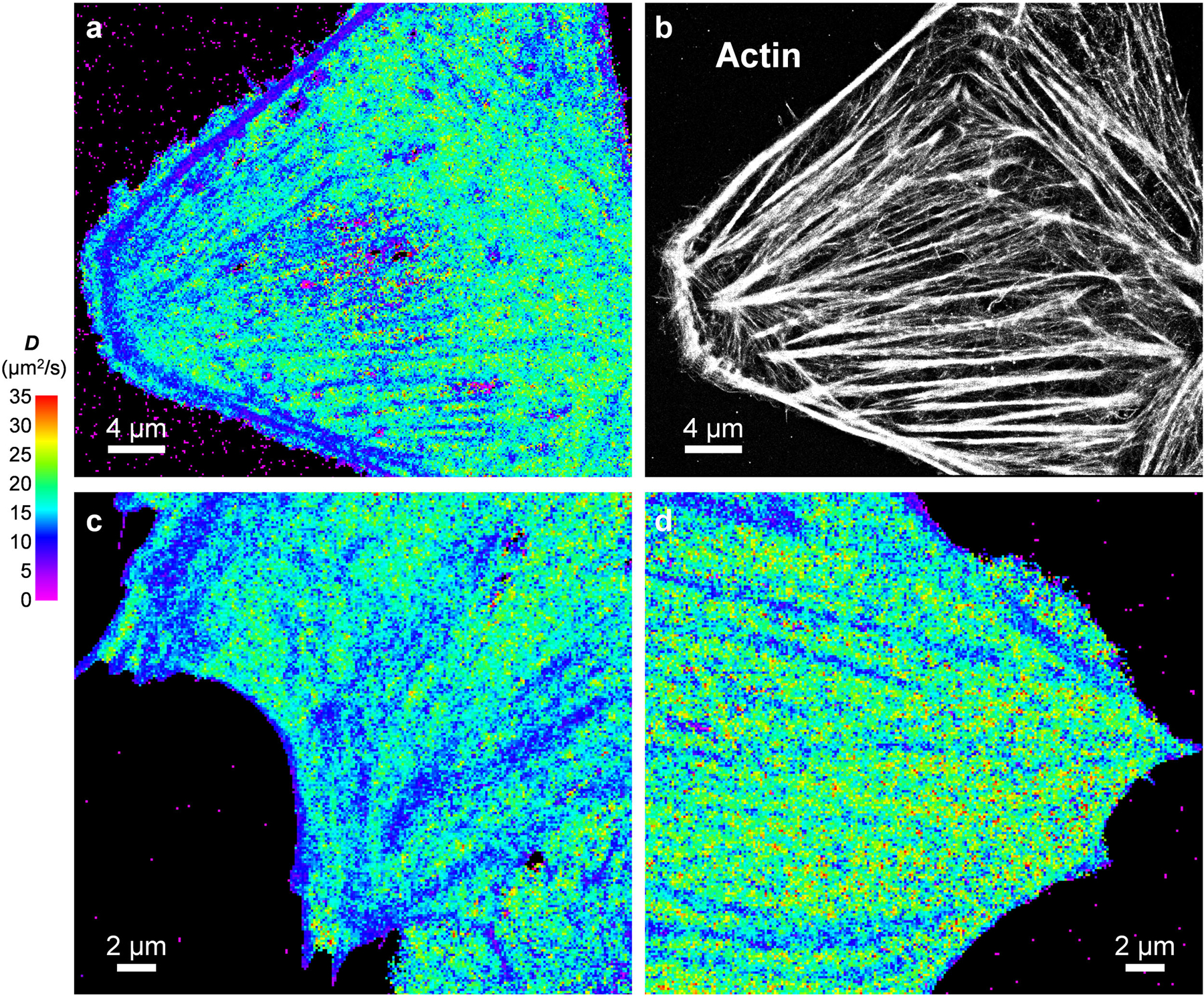
(a,b) Correlated SMdM diffusivity map for a live U2OS cell (a) vs. SMLM image of Alexa Fluor 647 phalloidin-labeled actin in the fixed cell (b). (a) and (b) were independently repeated 4 times with similar results. (c,d) Additional SMdM diffusivity maps for the cytoplasm of PtK2 cells. (c) and (d) were independently repeated 11 times with similar results.
Extended Data Fig. 3. Additional SMdM results of free mEos3.2 in the nuclei of live PtK2 cells, and correlated SMLM of DNA.
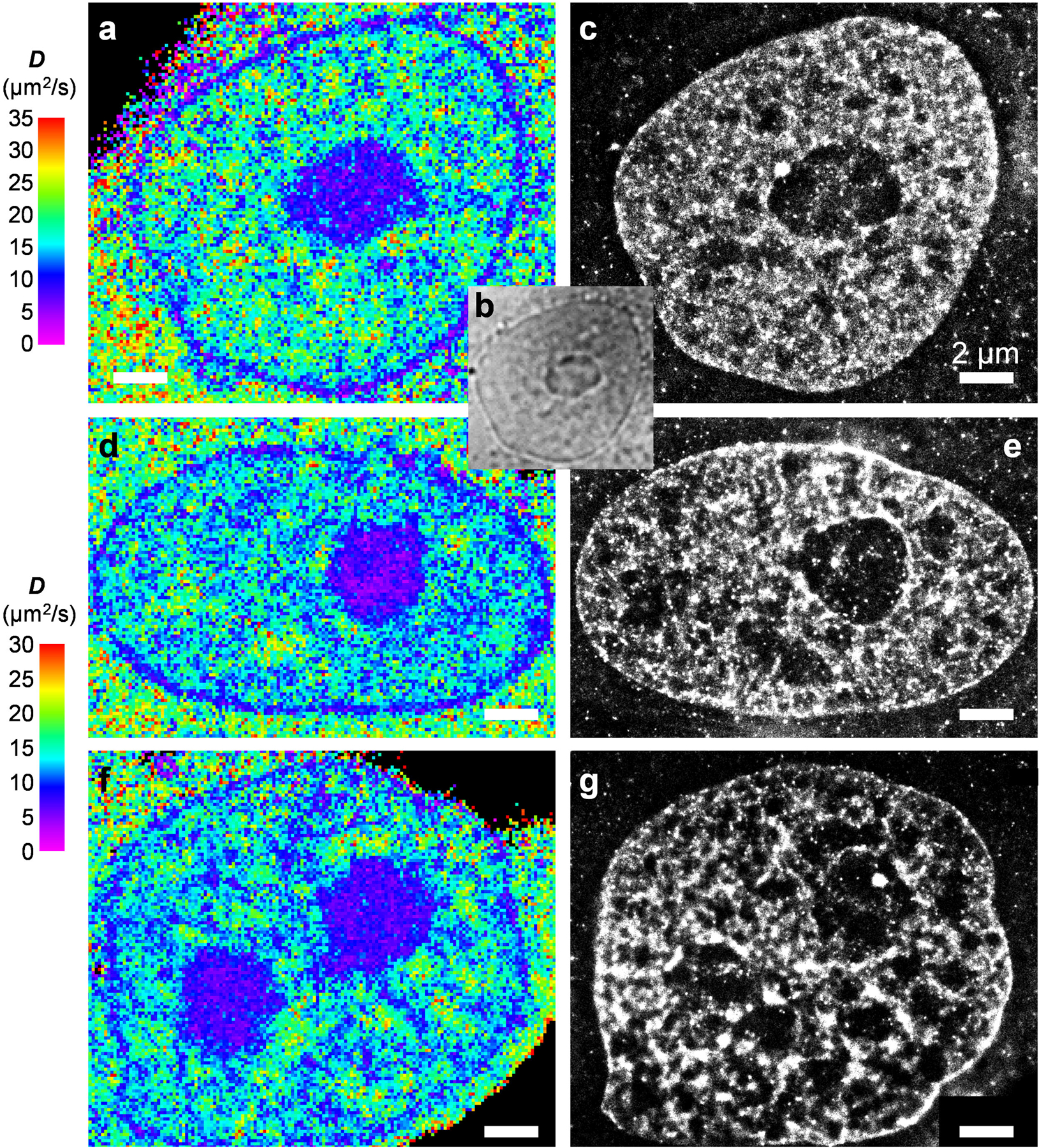
(a,d,f) SMdM diffusivity maps of 3 different cells. (b) Bright-field transmission image of the same view as (a), visualizing the nucleolus. (c,e,g) SMLM images of the fixed cells in (a,d,f) using the DNA stain NucSpot Live 650. We note that as the SMLM of DNA was performed after fixation and multiple washing steps, it was difficult to image at exactly the same focal plane as the live-cell SMdM experiment, which accounts for some of the apparent structural mismatches. Scale bars in all panels: 2 μm. These experiments were independently repeated 23 times with similar results.
Extended Data Fig. 4. SMdM of mEos3.2-NLS and correlated SMLM of DNA.
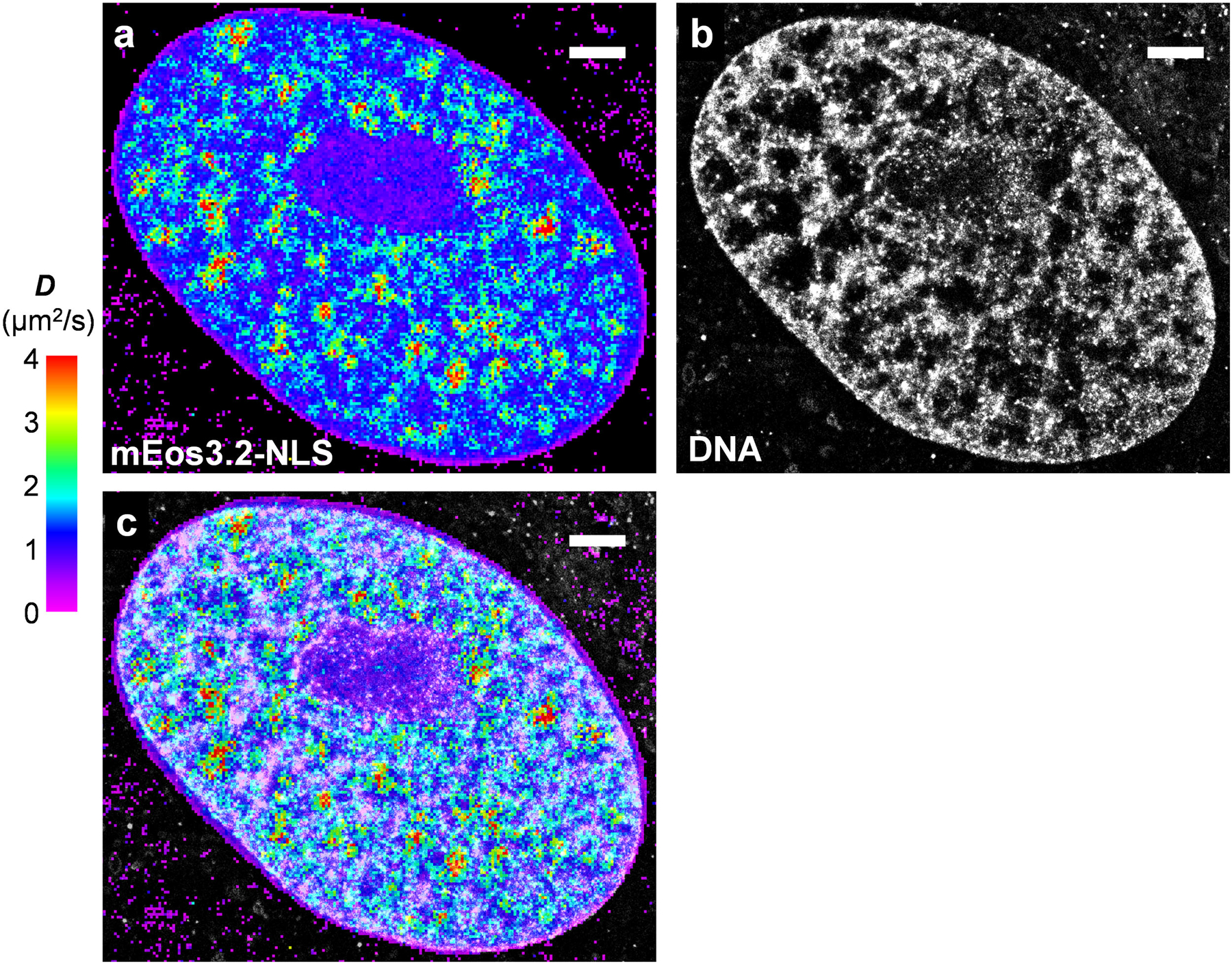
(a) SMdM diffusivity map of mEos3.2-NLS in the nucleus of a live PtK2 cell. (b) SMLM image of the fixed cell using the DNA stain NucSpot Live 650. (c) Overlay of (a) and (b). Scale bars: 2 μm. These experiments were independently repeated 18 times with similar results.
Extended Data Fig. 5. SMdM of free mEos3.2 using 488 nm excitation without photoactivation.
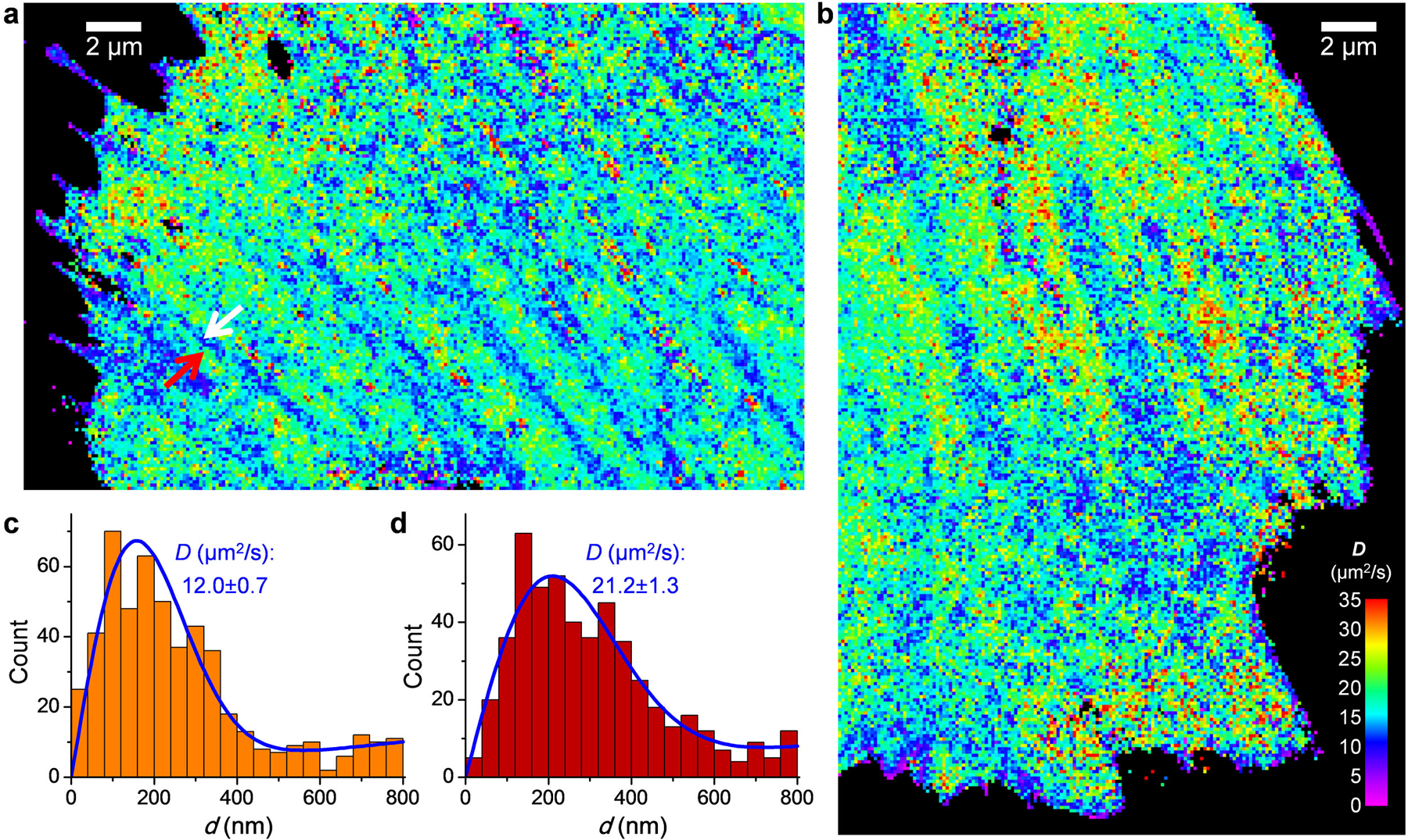
(a,b) SMdM diffusivity maps of mEos3.2-C1 in the cytoplasm of live PtK2 cells, obtained by exciting the un-photoconverted, “green” form of mEos3.2 single molecules with 488 nm excitation. (a) and (b) were independently repeated 6 times with similar results. (c,d) Distribution of 1-ms single-molecule displacement for two 360×360 nm2 areas inside (c; white arrow in a) and outside (d; red arrow in a) a linear structure of reduced local diffusivity, respectively. Blue lines are MLE results using eqn. 2, with resultant D and uncertainty σ labeled in each panel.
Extended Data Fig. 6. Asymmetric effects of negative and positive net charges on intracellular diffusion.
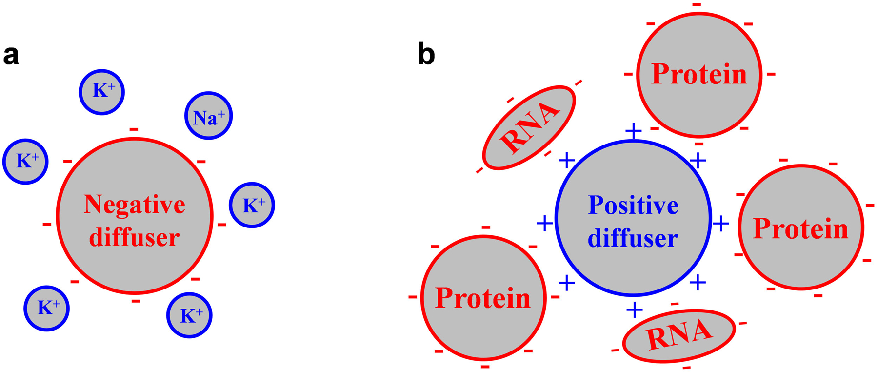
(a) A negatively charged diffuser is readily neutralized by the abundant, small metal cations inside the cell, and so diffuses similarly as neutral counterparts. (b) A positively charged diffuser is not effectively neutralized/screened by the very limited amount of intracellular small anions; its dynamic interactions with the negatively charged, large biomolecules insides the cell substantially hinder diffusion.
Supplementary Material
Acknowledgments
We thank S. Moon for discussion, and M. He and Y. Shyu for help with preparation of the DNA constructs. This work was supported by the National Institute Of General Medical Sciences of the National Institutes of Health (DP2GM132681), the Beckman Young Investigator Program, and the Packard Fellowships for Science and Engineering, to K.X. K.X. is a Chan Zuckerberg Biohub investigator.
Footnotes
Competing interests
The authors declare no competing financial interests.
References
- 1.Kuimova MK et al. Imaging intracellular viscosity of a single cell during photoinduced cell death. Nat. Chem 1, 69–73 (2009). [DOI] [PubMed] [Google Scholar]
- 2.Ebbinghaus S, Dhar A, McDonald D & Gruebele M Protein folding stability and dynamics imaged in a living cell. Nat. Methods 7, 319–323 (2010). [DOI] [PubMed] [Google Scholar]
- 3.Wirth AJ & Gruebele M Quinary protein structure and the consequences of crowding in living cells: Leaving the test-tube behind. Bioessays 35, 984–993 (2013). [DOI] [PubMed] [Google Scholar]
- 4.Yang ZG et al. Macro-/micro-environment-sensitive chemosensing and biological imaging. Chem. Soc. Rev 43, 4563–4601 (2014). [DOI] [PubMed] [Google Scholar]
- 5.Boersma AJ, Zuhorn IS & Poolman B A sensor for quantification of macromolecular crowding in living cells. Nat. Methods 12, 227–229 (2015). [DOI] [PubMed] [Google Scholar]
- 6.Rivas G & Minton AP Macromolecular crowding in vitro, in vivo, and in between. Trends Biochem. Sci 41, 970–981 (2016). [DOI] [PMC free article] [PubMed] [Google Scholar]
- 7.Lippincott-Schwartz J, Snapp E & Kenworthy A Studying protein dynamics in living cells. Nat. Rev. Mol. Cell Biol 2, 444–456 (2001). [DOI] [PubMed] [Google Scholar]
- 8.Ishikawa-Ankerhold HC, Ankerhold R & Drummen GPC Advanced fluorescence microscopy techniques-FRAP, FLIP, FLAP, FRET and FLIM. Molecules 17, 4047–4132 (2012). [DOI] [PMC free article] [PubMed] [Google Scholar]
- 9.Digman MA & Gratton E Lessons in fluctuation correlation spectroscopy. Annu. Rev. Phys. Chem 62, 645–668 (2011). [DOI] [PMC free article] [PubMed] [Google Scholar]
- 10.Ries J & Schwille P Fluorescence correlation spectroscopy. Bioessays 34, 361–368 (2012). [DOI] [PubMed] [Google Scholar]
- 11.Machan R & Wohland T Recent applications of fluorescence correlation spectroscopy in live systems. FEBS Lett 588, 3571–3584 (2014). [DOI] [PubMed] [Google Scholar]
- 12.Krieger JW et al. Imaging fluorescence (cross-) correlation spectroscopy in live cells and organisms. Nat. Protoc 10, 1948–1974 (2015). [DOI] [PubMed] [Google Scholar]
- 13.Enderlein J, Gregor I, Patra D, Dertinger T & Kaupp UB Performance of fluorescence correlation spectroscopy for measuring diffusion and concentration. ChemPhysChem 6, 2324–2336 (2005). [DOI] [PubMed] [Google Scholar]
- 14.Eggeling C et al. Direct observation of the nanoscale dynamics of membrane lipids in a living cell. Nature 457, 1159–1162 (2009). [DOI] [PubMed] [Google Scholar]
- 15.Sezgin E et al. Measuring nanoscale diffusion dynamics in cellular membranes with super-resolution STED-FCS. Nat. Protoc 14, 1054–1083 (2019). [DOI] [PubMed] [Google Scholar]
- 16.Manley S et al. High-density mapping of single-molecule trajectories with photoactivated localization microscopy. Nat. Methods 5, 155–157 (2008). [DOI] [PubMed] [Google Scholar]
- 17.Chenouard N et al. Objective comparison of particle tracking methods. Nat. Methods 11, 281–289 (2014). [DOI] [PMC free article] [PubMed] [Google Scholar]
- 18.Kusumi A, Tsunoyama TA, Hirosawa KM, Kasai RS & Fujiwara TK Tracking single molecules at work in living cells. Nat. Chem. Biol 10, 524–532 (2014). [DOI] [PubMed] [Google Scholar]
- 19.Cognet L, Leduc C & Lounis B Advances in live-cell single-particle tracking and dynamic super-resolution imaging. Curr. Opin. Chem. Biol 20, 78–85 (2014). [DOI] [PubMed] [Google Scholar]
- 20.Manzo C & Garcia-Parajo MF A review of progress in single particle tracking: from methods to biophysical insights. Rep. Prog. Phys 78, 124601 (2015). [DOI] [PubMed] [Google Scholar]
- 21.Elf J & Barkefors I Single-molecule kinetics in living cells. Annu. Rev. Biochem 88, 635–659 (2019). [DOI] [PubMed] [Google Scholar]
- 22.Milo R & Phillips R Cell Biology by the Numbers (Garland Science, New York, NY, 2016). [Google Scholar]
- 23.Elf J, Li GW & Xie XS Probing transcription factor dynamics at the single-molecule level in a living cell. Science 316, 1191–1194 (2007). [DOI] [PMC free article] [PubMed] [Google Scholar]
- 24.English BP et al. Single-molecule investigations of the stringent response machinery in living bacterial cells. Proc. Natl. Acad. Sci. U. S. A 108, E365–E373 (2011). [DOI] [PMC free article] [PubMed] [Google Scholar]
- 25.Rust MJ, Bates M & Zhuang X Sub-diffraction-limit imaging by stochastic optical reconstruction microscopy (STORM). Nat. Methods 3, 793–795 (2006). [DOI] [PMC free article] [PubMed] [Google Scholar]
- 26.Betzig E et al. Imaging intracellular fluorescent proteins at nanometer resolution. Science 313, 1642–1645 (2006). [DOI] [PubMed] [Google Scholar]
- 27.Hess ST, Girirajan TPK & Mason MD Ultra-high resolution imaging by fluorescence photoactivation localization microscopy. Biophys. J 91, 4258–4272 (2006). [DOI] [PMC free article] [PubMed] [Google Scholar]
- 28.Zhang MS et al. Rational design of true monomeric and bright photoactivatable fluorescent proteins. Nat. Methods 9, 727–729 (2012). [DOI] [PubMed] [Google Scholar]
- 29.Swaminathan R, Hoang CP & Verkman AS Photobleaching recovery and anisotropy decay of green fluorescent protein GFP-S65T in solution and cells: Cytoplasmic viscosity probed by green fluorescent protein translational and rotational diffusion. Biophys. J 72, 1900–1907 (1997). [DOI] [PMC free article] [PubMed] [Google Scholar]
- 30.Xu K, Babcock HP & Zhuang X Dual-objective STORM reveals three-dimensional filament organization in the actin cytoskeleton. Nat. Methods 9, 185–188 (2012). [DOI] [PMC free article] [PubMed] [Google Scholar]
- 31.Seksek O, Biwersi J & Verkman AS Translational diffusion of macromolecule-sized solutes in cytoplasm and nucleus. J. Cell Biol 138, 131–142 (1997). [DOI] [PMC free article] [PubMed] [Google Scholar]
- 32.Boisvert FM, van Koningsbruggen S, Navascues J & Lamond AI The multifunctional nucleolus. Nat. Rev. Mol. Cell Biol 8, 574–585 (2007). [DOI] [PubMed] [Google Scholar]
- 33.Marfori M et al. Molecular basis for specificity of nuclear import and prediction of nuclear localization. Biochim. Biophys. Acta-Mol. Cell Res 1813, 1562–1577 (2011). [DOI] [PubMed] [Google Scholar]
- 34.Xiong K & Blainey PC Molecular sled sequences are common in mammalian proteins. Nucleic Acids Res 44, 2266–2273 (2016). [DOI] [PMC free article] [PubMed] [Google Scholar]
- 35.Potma EO et al. Reduced protein diffusion rate by cytoskeleton in vegetative and polarized Dictyostelium cells. Biophys. J 81, 2010–2019 (2001). [DOI] [PMC free article] [PubMed] [Google Scholar]
- 36.Baum M, Erdel F, Wachsmuth M & Rippe K Retrieving the intracellular topology from multi-scale protein mobility mapping in living cells. Nat. Commun 5, 4494 (2014). [DOI] [PMC free article] [PubMed] [Google Scholar]
- 37.Di Rienzo C, Cardarelli F, Di Luca M, Beltram F & Gratton E Diffusion tensor analysis by two-dimensional pair correlation of fluorescence fluctuations in cells. Biophys. J 111, 841–851 (2016). [DOI] [PMC free article] [PubMed] [Google Scholar]
- 38.Bancaud A et al. Molecular crowding affects diffusion and binding of nuclear proteins in heterochromatin and reveals the fractal organization of chromatin. EMBO J 28, 3785–3798 (2009). [DOI] [PMC free article] [PubMed] [Google Scholar]
- 39.Dross N et al. Mapping eGFP oligomer mobility in living cell nuclei. PLoS One 4, e5041 (2009). [DOI] [PMC free article] [PubMed] [Google Scholar]
- 40.Schavemaker PE, Smigiel WM & Poolman B Ribosome surface properties may impose limits on the nature of the cytoplasmic proteome. eLife 6, e30084 (2017). [DOI] [PMC free article] [PubMed] [Google Scholar]
- 41.Lodish H et al. , in Molecular Cell Biology (Freeman WH, New York, 2003), pp. 253. [Google Scholar]
- 42.Zustiak SP, Nossal R & Sackett DL Hindered diffusion in polymeric solutions studied by fluorescence correlation spectroscopy. Biophys. J 101, 255–264 (2011). [DOI] [PMC free article] [PubMed] [Google Scholar]
- 43.Lawrence MS, Phillips KJ & Liu DR Supercharging proteins can impart unusual resilience. J. Am. Chem. Soc 129, 10110–10112 (2007). [DOI] [PMC free article] [PubMed] [Google Scholar]
- 44.Zhang Z, Kenny SJ, Hauser M, Li W & Xu K Ultrahigh-throughput single-molecule spectroscopy and spectrally resolved super-resolution microscopy. Nature Methods 12, 935–938 (2015). [DOI] [PubMed] [Google Scholar]
- 45.Yan R, Moon S, Kenny SJ & Xu K Spectrally resolved and functional super-resolution microscopy via ultrahigh-throughput single-molecule spectroscopy. Acc. Chem. Res 51, 697–705 (2018). [DOI] [PubMed] [Google Scholar]
- 46.Anderson CM, Georgiou GN, Morrison IEG, Stevenson GVW & Cherry RJ Tracking of cell surface receptors by fluorescence digital imaging microscopy using a charge-coupled device camera. Low-density lipoprotein and influenza virus receptor mobility at 4 °C. J. Cell Sci 101, 415–425 (1992). [DOI] [PubMed] [Google Scholar]
- 47.Kues T, Peters R & Kubitscheck U Visualization and tracking of single protein molecules in the cell nucleus. Biophys. J 80, 2954–2967 (2001). [DOI] [PMC free article] [PubMed] [Google Scholar]
- 48.Lin WC et al. H-Ras forms dimers on membrane surfaces via a protein-protein interface. Proc. Natl. Acad. Sci. U. S. A 111, 2996–3001 (2014). [DOI] [PMC free article] [PubMed] [Google Scholar]
- 49.Hansen AS et al. Robust model-based analysis of single-particle tracking experiments with Spot-On. eLife 7, e33125 (2018). [DOI] [PMC free article] [PubMed] [Google Scholar]
Associated Data
This section collects any data citations, data availability statements, or supplementary materials included in this article.
Supplementary Materials
Data Availability Statement
The data that support the findings of this study are available from the corresponding author upon reasonable request.


