

Abstract
Droplet microfluidics has enabled a significant reduction in reaction volume and analysis time, which in turn has led to transformative advances in high-capacity screening and assays. By arranging droplets into a static array, it is possible to monitor dynamic events that occur within these microchambers over an extended period of time, facilitating the identification of rare events and cell types. In many instances, it is highly desirable to recover a small number of droplets that contain unique analytes or cells for further analyses; however, few techniques allow for selective recovery of droplets from such an array without using a complex network of physical valves, which also require a large number of control units external to the microfluidic device. In this report, we present photoactivated selective release of droplets from a static microwell array enabled by a photoresponsive polymer layer integrated into the microfluidic device. This photoresponsive layer is placed in between a microwell array that traps a large number of droplets and a PDMS slab with or without a top flow channel that can be used for recovery. By using focused light, the photoresponsive layer can either be punctured for release-up recovery or induced to create a bubble by local heating to selectively push-down release droplets. We show that the photoresponsive layer is optically transparent within the visible spectrum and thus does not interfere with optical observation of droplets. The type of photoacoustic dye and the physical properties of the photoresponsive layer can be engineered to induce either puncture of the photoresponsive layer or pushing of droplets out of the microwell arrays with low thermal impact on the droplets. We believe that the photoresponsive layer will have a broad impact in the field of soft lithography-based microfluidic devices for various applications including photoresponsive valves as well as high-throughput single-cell sequencing.
Keywords: selective release, droplets, photoactivated, photoresponsive, photoacoustic, IR-780
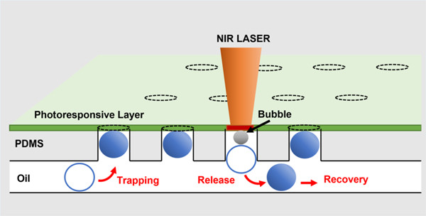
Graphical Abstract
■ INTRODUCTION
Droplet microfluidics has enabled rapid production of highly uniform emulsion droplets with a wide range of applications. In particular, individual microfluidic droplets can be used as microchambers, making them a versatile platform to perform rapid high-throughput assays while significantly reducing the volume of reagents required.1–4 Compared to conventional multi-well plate-based assays, the required reagent volume can be reduced by three to five orders of magnitude, and the per-sample manipulation time can also be reduced by up to ten-folds.1,5–7 Several applications including single-cell gene regulation, nuclear division, and metabolism study require culturing of cells or monitoring dynamic events within droplets for extended periods from hours to days. Various types of static array devices have been developed for such applications, which allow for real time dynamic observation of events that occur within the droplets.8–12
For a number of applications that involve trapping droplets in a microwell array for extended periods, it is highly beneficial and desirable to recover droplets following the observation. For example, selective release of droplets that contain a single cell or multiple cells that show a rare phenotype could enable single-cell sequencing and potentially uncover the molecular basis of such a phenotype. A handful of methods have been developed for the selective recovery of droplets from a microwell array. The recovery methods depend highly on the trapping methods that are used for dynamic monitoring or droplet incubation.8,13–19 In case of the so-called pea-in-a-pod device, where droplets are guided through and physically trapped in a corrugated channel, selective recovery is not possible without using some type of barcode or labels within each droplet; such post hoc selection from barcode is inefficient if the phenotype is rare.25 For a device with microwell arrays that captures droplets by density difference, droplets can be released by simply flipping the device; however, this method is non-specific, and does not enable selective recovery.20,21 Currently, the most effective method for selective recovery of droplets is based on mechanical actuation using pneumatic valves.10,13,14,22 Mechanical actuation can trap and release droplets in both two-dimensional and three-dimensional arrays with considerable accuracy and precision. However, the applicability of this approach is potentially limited by the fact that the number of valves must at least match the number of microwells. This would require a rather complicated device fabrication process and also require sophisticated equipment to control and deliver pressure to the necessary set of valves to enable selective release. Due to these limitations, the capacity for capture and selective release based on this approach has been limited to a few hundreds, whereas many high-capacity applications including rare cell phenotyping require monitoring at least a few thousand droplets.
In this report, we develop a method to capture and selectively release droplets from a microwell array by combining a photoresponsive layer with the conventional microfluidic device fabrication technique. The photoresponsive layer, made of a glassy polymer, polystyrene, a photoresponsive dye, and a plasticizer, is sandwiched in between the microwell array and a PDMS slab with or without a top flow channel that is used to apply positive or negative pressure. The glass transition temperature and absorption spectra of the photoresponsive layer can be engineered to address a variety of experimental needs. Furthermore, the incorporation of the photoresponsive layer minimally alters the chip fabrication process, and the selective recovery of samples can be performed without relying on a large number of supporting instruments. Previous studies have incorporated aluminum patterns that serve as heating blocks into a device or used focused UV laser to heat the oil interface adjacent to the droplet to release droplets.14,23 We use NIR laser, which is far less harmful to biological molecules and cells than UV laser. We demonstrate photoactivated selective release (PHASR) of droplets from a photoresponsive layer-embedded array consisting of 4400 microwells, which we believe is the largest capacity reported for dynamic observation with selective recovery to date. With a slight modification on the laser intensity and the focal plane, we show that two different ways of recovery are possible. A high-intensity focused laser on the photoresponsive layer allows release-up recovery of the droplet, whereas a low-intensity focused laser on the photoresponsive layer−oil interface induces push-down recovery of droplets. Moreover, this method does not require any extra instruments that scale with the number of microwells. Thus, we anticipate that the PHASR method enabled in this high-capacity system will benefit many research fields utilizing phenotyping in combination with genotyping such as molecular biology and immunology.
EXPERIMENTAL METHODS
Reagents
Polystyrene (PS) with a molecular weight (MW) of 192,000, trichloro(1H,1H,2H,2H-perfluorooctyl)silane (PFOTS), di(ethylene glycol) dibenzoate (DEGD), IR-780 iodide (IR-780), and silicon 2,3-naphthalocyanine bis(trihexylsilyloxide) (SiNc) were purchased from Sigma-Aldrich, MO, USA. Polydimethylsiloxane (PDMS) was purchased from Dow Corning Corp., MI, USA. FC-40 oil containing 2% EA-surfactant (Pico-Surf) was purchased from Dolomite Microfluidics, United Kingdom. EL4 (ATCC TIB-39) mouse lymphoma cell line, ATCC-formulated Dulbecco’s Modified Eagle’s medium, and horse serum were purchased from American Type Cell Culture, VA, USA. Live/Dead mammalian cell viability assay kit was purchased from Thermo Fisher Scientifics, MA, USA.
Device Fabrication
The device masks are designed using AutoCAD 2018 and printed by CAD/Art Service, Inc. (CA, USA). A master mold is fabricated on a 3″ silicon wafer (University Wafer Inc., MA, USA) using the conventional soft lithography technique. The master molds are all fabricated inside a cleanroom in the Quattrone Nanofabrication Center of the Singh Center of Nanotechnology at the University of Pennsylvania. A positive photoresist KMPR-1050 (MicroChem, MA, USA) is used, and the thickness of the molds is controlled by adjusting the rotation speed of spin coating in conjunction with the UV exposure time under a mask aligner (SUSS Microtec, Garching, Germany). To produce the master for the bottom trap channel, a multilayer mold fabrication method is employed. Multilayer mold fabrication skips mold development after initial post-bake and proceeds with spin coating of the second photoresist layer. The top flow channel and droplet generator molds are fabricated via the single-layer soft lithography technique. Fabricated master molds are subsequently silanized with trichloro(1H,1H,2H,2H-perfluorooctyl)-silane (PFOTS) to facilitate the detachment of cured polydimethylsiloxane (PDMS). Polydimethylsiloxane (PDMS) precursor is prepared by mixing the base and curing agents of Sylgard 184 (Dow Corning Corp, MI, USA) in a 10:1 ratio and is degassed in a vacuum chamber for 30 min.
The degassed PDMS mixture is poured onto the master molds. The thicknesses of poured PDMS for the droplet generator and top flow channel are ∼3 and ∼1 mm, respectively. The thickness of poured PDMS for the bottom trap channel is just enough to completely cover the channel structures. All molds are placed in an aluminum foil pan and degassed for another 30 min. After degassing, the top flow channel mold and the droplet generator mold are kept in an oven for 4 h at 65 °C. The droplet generator PDMS is bonded to a plain glass slide using a conventional oxygen plasma treatment. A thin clear polyester film is slowly placed on top of the uncured PDMS on the bottom trap channel while minimizing bubble formation. A 2 × 3″ glass slide is placed on top of the film, and then binder clips and a three-prong clamp are used to apply compressive pressure onto the sandwiched layers of the glass slide, polyester film, PDMS solution, and the wafer with the bottom trap channel mold. The clamped device is left at room temperature for 1 h to allow uncured PDMS to completely squeeze out and then placed in an 80 °C oven for 2 h. Fully cured bottom trap channel PDMS is peeled off from the master mold under ethanol. The polyester film is left on the bottom trap channel. Other PDMS layers are peeled and prepared using the standard. The base of bottom trap channel is taped with scotch tape to keep the surface clean.
The photoresponsive layer is fabricated using polystyrene (PS) of MW 192,000 and di(ethylene glycol) Dibenzoate (DEGD) with IR-780 iodide (Sigma-Aldrich, MO, USA). Two dyes are tested in the study with target actuation spectra in the near-infrared region: IR-780 and silicon 2,3-naphthalocyanine bis(trihexylsilyloxide) (SiNc). To render PS responsive to near-infrared (NIR) light, we use a photoacoustic dye such as IR-780 iodide (MW ∼667 g/mol) or silicon 2,3-naphthalocyanine bis(trihexylsilyloxide) (SiNc) (MW ∼1340 g/mol). Both are well-known photoacoustic dyes in the range of NIR with extinction coefficients greater than 250,000 M−1 cm−1. In 10 mL of chloroform, 5 wt % PS, 1.45 wt % DEGD, and 0.1 wt % IR-780 are added. The glass transition temperature of PS is 90−100 °C, which likely is too high for use in the proposed scheme. To ensure that PS responds to light at a more reasonable temperature such that the generated heat would not damage the encapsulated molecules or cells, we add a plasticizer, di(ethylene glycol) dibenzoate (DEGD) (MW ∼314 g/mol). DEGD is added to the PS solution at 1.45 wt %, which is equivalent to 29 wt % of the mass of PS. In addition to 1.45 wt % of DEGD, which lowers the glass transition temperature of the polymer, IR-780 at its solubility limit in chloroform (0.1 wt %) is added. The solution is left in a mixer and sonicating bath for 1 h each. Subsequently, the solution is filtered through a 5 μm PTFE syringe filter. The solution is stored in a tightly sealed vial with aluminum foil covering to prevent photobleaching of the photoacoustic dye. A thin photoresponsive layer is prepared using a flow coater. A clean glass slide is placed on a doctor blade coater (NRT100, ThorLab, NJ, USA). Approximately 2 mL of the photoacoustic solution is evenly cast on 2″ × 3″ glass slides using a coating speed of 20 mm/sec and an acceleration of 1 mm/sec2.
The chip assembly process starts with bonding of the bottom trap channel PDMS with the photoresponsive layer. The overview of the fabricated device and fabrication step protocol is schematically shown in Figure 1A. The vacuum-dried photoacoustic layer on a glass slide and the top of the bottom trap channel are oxygen plasma treated at 50 W for 45 s (SCE 110, Anatech Ltd., MI, USA) and bonded together as shown in Figure 1B-(b). The bonded device is left undisturbed for 2 h to ensure bonding, and then the device is carefully peeled off from the glass slide. This bonding between the photoresponsive layer and the bottom trap channel PDMS is irreversible, and thus these layers cannot be easily separated. The inlets and outlets for the composite of the bottom trap channel and photoresponsive layer and the top flow channel are punched using a 1.0 mm disposable biopsy punch (Integra Miltex, NJ, USA). The base side of the top flow channel is bonded onto the photoresponsive layer using the same oxygen plasma treatment and stored for an additional 2 h; this bonding requires alignment of the bottom trap channel structure to the top flow channel structure and can be performed with high fidelity under a mask aligner or stereoscope. In case of weak bonding between the photoresponsive layer and the top flow channel device, treatment of 5 v/v% (3-aminopropyl)-triethoxysilane (APTES) on the photoresponsive layer following plasma treatment is recommended. After removing the scotch tape, the base of the bottom trap channel is bonded to a glass slide. To enable use under a high-pressure flow system, 1/16″ clear acrylic plate can be custom-tailored (PLS 4.75, Universal Laser Systems, AZ, USA) and bonded with the base glass slide using 5 min epoxy.
Figure 1.

PHASR device fabrication protocol. (A) Fabrication protocol for the PHASR device. The first composite laminate is prepared by bonding the photoresponsive layer with the bottom PDMS trap channel, the second composite laminate is prepared by bonding the first composite with the top PDMS flow channel, and the final device is prepared by bonding the second composite to a glass slide. (B) Images of (a) bottom PDMS trap channel showing wells with open-top structure and (b) bottom PDMS trap channel with a photoresponsive layer; the photoresponsive layer covers the microwell array. Images of parts in panel (A) enclosed with dotted boxes are shown in panel (B).
Cell Culture
EL4 (ATCC TIB-39) mouse lymphoma cell line was purchased from American Type Cell Culture, VA, USA. The thawed cell pellet is suspended in ATCC-formulated Dulbecco’s Modified Eagle’s Medium supplemented with horse serum final concentration of 10%. The cell suspension is seeded in a Corning T-75 flask at density of 1.5 × 10⁵ cells/mL with total volume of 20 mL. The seeded flask is incubated at 37 °C with 5% CO2 concentration for 48 h. The cell suspension is mixed with a serological pipette to form homogeneous suspension and the concentration is measured using a hemocytometer. The cell suspension is centrifuged at 90 rcf for 10 min without break, and the supernatant is removed. The cell pellet is resuspended in a growth medium to a density of 1.2 × 10⁷ cells/mL.
Droplet Generation and Trapping
A droplet generator made with PDMS is silanized with 2% PFOTS solution in FC-40 oil for 5 min following plasma treatment. The device is flushed with neat FC-40 oil then connected with two PTFE tubings, each connected to a syringe, one filled with FC-40 containing 2 wt % EA-surfactant, and the other filled with aqueous solution with or without dye. The EA surfactant is a commercially available tri-block copolymer composed of perfluor-opolyether (PFPE) and polyethylene glycol (PEG) blocks and is most widely used in emulsion stabilization in fluorinated oils like FC-40 and HFE-7500. An aqueous dye such as dimethyl blue can be added to facilitate the visualization of the droplets. Flow rates of 250 and 200 μL/h are used for oil and aqueous phases, respectively. For cell viability assay, cell suspension with a density of 1.2 × 10⁷ cells/mL and Live/Dead mammalian cell viability assay kit (Thermo Fisher Scientifics, MA, USA) are used as aqueous phases. Aqueous phases are separately introduced into the droplet generator. For the Live/Dead mammalian cell viability assay, the concentrations of EthD-1 and calcein AM are adjusted to 8 and 4 μM, respectively, to produce the final concentrations of 4 and 2 μM in droplets. Prior to the droplet introduction, the PHASR device is flushed with neat FC-40 for 2 min to remove air bubbles within the device. In addition, the FC-40 oil phase with 2% PFOTS is flown into the PHASR device to make the channel hydrophobic and prevent droplet adhesion to the channel wall. Droplets generated from the droplet generator travel through a PTFE tubing and enter the bottom trap channel of the PHASR device. With >60% of the wells filled with droplets, the droplet injection tubing is disconnected, and neat FC-40 oil is injected slowly to fill the remaining wells with the droplets. The flow rate of the oil phase is increased to 500 μL/h to remove untrapped droplets from the channel.
Selective Release of Droplets
All selective release and recovery experiments are conducted at the Vision Research Center of the University of Pennsylvania. To selectively release droplets, we use a home-built two-photon microscope, since the two-photon microscope ensures precise targeting of a specific location within the PHASR device with minimal off-target effects. The mode-locked Titanium:Sapphire (Ti:Al2O3) laser (Chameleon, Coherent, Santa Clara, CA) is used as an excitation source with the wavelength of 780 nm for IR-780-based photoresponsive layers. The laser has an output power of 3.37 J/s at 780 nm wavelength, and the pass-through percent of the power is calculated to be roughly 20% of the output. The laser source is Spectra Physics Mai Tai HP 1020 pulsed laser, equipped with DeepSee automated group velocity dispersion compensation. The laser repetition rate is 80 MHz at 800 nm wavelength; the duration of a pulse is less than 100 fs with the peak power greater than 300 kW. Under 60× water-immersion objective, 5% intensity corresponds to 73.9 J/s·cm2 exposure intensity. In case of a SiNc-based photoresponsive layer, the wavelength is tuned to 775 nm. Several parameters such as laser intensity, laser power, scanning resolution, and scanning rate affect the performance of the PHASR device. To represent the laser exposure in a single parameter, we first calculate the total energy exposure rate in the unit of W/cm2 and multiply this value by the exposure time to determine the total exposure energy per unit area in the unit of J/cm2. We test ranges of exposure intensity and time for each photoresponsive layer and determine that the exposure energy of 155.03 J/cm2 is necessary to release 50 μm droplets from 50 μm depth wells using the 17 μm IR-780-based photoresponsive layer. The target is identified within the field of view using a low-magnification objective such as 4× or 10×, and then the objective is replaced with a 60× water-immersion objective to zoom-in on the target. The schematics of droplet trapping and release via the two mechanisms are shown in Figure 2B,C. Depending on the method of recovery, the focal plane is set either at the top of the photoresponsive layer to induce hole formation or at the base for bubble formation. Droplets released from the microwell array are recovered by flowing oil through the channel.
Figure 2.
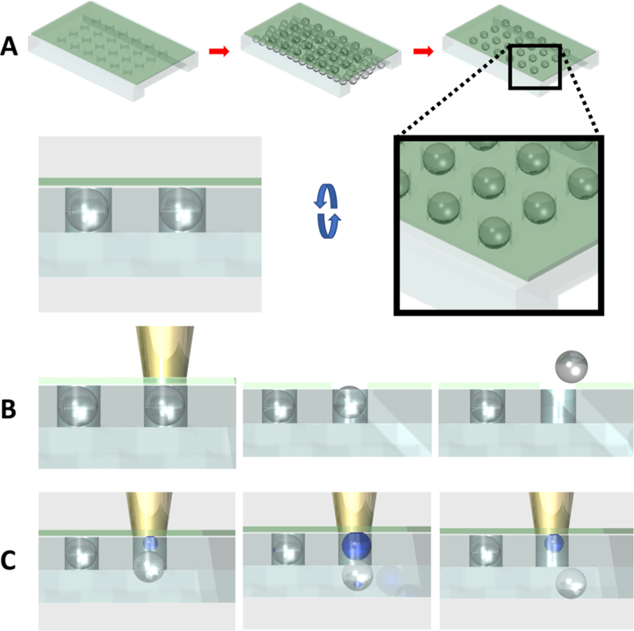
PHASR device overview. (A) Droplet static array formation by density difference. The higher density of the oil phase drives trapping of aqueous droplets in wells. (B) NIR laser irradiation on the top of the photoresponsive layer heats and punctures the layer, allowing a droplet to float through the opening and into the top flow channel for release-up recovery. (C) NIR laser exposure on the bottom of the photoresponsive layer creates a bubble, which pushes out the droplet toward the bottom trap channel for push-down recovery.
RESULTS AND DISCUSSION
Droplet microfluidics can readily isolate cells, particles, and even single molecules into individual droplets, which can subsequently be arranged into an array that enables monitoring of dynamic events such as cell response to external stimuli or (bio)chemical reactions. The photoresponsive layer-enabled photoactivated selective release (PHASR) of droplets from a microwell array, which we explore in this study, is schematically illustrated in Figure 2. We use density difference between continuous and dispersed phases to trap droplets into a microwell array as shown in Figure 2A. The trapping efficiency of using this method is approximately 20%, which agrees well with a previous report.24 The trapping efficiency can be improved drastically (up to 90%) by slightly tilting the chip back and forth.23 The trapping efficiency can vary greatly depending on the droplet velocity and the volume fraction of the droplets in the emulsion suspension. This method is advantageous over other methods of droplet trapping because of the ease of device fabrication. The target droplets for further investigation can be identified through optical measurements of individual cells in the microwell array. These measurements can be taken over time, for example, using physiological reporter probes. The microwell array is fully compatible with an environmental chamber capable of full gas and humidity control. Once the targets are identified, they can be released from the microwell array using two different methods as illustrated in Figure 2B,C. High intensity short burst light can be focused onto the photoresponsive layer to induce rupture of the photoresponsive layer over specific microwells that contain the target droplets (Figure 2B); droplets can float through the pore and escape the microwell or they can be pushed downward and released by applying positive pressure from the top flow channel. If moderate intensity light is focused onto the photoresponsive layer above a selected well, this will lead to bubble formation, which in turn pushes out the droplet from the array as illustrated in Figure 2C. We believe that the bubble formation upon laser exposure is likely a result of cavitation in the oil phase.25 In case of the layer rupture-induced release-up recovery, the order of droplet release can be random as there is little concern for recapturing of droplets, whereas in the case of the push-down release, the droplets should be released sequentially in the direction of the flow to prevent droplets from being recaptured by empty microwells.
The device fabrication involves fabrication of three individual layers—the bottom trap channel consisted of a microwell array made of polydimethylsiloxane (PDMS), the middle photoresponsive layer made of polystyrene (PS), and the top PDMS slab with or without a top flow channel—followed by their sequential bonding as shown in Figure 1. To enable release of droplets through a punctured photoresponsive layer, the bottom trap PDMS channel must have an open-top structure. Even a thin layer of PDMS on the top of each microwell will not allow release of droplets through the punctured photoresponsive layer. To ensure complete open-top structure in the PDMS channel, uncured PDMS, poured on the master, is compressed between a polyester film and the hard master using a three-prong laboratory clamp, applying pressure of approximately 7 kPa. Given sufficient time, uncured PDMS squeezes out of the space between the polyester film and the patterned photoresist completely. A minimum of 1 h is used to ensure that the microwell array layer has an open-top structure as shown in Figure 1B-(a). Although our demonstration of selective release will be performed with a PHASR device with 4400 wells, we can readily fabricate a PDMS microwell array with up to 40,000 open-top wells. The solvent-cast photoresponsive layer serves as the top surface (i.e., ceiling) of the bottom trap channel PDMS layer with open-top microwells as shown in Figure 1B-(b). To enable layer rupture-induced release-up recovery, we add a PDMS slab with a top flow channel atop the photoresponsive layer. The push-down release device does not require such a top flow channel structure. Layers are bonded via oxygen plasma treatment, and optional epoxy-based sealing can be added for systems that deal with high pressure flows.
The most essential component of this PHASR device is the photoresponsive layer. We chose to use a glassy thermoplastic polymer, polystyrene (PS), as the base material for this purpose. PS is chosen because free-standing films of PS can be readily prepared by using highly entangled PS.26 Moreover, its thermomechanical properties can be engineered by incorporating a plasticizer. These dyes also have high solubility in good solvents for PS such as chloroform and tetrahydrofuran. Although the quantum yields for these two dyes have not been reported, dyes with similar structures such as IR-800 have quantum yields of 0.03433,34, indicating that much of the absorbed energy is dissipated via thermal mechanisms, leading to heat generation.
The polymer solution along with the plasticizer and one of the two photoacoustic dyes remains clear and optically transparent during preparation, indicating high solubility of the three components in chloroform. The doctor blade method is used to coat the solution onto a clean glass slide. The film is dried under vacuum to completely remove the solvent, leading to the formation of an optically transparent and slightly green solid film. The addition of DEGD reduces the glass transition temperature (Tg) of PS significantly to 33 °C, and the addition of the photosensitive dye does not significantly change the Tg as seen in Figure 3.35 The suppression of 60 °C in Tg agrees well with previously reported results.27 This study mainly uses a photoresponsive layer with a Tg of 33 °C to minimize the potential heat damage on living cells in droplets. If the device requires incubation or imaging at 37 °C, the composition of the photoresponsive layer can be easily adjusted to achieve a Tg of ∼40 °C.
Figure 3.

Characteristics of photoresponsive layer with the IR-780 dye. (A) Tg PS layer, PS layer with DEGD, and PS layer with DEGD and IR-780 dye measured via dynamic mechanical analysis (DMA). (B) Thickness of the photoresponsive layer as a function of the number of flow coating as determined by profilometry.
Since thin photoresponsive layers would be advantageous in the rupture-induced release-up recovery method, we test layer thicknesses ranging from 100 nm to 30 μm and find that layers with a thickness less than 15 μm result in unreliable fabrication due to layer deterioration during either plasma treatment or peel-off process. We determine that the minimum thickness that results in highly reliable device fabrication (success rate > 90%) to be approximately 17 μm. The solution concentration of PS and the blade coating condition (gap height = 200 μm, speed of blade translation = 20 mm/s, polymer concentration = 5 wt %) are thus adjusted to give a 17 μm PS film. The thickness of the PS layer can be increased in ∼14 μm increments with additional coatings as shown in Figure 3.
We also assess the optical properties of the layer as shown in Figure 4. The FTIR spectra of the layers confirm the incorporation of DEGD as can be seen by the peaks at 1110, 1280, and 1720 cm−1, which correspond to the secondary alcohol C−O, aromatic ester C−O, and carboxylic acid C=O, respectively, of DEGD. More importantly, the UV−visible (UV−Vis) spectra show that the addition of the photoacoustic dye IR-780 significantly increases the light absorption in the range of 700−900 nm wavelength while maintaining a large window of transparency in the visible range, which is important to ensure direct monitoring of droplets using optical and/or fluorescence microscopy. If a maximum fluorescence signal is necessary, an inverted microscope can be used to minimize the light-path absorption from the photoresponsive layer.
Figure 4.
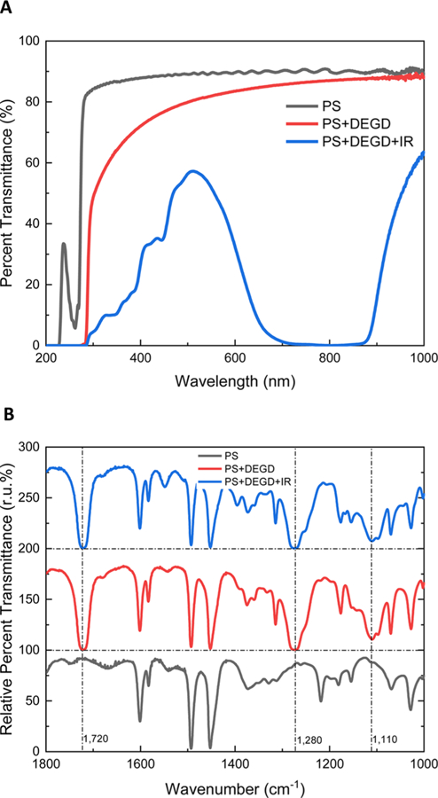
Optical characterization of photoacoustic dye-incorporating PS layer. (A) UV−Vis spectra of the PS layer, PS layer with DEGD, and PS layer with DEGD and IR-780. The suppressed transmittance region is highlighted with a red box. (B) FTIR spectra of the PS layer, PS layer with DEGD, and PS layer with DEGD and IR-780 dye. The three spectra are offset by 100% for peak visualization.
The key feature of the PHASR device is the capability to specifically and locally heat the photoresponsive layer to puncture the photoresponsive layer or push out the targets from the selected microwells. With two different photoacoustic dyes, we test the ranges of parameters that enable selective release. The IR-780 dye is used primarily in this study because of its low cost and commercial availability. A home-built two photon confocal microscope is used in the study, which can deliver highly focused light to a well-defined region. We set the exposure wavelengths at 775 and 780 nm for SiNc- and IR-780-incorporated layers, respectively. The highest number of microwell arrays we have successfully incorporated in a PHASR device is 44,000, although all of the demonstrations in this paper are based on PHASR devices with 4400 microwells.
The effects of laser intensity and scanning parameters on the integrity of the photoresponsive layers are shown in Figure 5. The exposure area with 60× water-immersion objective and 5× optical zoom is 50 μm by 50 μm, which is close to the size of each well (60 μm in diameter). Depending on the exposure condition and the focal plane, either a punctured layer or bubble generation is seen. In order to prevent droplet rupture from the laser exposure, a continuous phase with a minimum of 2% EA surfactant must be used. In addition, focusing the laser onto the droplet must be prevented. Energy exposure of 1240.22 J/cm2 is necessary to create holes in the IR-780-incorporated photoresponsive layer with Tg of 33 °C. The photoacoustic dye in the photoresponsive layer undergoes photobleaching upon photoactivation as seen by the color change from green to orange around the irradiated region in Figure 5B–D. The extent of photobleaching, which can be assessed by the area of photobleached region that extends beyond the irradiated area, increases as the intensity and irradiation time are increased. This indicates that these devices cannot be used repeatedly. Given the reliability of the fabrication process and the consistent release using the same parameters, new PHASR devices can be prepared readily for each set of experiments. This approach also minimizes the possibility of cross-contamination. Among the two factors, the exposure time seems to have a bigger influence on the extent of photobleaching than the light intensity.
Figure 5.

Effects of exposure time, resolution, and laser intensity on the photoresponsive layer. Five exposure times in the ranges between 0.52 and 3.28 s, 0.13 and 0.82 s, and 2.10 and 13.11 s correspond to scanning time of 2, 4, 8, 10, and 12.5 μs/Pix under specified scanning resolution. (A−D) Response of a 17 μm layer with 5% PS, 1.45% DEGD, and 0.1% IR-780. Panel (A) shows 5 × 5 microwells with the 17 μm photoresponsive layer. Panels (B−D) show the effect of light exposure intensity and time on the photoresponsive layer using 512 × 512 scanning resolution, 256 × 256 scanning resolution, 1024 × 1024 scanning resolution, respectively. Wells with red X marks in panel (D) were not exposed. (E, F) 17 μm photoresponsive layer with 5% PS, 0.45% DEGD, and 0.025% IR-780. Panel (E) shows the high Tg photoresponsive layer with 3 × 4 microwells. Panel (F) shows the effect of light exposure intensity and time on the photoresponsive layer with high Tg using 512 × 512 scanning resolution. Wells with red X marks in panel (F) were not exposed. Scale bars are 120 μm.
We also test the effect of the Tg of the photoresponsive layer on hole formation under NIR irradiation. By reducing the concentration of DEDG to 9 wt % of PS, the Tg can be increased to 68 °C. Interestingly, holes can be formed in this photoresponsive layer with a relatively low exposure energy of 77.51 J/cm2 as seen in Figure 5. This result indicates that a lower Tg does not necessarily mean that a lower intensity laser and/or a shorter irradiation time is needed to puncture the photoresponsive layer, and that the brittleness of the photoresponsive film may play a crucial role in determining the irradiation parameters that induce pore formation.
Once the parameters for reliable recovery of droplets are identified, these parameters can be reproducibly used under the same experimental conditions (i.e., photoresponsive layer thickness, composition, focal plane of laser and continuous phase composition). We fabricate 25 PHASR devices using the optimized parameters and observed recovery of selected droplets from all 25 devices using the same exposure parameters, demonstrating high reproducibility of the approach. We observe that laser exposure over the minimum level generally result in significant photobleaching of the photoresponsive layer.
The focal plane of focused laser with respect to the plane of the photoresponsive layer also plays an important role in determining the mode of droplet release from microwells. When the focal plane is set to the top or middle of the photoresponsive layer with an exposure energy of 242.23 J/cm2 under the scanning resolution of 256 × 256 or 310.06 J/cm2 under the scanning resolution of 512 × 512, the photoacoustic dye induces local heating within the film, leading to the formation of hole(s) in the photoresponsive layer as seen in Figure 6A,B. A minimum of 242.23 J/cm2 is required to create a hole in both SiNc- and IR-780-based layers with a Tg of 33 °C. The minimum exposure energy must be adjusted to ensure the formation of a pore large enough for a droplet to rise through. In contrast, when the focal plane is set to the base of the photoresponsive layer, a 77.51 J/cm2 exposure energy is required to create bubble formation that can be used to push out the droplets. This bubble pushes the droplet out of the well to the bottom trap channel as shown in Figure 6C-(ii). We successfully recover the released droplet from Figure 6C-(ii) by continuously flowing the continuous phase to guide the droplet to the outlet as shown in Figure 6C-(iii). This result indicates that when a low-intensity light is focused on the base side of the photoresponsive layer, heat is dissipated into the oil and induces bubble formation. The bubble eventually disappears upon cooling, and its dissolution can be expedited by continuously flowing the oil phase. Although push-down release introduces a possibility of recapture, continuous flow in the bottom trap channel can minimize such an occurrence. For layer-rupture induced release-up recovery, laser intensity should be kept high, and laser should be precisely positioned to the target microwell arrays to prevent bubble formation, which could induce push-down release of droplets due to local heating.
Figure 6.

Demonstration of PHASR from a microwell array. (A) SiNc-based PHASR via formation of a hole from a 2 × 2 microwell with total exposure energy of 727.34 J/cm2. (B) IR-780-based PHASR via formation of a hole with a total exposure energy of 5425.96 J/cm2. (C) (i) Device with trapped droplets under fluorescence and bright field modes, (ii) device under fluorescence and bright field modes after the total exposure energy of 620.11 J/cm2. A bubble, indicated with red arrow, forms within the well and pushes out the droplet, which was trapped in the well to the top right. (iii) Released droplet pushed to a nearby outlet under fluorescence and bright field modes. (D) (i) Multiple droplet release demonstration. (ii) Magnified view of the first released droplet from the blue box of (i) marked with a red arrow. (iii) Magnified view of the second released droplet from the orange box of (i) marked with a red arrow. White scale bars represent 200 μm, and yellow scale bars represent 60 μm.
In addition, we demonstrate biocompatibility of the PHASR by generating droplets with EL4 cells co-encapsulated with the Live/Dead mammalian cell viability assay probe as shown in Figure 7. Figure 7A shows a microwell array occupied by aqueous droplets either with or without cells. We merge images from the green fluorescent channel and the brightfield channel to clearly show droplets containing live cells. We recover a droplet that contains four cells which is arbitrarily chosen for demonstration. After being released from the well via the push-down mechanism, the target droplet (marked with a red arrow in Figure 7B) shows that four cells are still alive after selective release. Figure 7D,E shows continued viability of the cells as the droplet is being guided toward the outlet and is merged with a growth medium to recover the cells.
Figure 7.

Demonstration of selective recovery of droplets from the PHASR device. GFP and brightfield images are merged to clearly show droplets with viable cells. (A) Wide field view of arrays containing some empty droplets and some live cell-containing droplets. (B) Magnified view of a droplet with four live cells. (C) The four cells in the released droplet, marked with a red arrow, exhibit green fluorescence, indicating that they are alive. (D) Released droplet being pushed toward the outlet showing viable cells. (E) Recovered droplet at the outlet. The droplet is merged with a growth medium and the four cells maintain their viability. Scale bars represent 100 μm.
Although exact temperature measurement is difficult to make, the facts that droplets do not evaporate and cells survive indicate that thermal impact on the droplets and encapsulated materials/cells is minimal.
Upon PHASR, the continuous flow of the oil phase guides the released droplets to the outlet of the PHASR device for their recovery. Using the proposed method, we are able to release approximately one droplet per second. By automating the stage translation and light irradiation, it will be possible to further accelerate the recovery of identified targets from microwells.
CONCLUSIONS
In summary, we have demonstrated that droplets can be captured and selectively released with high speed and precision by incorporating a photoresponsive layer into a microwell device. The properties of the photoresponsive layer can be tailored by changing the plasticizer concentration, photoacoustic dye, and thickness to meet the specific requirements for the samples encapsulated in the droplets. We also show that droplets can be released by inducing rupture of the photoresponsive layer or by inducing bubble formation in the microwells. Our results demonstrate that the PHASR device is a powerful platform that enables high-capacity assays that require extended incubation of droplets and recovery of analytes from a subset of captured droplets. Although our work focuses on using the photoresponsive layer for PHASR of droplets from a microwell array, we believe that the photoresponsive layer could potentially be useful for other applications that require site-specific heating in various micro total analysis systems.
ACKNOWLEDGMENTS
This work was supported by NIH R21-AI124057 and NIH 5RM1 HG010023. We thank the Penn Vision Research Center for their help with the use of the two-photon microscope.
ABBREVIATIONS
- PHASR
photoactivated selective release
- PDMS
polydimethylsiloxane
- PS
polystyrene
- SiNc
silicon 2,3-naphthalocyanine bis(trihexylsilyloxide) IR-780, infrared-780 iodide
- DEGD
di(ethylene glycol) dibenzoate
- NIR
near-infrared
- UV
ultraviole
- Tg
glass transition temperature
- FTIR
Fourier transform infrared radiometer
- PFOTS
trichloro(1H,1H,2H,2H-perfluorooctyl)silane
Footnotes
The authors declare no competing financial interest.
REFERENCES
- (1).Dittrich PS; Manz A Lab-on-a-Chip: Microfluidics in Drug Discovery. Nat. Rev. Drug Discov 2006, 5, 210–218. [DOI] [PubMed] [Google Scholar]
- (2).Zhou Y; Basu S; Wohlfahrt KJ; Lee SF; Klenerman D; Laue ED; Seshia AA A Microfluidic Platform for Trapping, Releasing and Super-Resolution Imaging of Single Cells. Sens. Actuators, B 2016, 232, 680–691. [DOI] [PMC free article] [PubMed] [Google Scholar]
- (3).Pompano RR; Liu W; Du W; Ismagilov RF Microfluidics Using Spatially Defined Arrays of Droplets in One, Two, and Three Dimensions. Annu. Rev. Anal. Chem 2011, 4, 59–81. [DOI] [PubMed] [Google Scholar]
- (4).Huang N-T; Hwong Y-J; Lai RL A Microfluidic Microwell Device for Immunomagnetic Single-Cell Trapping. Microfluid. Nano-fluid. 2018, 22, 16. [Google Scholar]
- (5).Agresti JJ; Antipov E; Abate AR; Ahn K; Rowat AC; Baret J-CJ-C; Marquez M; Klibanov AM; Griffiths AD; Weitz DA Ultrahigh-Throughput Screening in Drop-Based Microfluidics for Directed Evolution. Proc. Natl. Acad. Sci. U. S. A 2010, 107, 4004–4009. [DOI] [PMC free article] [PubMed] [Google Scholar]
- (6).Fallah-Araghi A; Baret J-CC; Ryckelynck M; Griffiths AD A Completely in Vitro Ultrahigh-Throughput Droplet-Based Microfluidic Screening System for Protein Engineering and Directed Evolution. Lab Chip 2012, 12, 882–891. [DOI] [PubMed] [Google Scholar]
- (7).Guo MT; Rotem A; Heyman JA; Weitz DA Droplet Microfluidics for High-Throughput Biological Assays. Lab Chip 2012, 12, 2146–2155. [DOI] [PubMed] [Google Scholar]
- (8).Huebner A; Bratton D; Whyte G; Yang M; Demello AJ; Abell C; Hollfelder F Static Microdroplet Arrays: A Microfluidic Device for Droplet Trapping, Incubation and Release for Enzymatic and Cell-Based Assays. Lab Chip 2009, 9, 692–698. [DOI] [PubMed] [Google Scholar]
- (9).Sun M; Bithi SS; Vanapalli SA Microfluidic Static Droplet Arrays with Tuneable Gradients in Material Composition. Lab Chip 2011, 11, 3949. [DOI] [PubMed] [Google Scholar]
- (10).Jeong H-H; Lee B; Jin SH; Jeong S-G; Lee C-S A Highly Addressable Static Droplet Array Enabling Digital Control of a Single Droplet at Pico-Volume Resolution. Lab Chip 2016, 16, 1698–1707. [DOI] [PubMed] [Google Scholar]
- (11).Rousset N; Monet F; Gervais T Simulation-Assisted Design of Microfluidic Sample Traps for Optimal Trapping and Culture of Non-Adherent Single Cells, Tissues, and Spheroids. Sci. Rep 2017, 7, 245. [DOI] [PMC free article] [PubMed] [Google Scholar]
- (12).Wang H-Y; Bao N; Lu C A Microfluidic Cell Array with Individually Addressable Culture Chambers. Biosens. Bioelectron 2008, 24, 613–617. [DOI] [PubMed] [Google Scholar]
- (13).Iwai K; Tan WH; Ishihara H; Takeuchi S A Resettable Dynamic Microarray Device. Biomed. Microdevices 2011, 13, 1089–1094. [DOI] [PubMed] [Google Scholar]
- (14).Tan W-H; Takeuchi S A Trap-and-Release Integrated Microfluidic System for Dynamic Microarray Applications. Proc. Natl. Acad. Sci. U. S. A 2007, 104, 1146–1151. [DOI] [PMC free article] [PubMed] [Google Scholar]
- (15).Leung K; Zahn H; Leaver T; Konwar KM; Hanson NW; Page AP; Lo C-C; Chain PS; Hallam SJ; Hansen CL A Programmable Droplet-Based Microfluidic Device Applied to Multi-parameter Analysis of Single Microbes and Microbial Communities. Proc. Natl. Acad. Sci. U. S. A 2012, 109, 7665–7670. [DOI] [PMC free article] [PubMed] [Google Scholar]
- (16).Wang W; Yang C; Liu Y; Li CM On-Demand Droplet Release for Droplet-Based Microfluidic System. Lab Chip 2010, 10, 559–562. [DOI] [PubMed] [Google Scholar]
- (17).Park J; Jung JH; Park K; Destgeer G; Ahmed H; Ahmad R; Sung HJ On-Demand Acoustic Droplet Splitting and Steering in a Disposable Microfluidic Chip. Lab Chip 2018, 18, 422–432. [DOI] [PubMed] [Google Scholar]
- (18).Padmanabhan S; Misteli T; DeVoe DL Controlled Droplet Discretization and Manipulation Using Membrane Displacement Traps. Lab Chip 2017, 17, 3717–3724. [DOI] [PMC free article] [PubMed] [Google Scholar]
- (19).Rambach RW; Biswas P; Yadav A; Garstecki P; Franke T Fast Selective Trapping and Release of Picoliter Droplets in a 3D Microfluidic PDMS Multi-Trap System with Bubbles. Analyst 2018, 143, 843–849. [DOI] [PubMed] [Google Scholar]
- (20).Labanieh L; Nguyen T; Zhao W; Kang D-K Floating Droplet Array: An Ultrahigh-Throughput Device for Droplet Trapping, Real-Time Analysisand Recovery. Micromachines 2015, 6, 1469–1482. [DOI] [PMC free article] [PubMed] [Google Scholar]
- (21).Schmitz CHJ; Rowat AC; ster S; Weitz DA Dropspots: A Picoliter Array in a Microfluidic Device. Lab Chip 2009, 9, 44–49. [DOI] [PubMed] [Google Scholar]
- (22).Melin J; Quake SR Microfluidic Large-Scale Integration: The Evolution of Design Rules for Biological Automation. Annu. Rev. Biophys. Biomol. Struct 2007, 36, 213–231. [DOI] [PubMed] [Google Scholar]
- (23).Segaliny AI; Li G; Kong L; Ren C; Chen X; Wang JK; Baltimore D; Wu G; Zhao W Functional TCR T Cell Screening Using Single-Cell Droplet Microfluidics. Lab Chip 2018, 18, 3733–3749. [DOI] [PMC free article] [PubMed] [Google Scholar]
- (24).Labanieh L; Nguyen T; Zhao W; Kang D-K Floating Droplet Array: An Ultrahigh-Throughput Device for Droplet Trapping, Real-Time Analysis and Recovery. Micromachines 2015, 6, 1469–1482. [DOI] [PMC free article] [PubMed] [Google Scholar]
- (25).Chiou P-Y; Wu T-H; Park S-Y; Chen Y Pulse Laser Driven Ultrafast Micro and Nanofluidics System. Biosensing 2010, 7759, 77590Z. [Google Scholar]
- (26).Polystyrene https://polymerdatabase.com/polymers/polystyrene.html (accessed Jun 6, 2019).
- (27).Csernica J; Brown A Effect of Plasticizers on the Properties of Polystyrene Films. J. Chem. Educ 1999, 76, 1526. [Google Scholar]