Abstract
A linear piezoelectric micromachined ultrasound transducer (PMUT) array was fabricated and integrated into a device for photoacoustic imaging of tissue phantoms. The PMUT contained 65 array elements; each element having 60 diaphragms of 60 μm diameter and 75 μm pitch. A lead zirconate titanate (PZT) thin film was used as the piezoelectric layer. The in- air vibration response of the PMUT array elements showed a first mode resonance between 6 MHz and 8 MHz. Hydrophone measurements showed 16.2 kPa average peak ultrasound pressure output at 7.5 mm from one element excited with 5 Vpp input. A receive sensitivity of ~0.48 mV/kPa was observed for a PMUT array element with 0 dB gain. The PMUT array was bonded to a custom printed circuit board to enable compact integration with an optical fiber bundle for photoacoustic imag- ing. A broad photoacoustic bandwidth of ~89% was observed for the photoacoustic response captured from absorbing pencil lead targets. Linear scanning of a single element of a PMUT array was performed on different tissue phantoms embedded with light absorbing targets to successfully demonstrate B-mode photoacoustic imaging using PMUTs.
Keywords: Micro-Electromechanical Systems, Piezoelectric Micromachined Ultrasound Transducers, PMUTs, Photoacoustic Imaging, Ultrasound Imaging
I. INTRODUCTION
Over the last decade, photoacoustic imaging (PAI) has matured into one of the most promising biomedical imaging modalities. This is due to continued improvements in the instrumentation and image reconstruction, as well as successful validation for multiple applications at pre-clinical and translational level [1]–[7]. In PAI, a pulsed light source illuminates the tissue, which, when absorbed by the target, produces a pressure pulse due to transient thermoelastic expansion. These pressure pulses can be detected by an ultrasound transducer placed at the surface of the tissue [8]–[10].
PAI offers several benefits over current non-invasive biomedical imaging modalities. Firstly, PAI uses non-ionizing radiation, and is a safe and cost-effective alternative to standard whole-body imaging modalities such as Magnetic Resonance Imaging (MRI), Positron Emission Tomography (PET), and Computed Tomography (CT) [11]. Secondly, the photoacoustic contrast arises from the optical absorption of the tissue rather than the acoustic impedance mismatch in ultrasound imaging. Thus, photoacoustic imaging can supplement medical diagnostics for conditions where definitive medical diagnoses based on mechanical/anatomical differences alone is not possible, such as detection of vascularization or the oxygen saturation level of hemoglobin [12]. Thirdly, since ultrasound and PAI share the same detection platform, conventional ultrasound imaging systems can be adapted to simultaneously display anatomical ultrasound and photoacoustic contrasts in real time. These capabilities have advanced the clinical translation of PAI for many applications such as imaging of breast, prostate, ovaries, thyroid, and monitoring Crohn’s disease activity [13]–[19].
Recent advances in semiconductor technologies have transformed the computational and electronics backend of ultrasound imaging systems. While these advances have enabled ultrasound imaging devices in portable form, conventional ultrasound array transducers are not well-suited for developing ultra-portable and wearable devices due to their bulky size and high-voltage operation [20]. Micromachined Ultrasound Transducers (MUTs) fabricated on silicon have emerged as an alternative to conventional ultrasound arrays [21]–[29]. Along with on-chip integration and miniaturization, MUTs offer several advantages such as reduction in size and weight, low-cost production due to batch fabrication in foundries, and multi-frequency imaging capabilities using a single array [30]. By using packaging techniques such as flip-chip bonding with application specific integrated circuits (ASICs) spatially matched to the ultrasound array elements, the number of ultrasound channels can be increased dramatically, thus enhancing the real-time volumetric imaging capabilities [31]. In fact, MUTs have already been demonstrated for smartphone integration for fingerprint sensing and handheld probes for B-mode ultrasound imaging [32]–[38].
MUTs are mainly of two types: capacitive MUTs (CMUTs), and piezoelectric MUTs (PMUTs) [39], [40]. Unlike CMUTs, PMUTs can operate at low voltages (<5V) and do not require a large bias voltage, making CMOS integration much easier. PMUTs can also be impedance matched with typical data acquisition systems designed for bulk ultrasound transducers for preliminary testing when ASIC integration is not available [34], [35], [41]. CMUTs have already been widely explored for PAI, for example via tissue phantom experiments [21], [30]-[32], as well as in vivo pre-clinical and clinical translation application for human prostate imaging [15], [19]. While PMUTs have been utilized for ultrasound imaging applications, their potential for photoacoustic imaging is yet to be experimentally explored, particularly for deep-tissue imaging [34], [43]. Theoretical studies have shown that PMUTs are promising for PAI [44], [45]. A preliminary experimental demonstration by Chen et al. using an AlN-PMUT array reported detection of weak photoacoustic signals from a black target placed less than a millimeter away from the PMUT in a clear (i.e. no optical or acoustic scattering) medium in a petri dish, when illuminated with a focused light spot [46]. This study pointed to a possibility of using PMUTs for photoacoustic imaging. In addition, AlN-PMUTs were utilized to detect photoacoustic images of targets up to 2–3 centimeters away in clear agar-gel phantoms [47]. Due to the advantages offered by PMUT technology, there is a clear need to further understand and demonstrate its capabilities for B-mode photoacoustic imaging in tissue at clinically relevant depths.
In this work, the design, fabrication, and characterization of a Pb(Zr0.52Ti0.48) O3 (PZT) based PMUT array is reported. The PMUT array was integrated into a PAI device with a custom designed printed circuit board (PCB) and an optical fiber bundle assembly; the resulting system was used to successfully demonstrate B-mode photoacoustic imaging on tissue phantoms for the first time with PMUTs.
II. DEVICE FABRICATION AND CHARACTERIZATION
A. PMUT array fabrication and packaging
PMUTs usually contain a membrane consisting of a piezoelectric thin film sandwiched between two metal electrodes, on a passive elastic layer. When voltage is applied between the two electrodes, an in-plane mechanical stress is generated in the piezoelectric layer, leading to a bending moment due to asymmetry in the generated piezoelectric stress across the thickness of the suspended structure. The bending moment causes an out-of-plane vibration of the PMUT structure for a sinusoidal voltage input, thus generating the ultrasound output. Conversely, when the structure vibrates in response to an impinging ultrasound wave, a voltage signal is generated across the piezoelectric layer. Thus, the PMUT can act as both an ultrasound transmitter and receiver.
Chemical solution deposited PZT was used as the active piezoelectric material due to its large electromechanical coupling coefficient; the high dielectric permittivity is also helpful in electrical impedance matching with the analog frontends used for conventional ultrasound systems [39]. PMUT diaphragms with 60 μm diameter were selected for this work in order to target an in-air resonance frequency close to 10 MHz. The top electrode was designed to have 65 % diameter coverage (diameter of 39 μm) of the diaphragm to improve performance [20, 21]. The PMUT cells are arranged in a hexagonally-packed fashion with a 75 μm center-to-center distance (Fig. 1). The top electrodes consisted of three columns of 20 PMUT diaphragms all of which were shorted together to form one PMUT array element, as shown in Fig. 1.
Fig. 1.
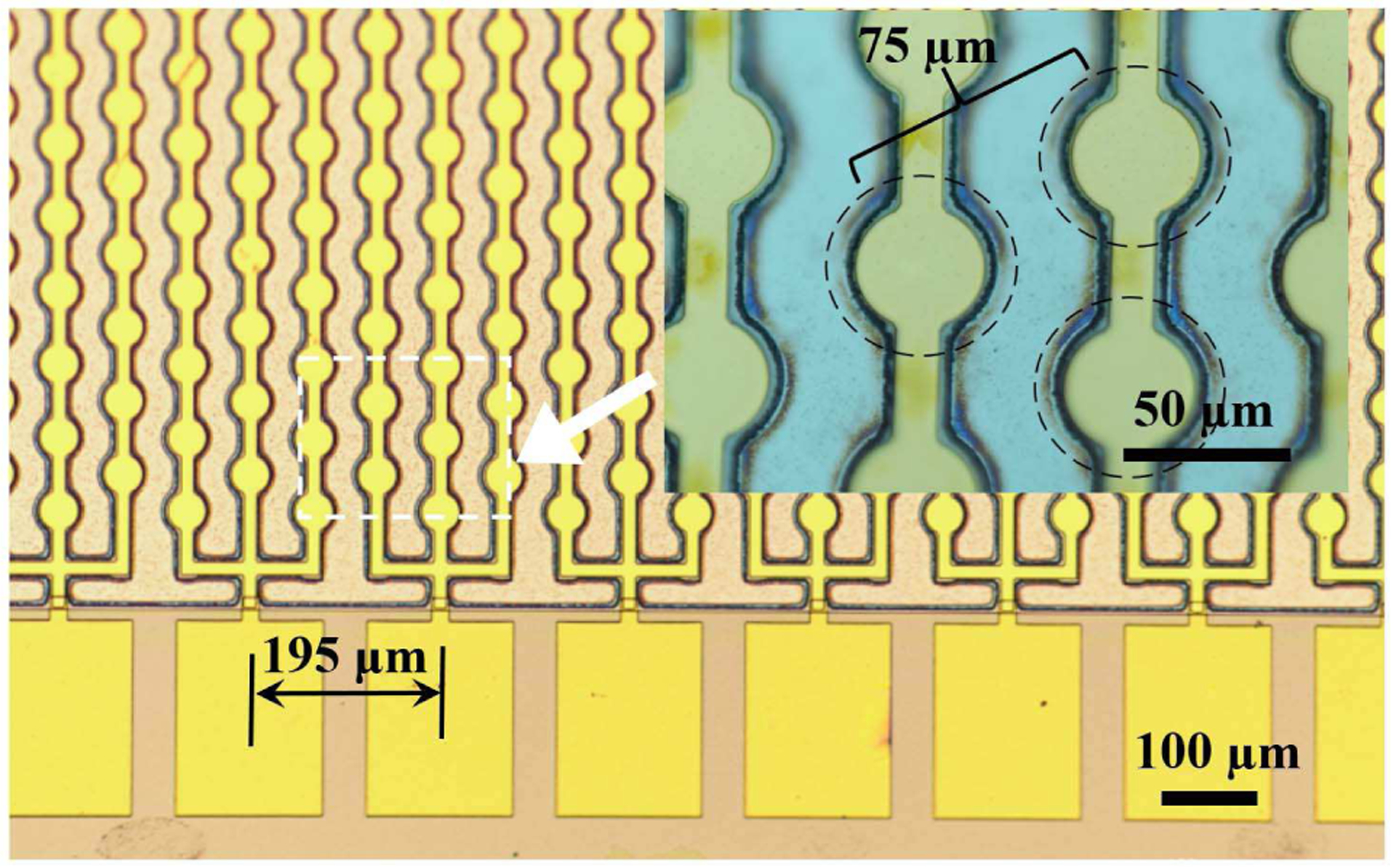
Optical image of a linear 65-element PMUT array with each element consisting of 60 diaphragms. The inset shows the center-to-center distance between individual hexagonally packed PMUT diaphragms; the dashed circles denote the suspended membranes.
The fabrication process started with a silicon on insulator (SOI) wafer with a 2 μm thick Si device layer and 2 μm thick buried thermal oxide layer (Ultrasil Corporation, Hayward, California, USA). Wet oxidation was used to grow an SiO2 layer of ~ 0.16 μm thickness. Then, 30 nm thick Ti was sputtered on the device layer side followed by rapid thermal annealing with 10 sccm of oxygen flow for 15 minutes at 700◦C and sputtering of 100 nm of Pt at > 500◦C, as described elsewhere [49]. In order to achieve highly {001} oriented PZT films, first a seed layer was deposited by spinning a solution of Pb(Zr0.52Ti0.48) O3 doped with 2% Nb with 20 mole percent excess lead (Mitsubishi Materials Corporation, Hyogo, Japan) at 6000 RPM for 30 sec. The seed layer was then pyrolyzed at 200◦C for 150 sec before crystallization via rapid thermal annealing in a lead-rich environment at 700◦C for 1 min. The film was then spun using 14 mole percent lead excess solution to achieve a Pb(Zr0.52Ti0.48) O3 film doped with 2% Nb (Mitsubishi Materials Corporation, Hyogo, Japan) at 2750 RPM for 45 sec. The film was then pyrolyzed at 100◦C for 1 min and 300◦C for 4 min, followed by crystallization in a lead-rich rapid thermal annealer for 1 min at 700 ◦C. This process was repeated 20 times until a total thickness of 1.9 μm was achieved. A thin layer of 0.08 M PbO solution was spun at 6000 RPM for 45 sec with the same pyrolysis and crystallization steps as the aforementioned 20 PZT layers to avoid any pyrochlore phase formation at the top surface of the PZT layer [11]. 2 nm of Ti was then sputtered as an adhesion layer followed by 50 nm of Pt without breaking vacuum for the top electrode. The electrodes were patterned via liftoff, then annealed at 600◦C in oxygen for one minute to improve the electrode/dielectric interface. Then 500 nm of Au was deposited using another set of sputtering and liftoff steps on the top electrode to reduce its resistance. Areas not covered by the top electrode were ion milled to gain access to the bottom electrode. Afterwards, a 0.9 μm thick bis (benzocyclobutene, BCB) layer was spun and cured as an insulation layer to reduce parasitic capacitance associated with the fan out and bonding pads. The bond pad metallization was 20 nm Ti and 500 nm Au, sputtered without breaking vacuum, and patterned by lift-off. The diaphragms were released via deep reactive ion etching (DRIE) of the handle silicon layer from the back of the wafer. The wafer consisting of fabricated PMUT arrays was diced into individual PMUT arrays using a dicing saw. The diced PMUT arrays were characterized and used in the development of the PAI device.
B. PAI device design and integration
As shown in Fig. 2, a PAI device was developed by tightly integrating a custom made fused silica-silica fiber bundle of 2-meter length (Fiberoptics Systems, Simi Valley, California, USA) and a custom-designed PCB bonded to a linear PMUT array. To start with, an individual PMUT array die was mounted on the PCB with silver paint. The PMUT array was then wire bonded to the PCB and conformally coated with ~4 μm of parylene for waterproofing. The PCB-PMUT assembly was then fixed to the flat surface of the distal (light output) end of the fiber bundle that emits light into the targeted imaging region from two rectangular optical windows of 1.5 mm wide and 30 mm long dimensions, with a ~10 mm gap in between the windows to provide dark-field illumination. The distal end of the fiber bundle, consisting of PCB-PMUT assembly at the center of the two optical windows, is further housed inside a semi-cylindrical acrylic housing to facilitate transrectal photoacoustic human prostate imaging applications in future. The proximal (input) end of the fiber bundle assembly is connected directly to a wavelength tunable OPO laser (Phocus Mobile, Opotek Inc., Carlsbad, CA, USA), for photoacoustic imaging experiments.
Fig. 2.
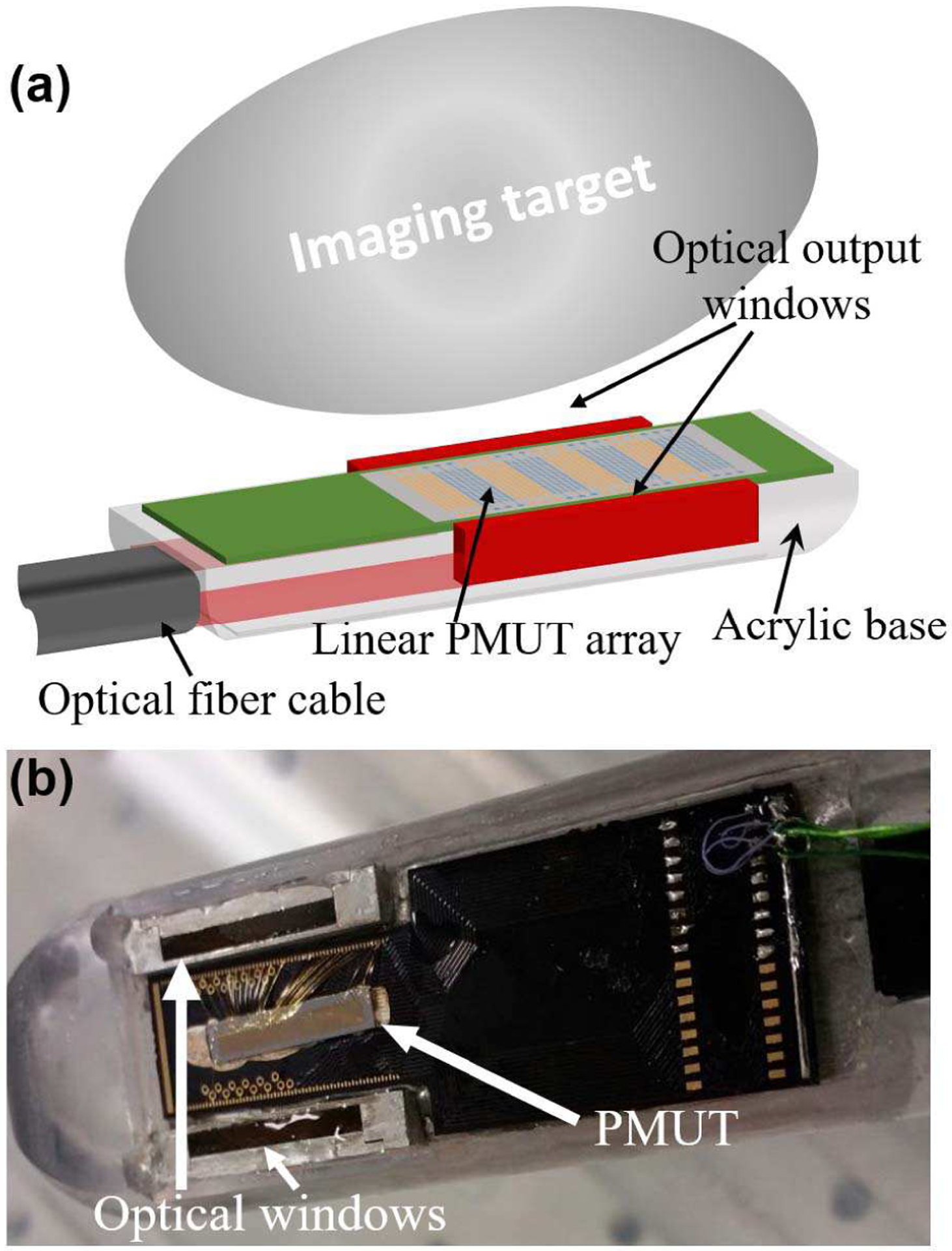
(a) A schematic representation of the PMUT based photoacoustic imaging probe showing the integration of the linear PMUT array with the optical fiber bundles fused to produce two rectangular windows illuminating the imaging target. (b) A picture of the PMUT array wire-bonded to a PCB and integrated into the light guide apparatus.
C. Material characterization
X-ray diffraction (XRD) and field-emission electron microscopy (FESEM) were used to evaluate the structural quality of the PZT film, while permittivity and hysteresis loops were taken to evaluate the low and high field dielectric properties. The results are shown in Fig. 3. It can be seen that highly {100} oriented, phase-pure perovskite PZT was achieved. An average permittivity of 1490 and mean loss tangent of 1.3% were observed at 1 kHz, with element-to-element standard deviations of 18 and 0.1% respectively. Hysteresis loops indicate a remnant polarization of ~21 μm/cm2 and a coercive field of ~50 kV/cm.
Fig. 3.
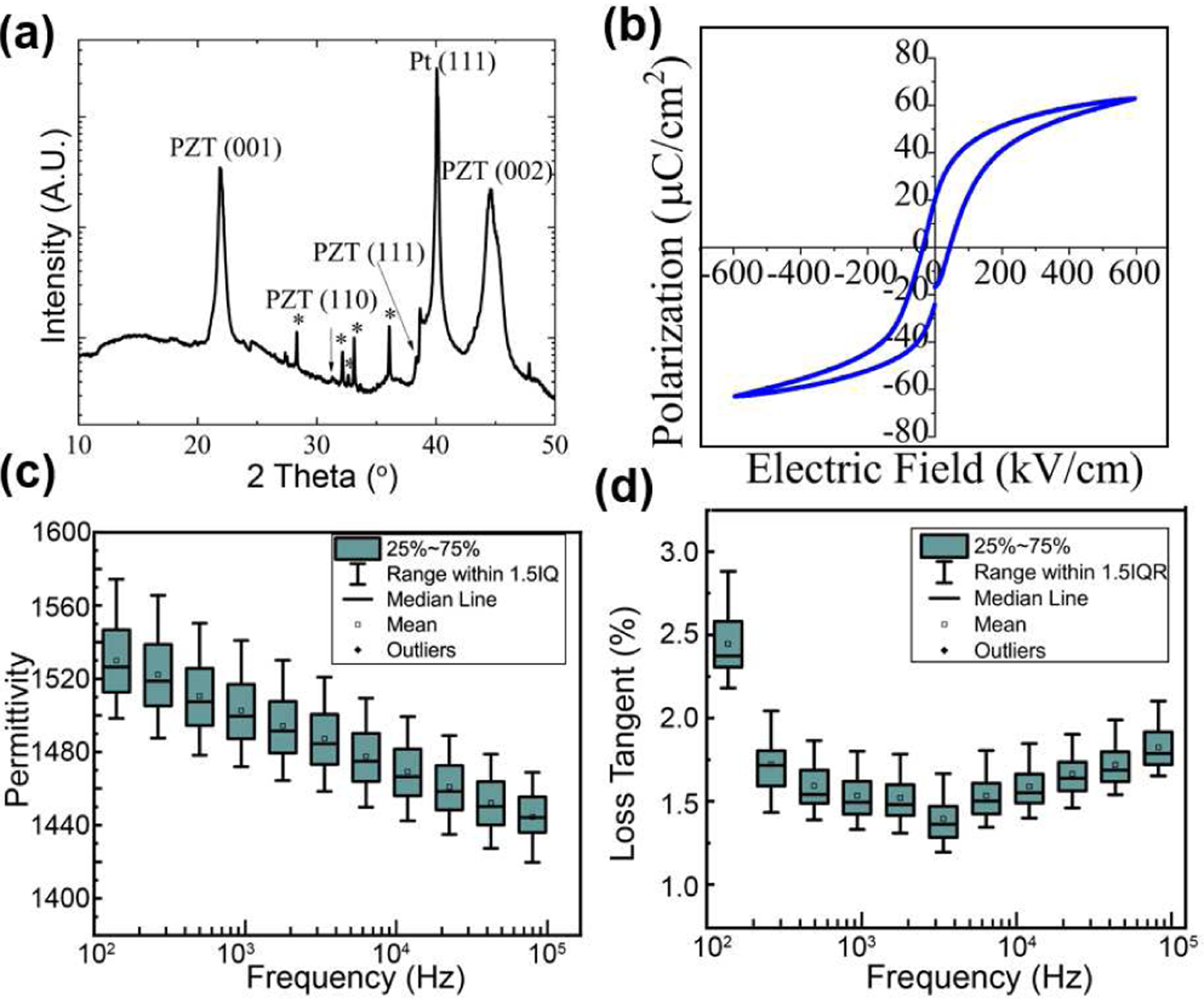
Evaluation of the PZT via (a) XRD, and (b) hysteresis loops. Measurements of (c) permittivity and (d) loss tangent of the thin film PZT for multiple elements on the PMUT device. Both permittivity and loss tangent showed less than 10% variation, for 20 different elements on the same die.
D. PMUT Vibration and Acoustic Characterization
The PMUT cells were characterized for in-air resonance using a Laser Doppler Vibrometer (LDV) (MSA-500, Polytec GmbH, Waldbronn, Germany). When actuated in air, the first mode resonance was found to lie between 6.0 MHz and 8.0 MHz for PMUTs taken from across the wafer. These variations in the first mode resonant frequencies were attributed to variations in the diaphragm size caused by footing from the DRIE process. The frequency range within a die was narrow. A frequency sweep near the resonance for in-air vibrations gives a deflection sensitivity of ~55 nm/V at the center of a PMUT diaphragm. Higher harmonics were seen near 13.0 and 19.5 MHz, as shown in Fig. 4.
Fig. 4.
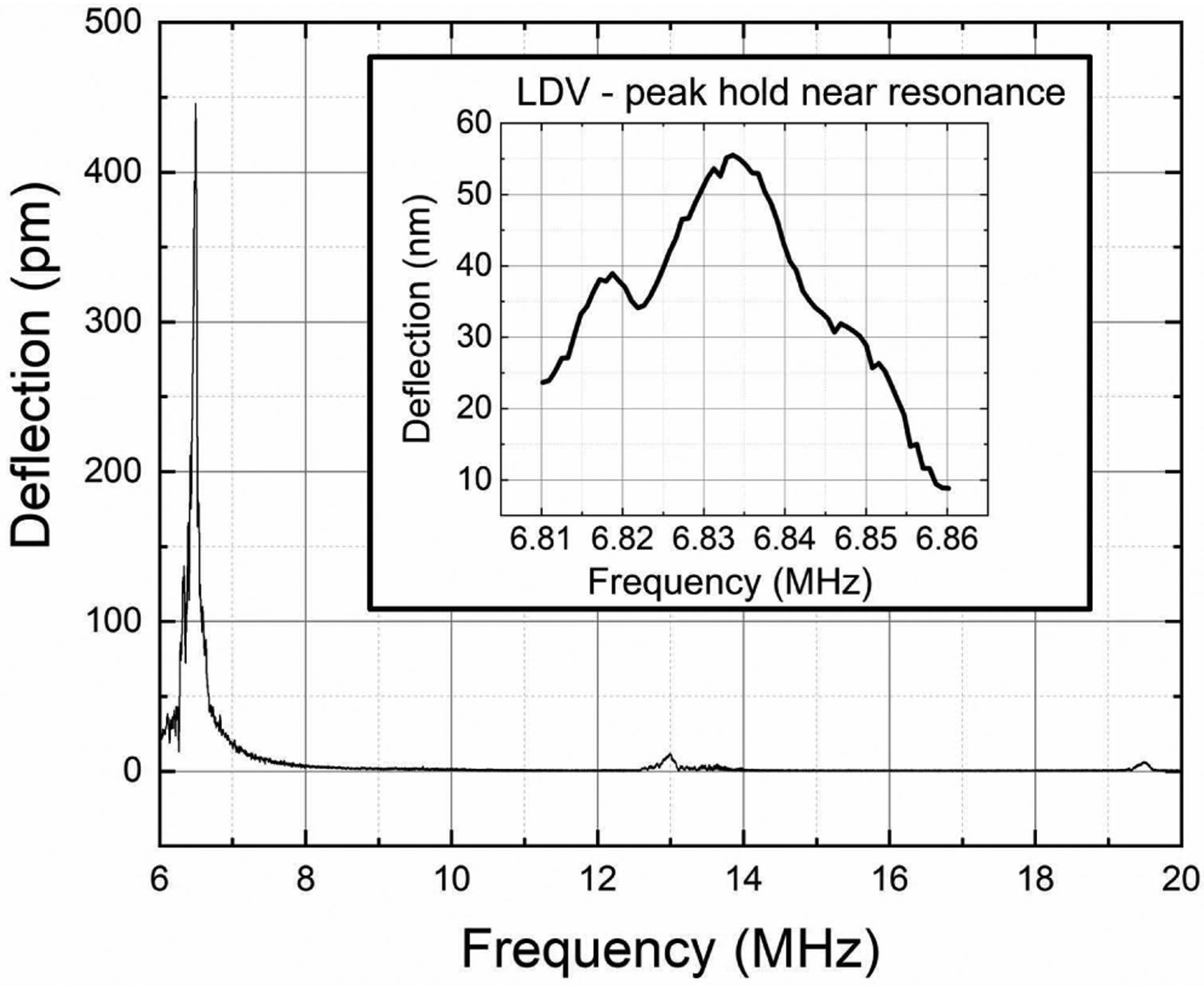
In-air chirp excitation measurements using laser Doppler vibrometry from a PMUT array element show a first resonant peak between 6.0 MHz and 8.0 MHz. Higher modes can also be seen at ~13.0 MHz and ~19.5 MHz. The inset shows the peak-hold measurements around the first peak, giving ~55 nm/V deflection sensitivity for the PMUT at resonance.
For acoustic characterization, pressure outputs were obtained from 12 different elements of a linear array, with each element having 60 diaphragms. The pressure output for each element was measured by placing the PMUT in an acrylic water-tank and operating the PMUT in transmit mode while a wideband hydrophone (HGL-0085, Onda Corp., Sunnyvale, CA, USA) acted as a receiver at 7.5 mm distance from the surface of the transducer. The elements were poled at 15 V for 15 minutes at room temperature prior to the experiments. One element was excited with a unipolar 5 Vpp signal at resonance in a 5-cycle sinusoidal burst mode. The results are shown in Fig. 5. The output pressure recorded from 12 different elements shows on an average 16.2 kPa output with 0.96 kPa standard deviation.
Fig. 5.
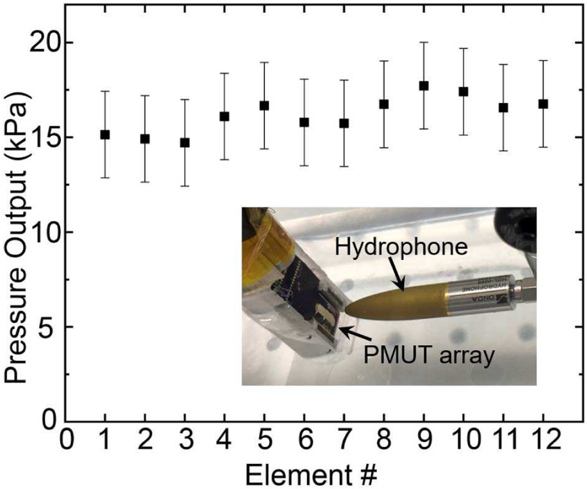
Pressure output for 12 different PMUT elements in the array at 7.5 mm from the PMUT surface, with each element containing 60 diaphragms excited using a 5 Vpp unipolar input. The inset shows the experimental setup, with the hydrophone ~7.5 mm distance away from the PMUT.
E. Receive sensitivity measurements
Another critical figure-of-merit of ultrasound transducers for photoacoustic imaging applications is the receive sensitivity. To characterize the receive sensitivity of the PMUT, a 0.5 inch diameter single element bulk ultrasound transducer with 8 MHz center frequency was used as the acoustic source (transmitter). The bulk ultrasound transducer was excited using one cycle of 5 Vpp sinusoidal pulse of 8 MHz frequency, generated by an arbitrary waveform generator (SDG6022X, Siglent Technologies, Solon, OH, USA). The ultrasound pressure at 26 mm distance from the transmitter is detected first by different elements of the PMUT array and then using the calibrated hydrophone. Both the PMUT array and the hydrophone were aligned along the longitudinal axis of the transmitter for these measurements. The output of the PMUT was amplified with 18 dB gain using a preamplifier (5073PR, Olympus NDT Inc, Waltham, MA, USA), and the resulting voltage signal was captured using an oscilloscope (MDO3024, Tektronix, Beaverton, OR, USA). Fig. 6(a) shows the voltage output of the PMUT averaged over eight acquisitions giving ~65 mV peak-to-peak voltage output. Fig. 6(b) shows the voltage output recorded by the hydrophone, which corresponds to ~17 kPa peak-to-peak pressure output. The receive sensitivity of the PMUT, estimated by dividing the peak-to-peak voltage output of the PMUT element by the peak-to-peak pressure measured by the hydrophone, was found to be ~0.48 mV/kPa with 0 dB gain.
Fig. 6.
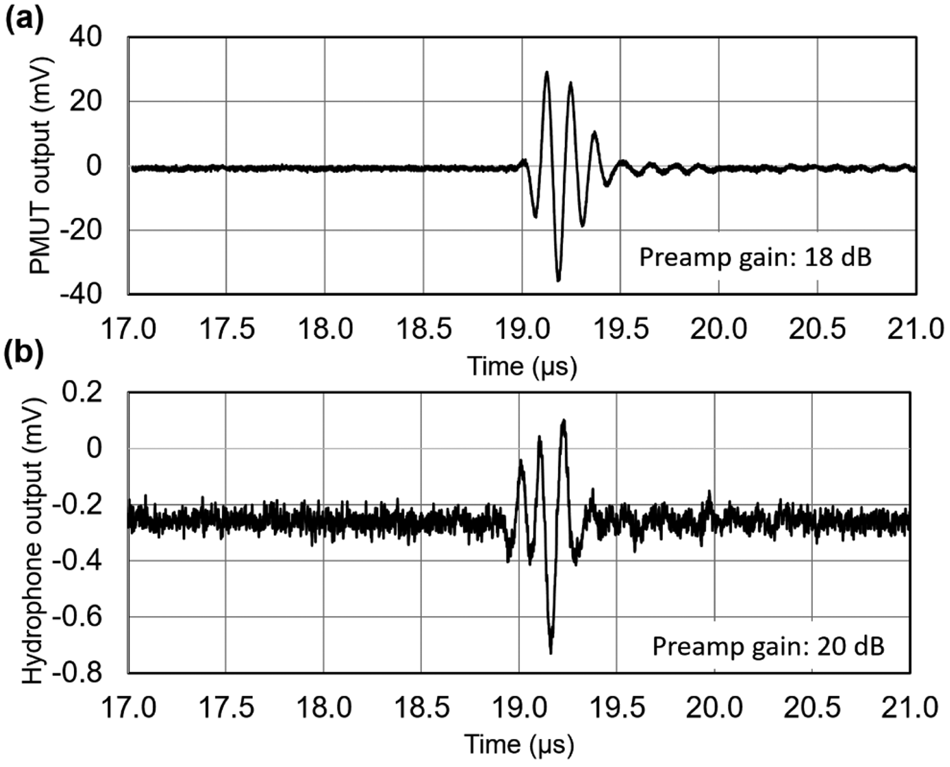
Receive sensitivity measurements: (a) Voltage output of a PMUT element when excited by a bulk ultrasound transmitter placed 26 mm away and actuated by a single sinusoidal pulse input. (b) Voltage output of a calibrated hydrophone captured at the same location as that of the PMUT measurement.
III. PHOTOACOUSTIC IMAGING
A. Experimental setup for photoacoustic imaging
A 32 cm × 18 cm × 12 cm, plastic tank, filled with de-ionized water was used for the photoacoustic imaging experiments. Phantoms to be imaged were placed at the bottom of the tank; the entire PAI device was submerged with the PMUT array and light output facing the phantom. The distal end of the PAI device was fixed to a motorized 3-axis linear stage (NRT100, Thorlabs, Newton, NJ, USA) for alignment. The light pulses (from the laser) propagate through the imaging phantom and are absorbed by chromophores in the phantom, subsequently generating broadband photoacoustic pressure waves due to transient thermoelastic expansion. The generated photoacoustic pressure is sensed by the PMUT array. In the current experiments, the laser provides a maximum fluence of ~10 mJ/ cm2 at 800 nm at the output end of the fiber bundle, which is well within the ANSI safety limits [50]. The voltage output from a single PMUT array element was connected to a commercial preamplifier (5073PR, Olympus NDT Inc, Waltham, MA, USA) providing 39 dB gain. The pre amplified output was digitized using a 16-bit data acquisition card (Gage RazorMax16, Dynamic Signals LLC, Lockport, IL, USA) at 1 GSPS in synchronization with each laser pulse.
B-mode photoacoustic imaging requires the ultrasound signals generated by the phantom to be captured by a linear array of ultrasonic receivers with typically 128 or 256 evenly spaced elements. The data acquisition system used for current experiments was limited to four channels. Thus, a linear array acquisition was emulated by linearly scanning the PAI device to 300 to 500 positions, depending on the size of the phantom, along the length of the device with a 100 μm step size, while the phantom was kept undisturbed. The raw photoacoustic A-line data captured at these positions mimics imaging with linear array with 100 μm element pitch. The position control of the device was achieved using the linear stage while Matlab (Mathworks Inc., Natick, MA, USA) based control software was used to control the data acquisition and the motion of the linear stage. 20 A-line signals were averaged at each spot in order to reduce the noise floor.
B. Phantom preparation
The device was tested for photoacoustic imaging capabilities using tissue-mimicking phantoms. First, an agar-gel phantom was prepared by mixing 1.5 grams of agarose in 100 ml of de-ionized water. The solution was heated for 2 minutes in a standard kitchen microwave. Before solidification, a portion of the solution was poured in a rectangular box, creating a 5-mm thick bed. The base agar-gel pad thus formed was allowed to settle by cooling in a refrigerator for 5 minutes. One pencil lead with 0.3 mm diameter was placed on the bed and another ~5 mm thick layer of agar-gel was poured on top. The process was repeated for 6 layers, resulting in an agar-gel phantom with six pencil-leads placed in diagonal pattern along the depth between 4 mm to 20 mm depth (see Fig. 8(a)). The agar-gel phantom was then placed underwater along with the PMUT. The distance between the PAI device and the top surface of the agar-gel phantom was ~10 mm.
Fig. 8.
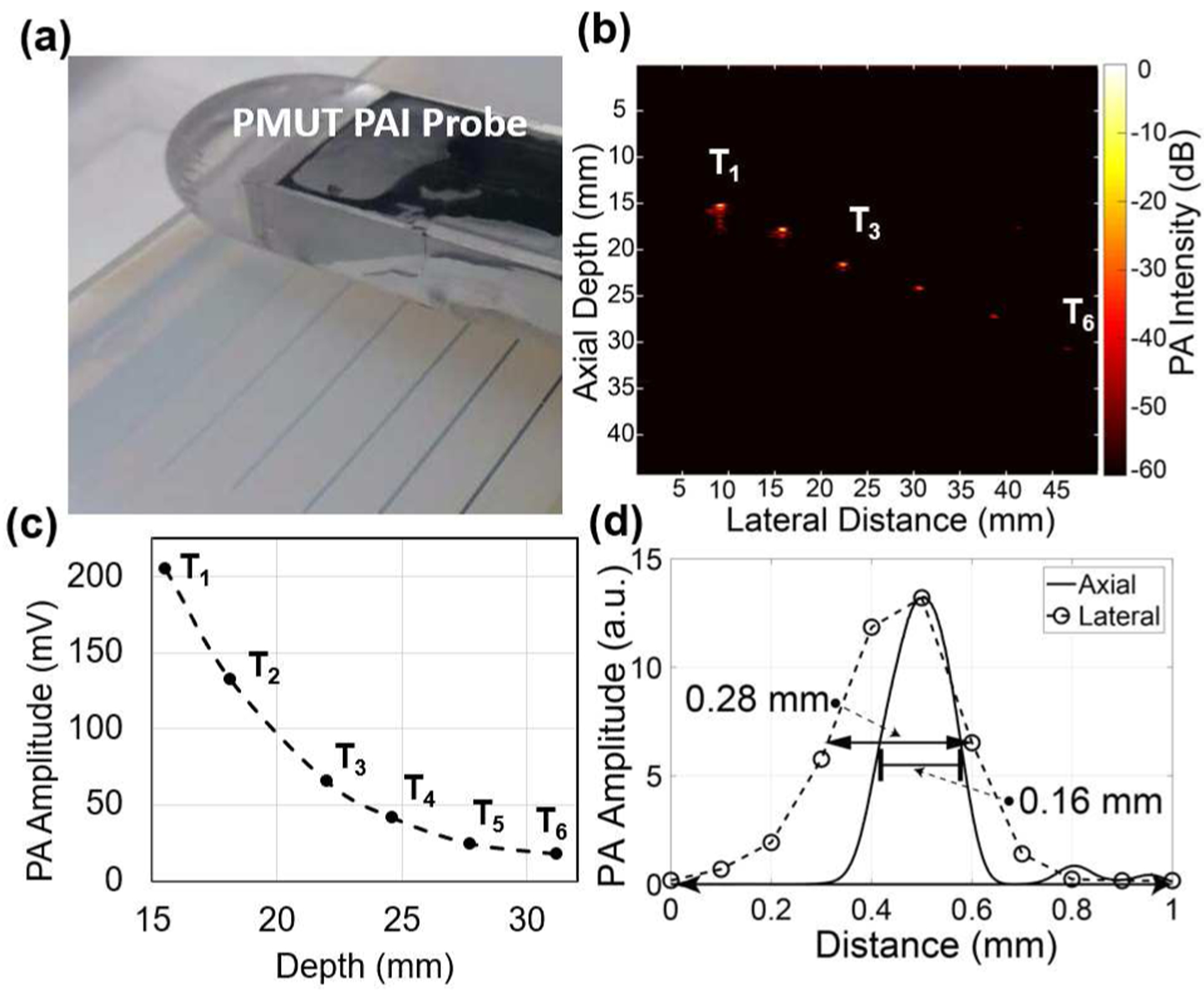
B-mode photoacoustic imaging of six pencil-leads embedded inside agar-gel: (a) Experimental setup showing the agar-gel phantom with six pencil leads at various depths and the PAI device facing the phantom. (b) B-mode photoacoustic image obtained by frequency domain reconstruction over a 50 mm range with 0.1 mm pitch shows all six pencil leads. (c) The intensity of the photoacoustic signals from the pencil leads reduces as a function of depth inside the phantom. (d) Lateral imaging resolution estimated from the full width at half maximum (FWHM) of the peak intensity at the center of the pencil lead and the axial resolution determined from an envelope function fitted over the PA pulse from the pencil lead.
C. Photoacoustic characterization and imaging of tissue phantoms
A single A-line signal captured from a pencil lead embedded in agar-gel and aligned for maximum photoacoustic output is shown in Fig. 7. The photoacoustic pulse, received ~23.5 μs after the laser excitation, matched with the pencil lead at ~36 mm distance from the PMUT array element and showed ~350 mVpp pulse amplitude. Using this single A-line signal, the frequency response of the photoacoustic pulse was found to be ~6.75 MHz center frequency with ~89% bandwidth.
Fig. 7.
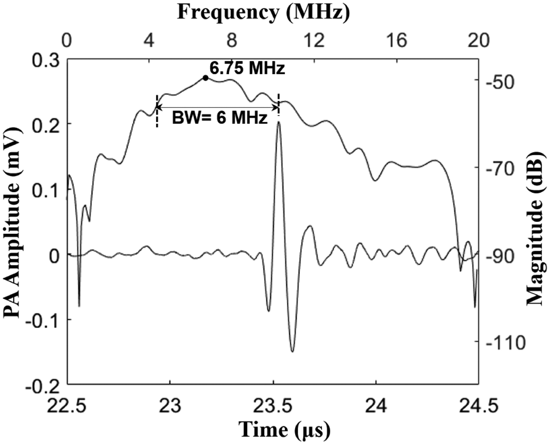
Photoacoustic signal captured from a pencil lead target shows ~320 mV peak-to-peak amplitude, after 39 dB gain at the preamplifier stage. The frequency response of the photoacoustic pulse shows a ~6.75 MHz center frequency with ~89% bandwidth.
Using the PAI device, the agar-gel phantom with 6 embedded pencil leads was imaged (see Fig. 8(a)). A Fourier transform based algorithm was used to reconstruct B-mode images from the raw voltage-time data [11]. Figure 8(b) shows the reconstructed B-mode photoacoustic image from the 500 signals captured by the PMUT array element while scanning the device over 5 cm with a 0.1 mm pitch. The first four pencil leads, identified as T1 to T4, were clearly visible. The last two pencil leads T5 and T6 were barely visible in the reconstructed PAI image. No time gain compensation was used in the reconstruction algorithm; hence, the reconstructed image is expected to show a depth dependent decay in the photoacoustic contrast. As expected, a decrease in photoacoustic signal strength as a function of depth of the pencil lead can be seen from the plot in Fig. 8(c). Furthermore, the lateral and axial resolutions were estimated from the full-width at half-maximum (FWHM) of the photoacoustic amplitude of a pencil lead target, T1, plotted along the horizontal and vertical axis as shown in Fig. 8(d). The lateral and axial FWHM for T1 were found to be ~0.30 mm and ~0.15 mm respectively. The lateral FWHM was found to increase with depth, reaching up to 0.57 mm for the sixth pencil lead.
Additional photoacoustic imaging experiments were conducted for the four different conditions shown in Fig. 9(a–d). Firstly, Fig. 9(a) shows an agar gel phantom with a polyethylene tube having 1.09 mm outer diameter and 0.38 mm inner diameter filled with a 200 μM indocyanine green (ICG) solution, embedded inside the agar-gel. When the submerged PAI-PMUT probe was aligned directly above the ICG tube phantom, at a ~20 mm gap, a photoacoustic output of ~80 mVpp was captured.
Fig. 9.
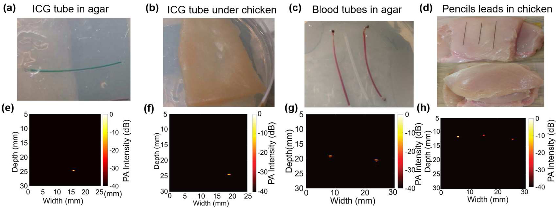
B-mode photoacoustic imaging (PAI): (a) A clear agar-gel phantom with an ICG-filled tube as target. (b) Phantom shown in (a) is covered with 2 mm thick chicken tissue layer to introduce scattering of the light. (c) A clear agar-gel phantom with two blood filled polymer tubes embedded at 5 mm depth with an unfilled tube placed between the two tubes. (d) Pictures showing the preparation of chicken tissue-based phantom. Three 0.3 mm pencil leads were placed on the chicken bed and then an 8 mm thick chicken tissue layer was placed on top of the pencil leads. (e), (f), (g), and (h) are the reconstructed B-mode (photoacoustic images from phantoms shown in (a), (b), (c), and (d) respectively. The color-bar for all the reconstructed images represents the photoacoustic intensity, normalized with respect to the maxima within each image, on log scale with 0 dB to Š40 dB range. All images were acquired using linear scanning of single element PMUT with 0.1 mm step size.
Secondly, the agar-gel phantom with the ICG-filled tube was covered with ~3 mm of chicken tissue as shown in Fig. 9(b) to induce scattering in the optical illumination. While the photoacoustic signal decreased (the amplitude of the photoacoustic pulse was reduced to ~30 mVpp), the ICG filled tube was imaged clearly at ~25 mm distance from the PMUT-PAI device (Fig. 9(f)).
Thirdly, an imaging phantom consisting of two bovine blood (905–100, Quad Five Inc., Ryegate, MT, USA) filled polyethylene tubes, separated by a clear tube, all of which were embedded in agar-gel as shown in Fig. 9(c), was investigated as a target. As shown in the reconstructed image in Fig. 9(g), the two blood-filled tubes were detected, while the tube without blood did not generate any above-noise photoacoustic signal due to the lack of absorption.
Finally, the fourth demonstration consisted of imaging pencil lead targets embedded under 8 mm of chicken tissue (Fig. 9(d,h)). An ~8 mm thick slice of chicken tissue was used as the bed on which three 0.3 mm pencil leads were placed with ~15 mm separation, and another ~8 mm thick chicken slice was placed on the top. Care was taken to minimize any air gap between the layers of chicken tissues and the pencil leads. As shown in the reconstructed photoacoustic image in Fig. 9(h), the three pencil leads could be detected through 8 mm of chicken tissue. For the three pencil leads under chicken, the axial resolutions lie between 0.16 mm to 0.18 mm and the lateral resolutions lie between 0.30 mm to 0.50 mm, as estimated using the approach described for Fig 8(d).
Although the above photoacoustic imaging results with the PMUT arrays are encouraging, reducing the noise floor of the PMUTs will improve their photoacoustic sensitivity. Potential sources of noise include cross-coupling between neighboring elements, pressure induced surface and bulk acoustic waves in the PMUT substrate, the high capacitance of the PMUT element that increases the electrical noise, and the parasitic capacitance introduced by wires connecting the PMUT elements to the imaging system. These noise sources can be reduced by techniques such as introduction of trenches around the PMUT elements to attenuate substrate vibrations and cross coupling or using lower permittivity materials. Secondly, it is observed that the receive sensitivity of the PMUT element can vary depending on the poling conditions. The PZT thin film may depole when excited using high voltage (>5V) sinusoidal input or when exposed to excessive heat. Hence, it is necessary to ensure uniform poling of the PZT thin film and avoid depoling. Furthermore, delamination was observed between the parylene layer and the top surface of the PMUT diaphragms for a few cases during the poling process or transmit mode operation after repeated use. Such delamination was found to cause sudden degradation in the performance of the PMUT element and needs to be studied further.
IV. CONCLUSIONS
Successful fabrication and characterization results of a ~7 MHz linear PMUT array with 89% photoacoustic bandwidth was presented. A compact handheld photoacoustic imaging device was developed by wire-bonding the array to a printed circuit board and further integrating it with a fiber optic light guide. Photoacoustic imaging experiments on different tissue phantoms established the feasibility of imaging photoacoustic contrast from blood, ICG and pencil leads through scattering tissue using PMUT arrays. These results show, for the first time, the feasibility of a PMUT-based handheld photoacoustic imaging device for imaging targets inside optically and acoustically scattering tissue. Future improvements can be achieved by using ASICs for pre-amplification and signal conditioning. Also, more complex architectures, such as PMUTs with curved or dome shaped membranes, can enable higher sensitivities [51], [52]. Low voltage (< 10V) operation, high receive sensitivity, ease of impedance match with conventional ultrasound preamplifiers and ease of fabrication of miniaturized PMUTs of various shapes and sizes make them attractive for developing multi-scale and multimode photoacoustic imaging systems.
Acknowledgments
This work was supported by the National Institute of Biomedical Imaging and Bioengineering (NIBIB), National Institute of Health (NIH), U.S. under Grant R00EB017729–04 (SRK).
Christopher Cheng was supported by the Department of Defense (DoD) through the National Defense Science & Engineering Graduate Fellowship (NDSEG) Program. Cheng and Trolier-McKinstry gratefully acknowledge funding from The Center for Nanoscale Science, a Materials Research Science and Engineering Center (MRSEC) supported by the National Science Foundation under grant DMR-1420620.
Biographies
Ajay Dangi received his B. Tech. in Mechanical Engineering from the Indian Institute of Technology, Varanasi, in 2010. He completed his Ph.D. degree in mechanical engineering in 2016 from the Indian Institute of Science, Bangalore. From 2016 to 2017, he was a research assistant in the MEMS lab at the Center for Nano Science and Engineering at the Indian Institute of Science, Bangalore. Since 2017, he has been working as a postdoctoral scholar in the Department of Biomedical Engineering at the Pennsylvania State University. His research interests include photoacoustic and ultrasound imaging, MEMS/MOEMS sensors, PMUTs, and acoustics.

Christopher Y. Cheng received his B.S. in Materials Science and Engineering and B.S. in Chemistry at the University of Minnesota, Twin Cities in 2016, graduating with cum laude. He has also interned at 3M company and the U.S. Army Research Laboratory. He is a National Science Foundation Graduate Research Fellow Awardee and a National Defense Science & Engineering Graduate Fellow. He is currently pursuing a Ph.D. degree in Materials Science and Engineering at the Pennsylvania State University, with a research focus on piezoelectric micromachined ultrasound transducers (PMUTs) and their applications.

Sumit Agrawal received a B. Tech degree in Electronics and Communication in 2012 from GLA Institute, Mathura (India) and an M. Tech in Media and Sound Engineering from I.I.T. Kharagpur, India in 2014. He then worked for a year in KLA Tencor where he explored image-processing algorithms for defect inspection in silicon wafers during IC fabrication. He later joined SkinCurate Research, India, a smart medical imaging devices startup, where he developed interest in medical imaging and machine learning. Sumit joined Dr. Kothapalli’s group as a Ph.D. student in Spring 2017 and is currently focused on developing dual modality ultrasound and photoacoustic imaging hardware as well as image reconstruction software.

Sudhanshu Tiwari received his B. Tech degree in mechanical engineering from A.P.J. Abdul Kalam Technical University, Lucknow, India in 2015. He is currently a Ph.D. student at Centre for Nano Science and Engineering, Indian Institute of Science, Bangalore, India. His research interests include PiezoMEMS design, microfabrication and vibrational analysis of MEMS structures.

Gaurav Ramesh Datta received his B. Tech. degree in electrical engineering from College of Engineering Pune, an autonomous institute of Government of Maharashtra affiliated to Savitribai Phule Pune University in 2016. Since 2017, he is enrolled at Pennsylvania State University, University Park, Pennsylvania pursuing M.S. degree. He has been working as a research assistant in the Biophotonics and Ultrasound Imaging Lab at Pennsylvania State University since May 2018.

Robert R. Benoit is an electronics engineer in the Microdevices Devices Branch of the US Army Research Laboratory (ARL), Adelphi, MD. He received his B.A. in Physics and Math from Lycoming College (2004) and completed his M.S. (2007) and Ph.D. (2014) at the University of Virginia. At UVA he studied rapid prototyping of MEMS devices with focused ion beams and cryogenic radio frequency microelectromechanical systems (RF MEMS) for radio astronomy applications. His current research involves piezoelectric RF MEMS and wafer-scale vacuum packaging techniques. Dr. Benoit is a member of IEEE and currently chairs the Washington DC/Northern VA Chapter of the Microwave Theory and Technique Society.

Rudra Pratap graduated with a BTech (Hons.) degree from IIT Kharagpur, India, in 1985; M.S. degree from the University of Arizona, Tucson, USA in 1987 and Ph.D. from Cornell University in 1993. He taught in the Sibley School of Mechanical & Aerospace Engineering at Cornell University during 1994–1996. He then joined the Department of Mechanical Engineering at the Indian Institute of Science, Bangalore, as an Assistant Professor in 1996 and served there full time from 1996 – 2010. He moved to the Centre for Nano Science and Engineering (CeNSE) as a Professor and the Founding Chairperson. He continues as an associate faculty of Mechanical Engineering. He is currently serving as the Deputy Director of the Indian Institute of Science since August 2018. His research interests include MEMS and NEMS, vibroacoustics, bioacoustics, mechano-biology, and computational mechanics. He is an Associate Editor of IEEE/ASME Journal of MEMS and Journal of ISSS. He is an elected Fellow of the National Academy of Engineering and National Academy of Science.

Susan Trolier-McKinstry is the Steward S. Flaschen Professor of Ceramic Science and Engineering, Professor of Electrical Engineering, and Director of the Nanofabrication facility at the Pennsylvania State University. Her main research interests include thin films for dielectric and piezoelectric applications, and she has written ~400 papers on those topics. She currently serves as an associate editor for Applied Physics Letters. She was 2017 President of the Materials Research Society; previously she served as president of the IEEE Ultrasonics, Ferroelectrics and Frequency Control Society, as well as Keramos. She is an elected member of the National Academy of Engineering (NAE).

Sri-Rajasekhar Kothapalli received his Ph.D. in Biomedical Engineering from the Washington University in Saint Louis in 2009. After that, he carried out his postdoctoral research from 2009 to 2013 at Stanford University. From 2014–2016, he served as an instructor in the Department of Radiology, Stanford University. His research work spans various biomedical imaging techniques including photoacoustic imaging, ultrasound imaging, and ultrasound-modulated optical tomography (UOT). Working at the interface of MEMS ultrasound transducer and photoacoustic imaging, he developed CMUT based dual modality transrectal ultrasound and photoacoustic (TRUSPA) imaging device for prostate cancer screening, and conducted clinical studies on several prostate cancer patients using the TRUSPA device. He is currently an assistant professor in the department of biomedical engineering at the Pennsylvania State University, State College.

Contributor Information
Ajay Dangi, the Department of Biomedical Engineering, Pennsylvania State University, University Park, PA, USA..
Christopher Cheng, the Department of Materials Science and Engineering and Materials Research Institute, Pennsylvania State University, University Park, PA, USA..
Sumit Agrawal, the Department of Biomedical Engineering, Pennsylvania State University, University Park, PA, USA..
Sudhanshu Tiwari, the Centre for Nano Science and Engineering, Indian Institute of Science, Bangalore, India..
Gaurav Ramesh Datta, the Department of Electrical Engineering, Pennsylvania State University, University Park, PA, USA..
Robert Benoit, the Sensors and Electron Devices Directorate, Army Research Lab, Adelphi, MD, USA..
Rudra Pratap, the Centre for Nano Science and Engineering, Indian Institute of Science, Bangalore, India..
Susan Trolier-McKinstry, the Department of Materials Science and Engineering and Materials Research Institute, Pennsylvania State University, University Park, PA, USA..
Sri-Rajasekhar Kothapalli, the Department of Biomedical Engineering, Pennsylvania State University, University Park, PA, USA and Penn State Cancer Institute, Pennsylvania State University, Hershey, PA, USA..
REFERENCES
- [1].Beard P, “Biomedical photoacoustic imaging,” Interface Focus, vol. 1, no. 4, pp. 602–631, 2011. [DOI] [PMC free article] [PubMed] [Google Scholar]
- [2].Xu M and Wang LV, “Photoacoustic imaging in biomedicine,” Review of Scientific Instruments, vol. 77, no. 4 2006. [Google Scholar]
- [3].Xiang L, Wang B, Ji L, and Jiang H, “4-D Photoacoustic Tomography,” Sci. Rep, vol. 3, no. 1, p. 1113, Dec. 2013. [DOI] [PMC free article] [PubMed] [Google Scholar]
- [4].Valluru KS and Willmann JK, “Clinical photoacoustic imaging of cancer,” Ultrasonography, vol. 35, no. 4, pp. 267–280, 2016. [DOI] [PMC free article] [PubMed] [Google Scholar]
- [5].Kitai T et al. , “Photoacoustic mammography: Initial clinical results,” Breast Cancer, vol. 21, no. 2, pp. 146–153, 2014. [DOI] [PubMed] [Google Scholar]
- [6].Cox B, Laufer JG, Arridge SR, and Beard PC, “Quantitative spectroscopic photoacoustic imaging: a review,” J. Biomed. Opt, vol. 17, no. 6, p. 061202, 2012. [DOI] [PubMed] [Google Scholar]
- [7].Wang LV and Hu S, “Photoacoustic tomography: In vivo imaging from organelles to organs,” Science, vol. 335, no. 6075 pp. 1458–1462, 2012. [DOI] [PMC free article] [PubMed] [Google Scholar]
- [8].Ntziachristos V, “Going deeper than microscopy: The optical imaging frontier in biology,” Nat. Methods, vol. 7, no. 8, pp. 603–614, Aug. 2010. [DOI] [PubMed] [Google Scholar]
- [9].Wang LV, “Multiscale photoacoustic microscopy and computed tomography,” Nat. Photonics, vol. 3, no. 9, pp. 503–509, 2009. [DOI] [PMC free article] [PubMed] [Google Scholar]
- [10].Zackrisson S, Van De Ven SMWY, and Gambhir SS, “Light in and sound out: Emerging translational strategies for photoacoustic imaging,” Cancer Research, vol. 74, no. 4 2014. [DOI] [PMC free article] [PubMed] [Google Scholar]
- [11].Denis LM, Esteves G, Walker J, Jones JL, and Trolier-McKinstry S, “Thickness dependent response of domain wall motion in declamped {001} Pb(Zr0·3Ti0.7) O3 thin films,” Acta Mater, vol. 151, pp. 243– 252, Jun. 2018. [Google Scholar]
- [12].Stoffels I et al. , “Metastatic status of sentinel lymph nodes in melanoma determined noninvasively with multispectral optoacoustic imaging.,” Sci. Transl. Med, vol. 7, no. 317, p. 317ra199, 2015. [DOI] [PubMed] [Google Scholar]
- [13].Heijblom M, Steenbergen W, and Manohar S, “Clinical photoacoustic breast imaging: The twente experience,” IEEE Pulse, vol. 6, no. 3, pp. 42–46, 2015. [DOI] [PubMed] [Google Scholar]
- [14].Kothapalli SR et al. , “Human prostate imaging using a novel integrated transrectal ultrasound and photoacoustic instrument,” Mol. Imaging Biol, vol. 15, no. 1, pp. S1447–S1448, 2013. [Google Scholar]
- [15].Yaseen MA, “Optoacoustic imaging of the prostate: development toward image-guided biopsy,” J. Biomed. Opt, vol. 15, no. 2, p. 021310, 2010. [DOI] [PMC free article] [PubMed] [Google Scholar]
- [16].Kothapalli SR et al. , “Deep Tissue Photoacoustic Imaging Using a Miniaturized 2-D Capacitive Micromachined Ultrasonic Transducer Array,” IEEE Trans. Biomed. Eng, vol. 59, no. 5, pp. 1199–1204, May 2012. [DOI] [PMC free article] [PubMed] [Google Scholar]
- [17].Aguirre A, Ardeshirpour Y, Sanders MM, Brewer M, and Zhu Q, “Potential Role of Coregistered Photoacoustic and Ultrasound Imaging in Ovarian Cancer Detection and Characterization,” Transl. Oncol, vol. 4, no. 1, pp. 29–37, 2011. [DOI] [PMC free article] [PubMed] [Google Scholar]
- [18].Dima A and Ntziachristos V, “In-vivo handheld optoacoustic tomography of the human thyroid,” Photoacoustics, vol. 4, no. 2, pp. 65–69, 2016. [DOI] [PMC free article] [PubMed] [Google Scholar]
- [19].Knieling F et al. , “Multispectral Optoacoustic Tomography for Assessment of Crohn’s Disease Activity,” N. Engl. J. Med, vol. 376, no. 13, pp. 1292–1294, Mar. 2017. [DOI] [PubMed] [Google Scholar]
- [20].Jensen JA et al. , “SARUS: A synthetic aperture real-time ultrasound system,” IEEE Trans. Ultrason. Ferroelectr. Freq. Control, vol. 60, no. 9, pp. 1838–1852, Sep. 2013. [DOI] [PubMed] [Google Scholar]
- [21].Oralkan Ö et al. , “Capacitive micromachined ultrasonic transducers: Next-generation arrays for acoustic imaging?,” IEEE Trans. Ultrason. Ferroelectr. Freq. Control, vol. 49, no. 11, pp. 1596–1610, 2002. [DOI] [PubMed] [Google Scholar]
- [22].Dangi A, Hulge A, Somasundaran A, Valsalam RS, and Pratap R, “Complete development of a single cell PMUT transducer: design, fabrication, characterization, and integration,” J. Inst. Smart Struct. Syst, vol. 4, no. 41, pp. 61–69, 2015. [Google Scholar]
- [23].Demirci U, Ergun AS, Oralkan Ö, Karaman M, and Khuri Yakub BT, “Forward-viewing CMUT arrays for medical imaging,” IEEE Trans. Ultrason. Ferroelectr. Freq. Control, vol. 51, no. 7, pp. 887–895, 2004. [DOI] [PubMed] [Google Scholar]
- [24].Jiang X et al. , “Ultrasonic fingerprint sensor with transmit beamforming based on a PMUT array bonded to CMOS circuitry,” IEEE Trans. Ultrason. Ferroelectr. Freq. Control, vol. 64, no. 9, pp. 1401–1408, 2017. [DOI] [PubMed] [Google Scholar]
- [25].Oralkan Ö et al. , “Experimental characterization of collapse-mode CMUT operation,” IEEE Trans. Ultrason. Ferroelectr. Freq. Control, vol. 53, no. 8, pp. 1513–1523, 2006. [DOI] [PubMed] [Google Scholar]
- [26].Chee R, Sampaleanu A, Rishi D, and Zemp R, “Top orthogonal to bottom electrode (TOBE) 2-D CMUT arrays for 3-D photoacoustic imaging,” IEEE Trans. Ultrason. Ferroelectr. Freq. Control, vol. 61, no. 8, pp. 1393–1395, 2014. [DOI] [PubMed] [Google Scholar]
- [27].Greenlay BA and Zemp RJ, “Fabrication of linear array and top-orthogonal-to-bottom electrode CMUT arrays with a sacrificial release process,” IEEE Trans. Ultrason. Ferroelectr. Freq. Control, vol. 64, no. 1, pp. 93–107, 2017. [DOI] [PubMed] [Google Scholar]
- [28].Oralkan Ö et al. , “Volumetric ultrasound imaging using 2-D CMUT arrays,” IEEE Trans. Ultrason. Ferroelectr. Freq. Control, vol. 50, no. 11, pp. 1581–1594, 2003. [DOI] [PubMed] [Google Scholar]
- [29].Zahorian J et al. , “Monolithic CMUT-on-CMOS integration for intravascular ultrasound applications,” IEEE Trans. Ultrason. Ferro- electr. Freq. Control, vol. 58, no. 12, pp. 2659–2667, 2011. [DOI] [PMC free article] [PubMed] [Google Scholar]
- [30].Kshirsagar A et al. , “Multi-frequency CMUT arrays for imaging therapy applications,” in IEEE International Ultrasonics Symposium (IUS), Prague, 2013, pp. 1991–1993. [Google Scholar]
- [31].Gurun G, Hasler P, and Degertekin FL, “Front-end receiver electronics for high-frequency monolithic CMUT-on-CMOS imaging arrays,” IEEE Trans. Ultrason. Ferroelectr. Freq. Control, vol. 58, no. 8, pp. 1658– 1668, Aug. 2011. [DOI] [PMC free article] [PubMed] [Google Scholar]
- [32].Jiang X et al. , “Monolithic ultrasound fingerprint sensor,” Microsystems Nanoeng, vol. 3, p. 17059, Nov. 2017. [DOI] [PMC free article] [PubMed] [Google Scholar]
- [33].Tang HY et al. , “3-D Ultrasonic Fingerprint Sensor-on-a-Chip,” IEEEJ. Solid-State Circuits, vol. 51, no. 11, pp. 2522–2533, 2016. [Google Scholar]
- [34].Dausch DE, Gilchrist KH, Carlson JB, Hall SD, Castellucci JB, and Von Ramm OT, “In vivo real-time 3-D intracardiac echo using PMUT arrays,” IEEE Trans. Ultrason. Ferroelectr. Freq. Control, vol. 61, no. 10, pp. 1754–1764, 2014. [DOI] [PubMed] [Google Scholar]
- [35].Dausch DE, Castellucci JB, Chou DR, and Von Ramm OT, “Piezoelectric micromachined ultrasound transducer (pMUT) arrays for 3D imaging probes,” Proc. - IEEE Ultrason. Symp, vol. 1, pp. 930–933, 2006. [Google Scholar]
- [36].Chen MC et al. , “A pixel pitch-matched ultrasound receiver for 3-d photoacoustic imaging with integrated delta-sigma beamformer in 28-nm UTBB FD-SOI,” IEEE J. Solid-State Circuits, vol. 52, no. 11, pp. 2843–2856, 2017. [DOI] [PMC free article] [PubMed] [Google Scholar]
- [37].Wygant IO et al. , “An integrated circuit with transmit beamforming flip-chip bonded to a 2-D CMUT array for 3-D ultrasound imaging.,” IEEE Trans. Ultrason. Ferroelectr. Freq. Control, vol. 56, no. 10, pp. 2145–56, Oct. 2009. [DOI] [PubMed] [Google Scholar]
- [38].Yeh DT, Oralkan Ö, Wygant IO, O’Donnell M, and Khuri Yakub BT, “3-D Ultrasound imaging using a forward-looking CMUT ring array for intravascular/intracardiac applications,” IEEE Trans. Ultrason. Ferroelectr. Freq. Control, vol. 53, no. 6, pp. 1202–1210, 2006. [DOI] [PubMed] [Google Scholar]
- [39].Qiu Y et al. , “Piezoelectric micromachined ultrasound transducer (PMUT) arrays for integrated sensing, actuation and imaging,” Sensors, vol. 15, no. 4 pp. 8020–8041, 2015. [DOI] [PMC free article] [PubMed] [Google Scholar]
- [40].Pop FV et al. , “Novel pMUT-Based Acoustic Duplexer for Underwater and Intrabody Communication,” in 2018 IEEE International Ultrasonics Symposium (IUS), 2018, pp. 1–4. [Google Scholar]
- [41].Qiu Y et al. , “Piezoelectric micromachined ultrasound transducer (PMUT) arrays for integrated sensing, actuation and imaging,” Sensors (Switzerland), vol. 15, no. 4 pp. 8020–8041, 2015. [DOI] [PMC free article] [PubMed] [Google Scholar]
- [42].Kothapalli S-R et al. , “Simultaneous transrectal ultrasound and photoacoustic human prostate imaging,” Sci. Transl. Med, vol. 11, no. 507,p. Eaav2169, 2019. [DOI] [PubMed] [Google Scholar]
- [43].Hajati A, Latev D, and Gardner D, “3D MEMS piezoelectric ultrasound transducer technology,” in 2013. Joint IEEE International Sympo- sium on Applications of Ferroelectric and Workshop on Piezoresponse Force Microscopy, ISAF/PFM 2013, 2013. [Google Scholar]
- [44].Liao W et al. , “Piezeoelectric micromachined ultrasound tranducer array for photoacoustic imaging,” in 2013. Transducers and Eurosensors XXVII: The 17th International Conference on Solid-State Sensors, Actu- ators and Microsystems, TRANSDUCERS and EUROSENSORS 2013, 2013. [Google Scholar]
- [45].Ahn H, Sung M, Been K, and Moon W, “Design and fabrication of a piezoelectric micromachined ultrasound array transducer for photoacoustic imaging applications,” in 2014. 11th International Conference on Ubiquitous Robots and Ambient Intelligence, URAI 2014, 2014. [Google Scholar]
- [46].Chen B, Chu F, Liu X, Li Y, Rong J, and Jiang H, “AlN-based piezoelectric micromachined ultrasonic transducer for photoacoustic imaging,” Appl. Phys. Lett, vol. 103, no. 3, 2013. [Google Scholar]
- [47].Dangi A et al. , “Evaluation of High Frequency Piezoelectric Micro machined Ultrasound Transducers for Photoacoustic Imaging,” in 2018 IEEE Sensors, New Delhi, 2018, pp. 1–4. [DOI] [PMC free article] [PubMed] [Google Scholar]
- [48].Dangi A and Pratap R, “System level modeling and design maps of PMUTs with residual stresses,” Sensors Actuators A Phys, vol. 262, pp. 18–28, Aug. 2017. [Google Scholar]
- [49].Fox AJ, Drawl B, Fox GR, Gibbons BJ, and Trolier-McKinstry S, “Control of crystallographic texture and surface morphology of Pt/Tio2 templates for enhanced PZT thin film texture,” IEEE Trans. Ultrason. Ferroelectr. Freq. Control, vol. 62, no. 1, pp. 56–61, Jan. 2015. [DOI] [PubMed] [Google Scholar]
- [50].Laser Institute of America, “American National Standard for Safe Use of Lasers,” 2007. [Google Scholar]
- [51].Smyth KM, Sodini CG, and Kim SG, “High electromechanical coupling piezoelectric micro-machined ultrasonic transducer (PMUT) elements for medical imaging,” in TRANSDUCERS 2017 – 19th Interna- tional Conference on Solid-State Sensors, Actuators and Microsystems, 2017. [Google Scholar]
- [52].Sammoura F, Akhbari S, and Lin L, “An analytical solution for curved piezoelectric micromachined ultrasonic transducers with spherically shaped diaphragms,” IEEE Trans. Ultrason. Ferroelectr. Freq. Control, vol. 61, no. 9, pp. 1533–1544, 2014. [DOI] [PubMed] [Google Scholar]


