

Abstract
BACKGROUND
Three-dimensional fluoroscopy via the O-arm (Medtronic, Dublin, Ireland) has been validated for intraoperative confirmation of successful lead placement in stereotactic electrode implantation. However, its role in registration and targeting has not yet been studied. After frame placement, many stereotactic neurosurgeons obtain a computed tomography (CT) scan and merge it with a preoperative magnetic resonance imaging (MRI) scan to generate planning coordinates; potential disadvantages of this practice include increased procedure time and limited scanner availability.
OBJECTIVE
To evaluate whether the second-generation O-arm (O2) can be used in lieu of a traditional CT scan to obtain accurate frame-registration scans.
METHODS
In 7 patients, a postframe placement CT scan was merged with preoperative MRI and used to generate lead implantation coordinates. After implantation, the fiducial box was again placed on the patient to obtain an O2 confirmation scan. Vector, scalar, and Euclidean differences between analogous X, Y, and Z coordinates from fused O2/MRI and CT/MRI scans were calculated for 33 electrode target coordinates across 7 patients.
RESULTS
Marginal means of difference for vector (X = −0.079 ± 0.099 mm; Y = −0.076 ± 0.134 mm; Z = −0.267 ± 0.318 mm), scalar (X = −0.146 ± 0.160 mm; Y = −0.306 ± 0.106 mm; Z = 0.339 ± 0.407 mm), and Euclidean differences (0.886 ± 0.190 mm) remained within the predefined equivalence margin differences of −2 mm and 2 mm.
CONCLUSION
This study demonstrates that O2 may emerge as a viable alternative to the traditional CT scanner for generating planning coordinates. Adopting the O2 as a perioperative tool may offer reduced transport risks, decreased anesthesia time, and greater surgical efficiency.
Keywords: 3D fluoroscopy, Frame, Intraoperative, O-arm, Registration, Stereotactic
ABBREVIATIONS
- CI
confidence interval
- CT
computed tomography
- CRW
Cosman–Roberts–Wells
- DBS
deep brain stimulation
- FOV
field-of view
- MRI
magnetic resonance imaging
- O2
second-generation O-arm
- SEEG
stereotactic electroencephalography
- 3D
three-dimensional
- 2D
two-dimensional
In stereotactic and functional neurosurgery, numerous procedures (from stereotactic electroencephalography [SEEG] for intracranial epilepsy monitoring to deep brain stimulation [DBS]) rely on accurate depth electrode implantation.1-4 Imprecise placement of leads may yield inaccurate data and limit the benefits of therapy on patient health.5-7 The development of various intraoperative fluoroscopy-based imaging modalities has allowed surgeons to verify accurate electrode implantation in the operating room, rather than postoperatively when corrections would necessitate a revision surgery.1,8,9 Moreover, these technologies continue to rise in popularity as intraoperative three-dimensional (3D) fluoroscopy alternatives begin to overtake conventional magnetic resonance imaging (MRI) systems for the purposes of rapid identification of electrode position.1,10-12
Though comparatively limited for soft-tissue imaging, 3D fluoroscopy is more accessible and can more effectively discern electrodes from soft-tissue artifact than MRI.13 A relevant device is the Medtronic O-arm (Medtronic, Dublin, Ireland), a portable 3D fluoroscopy imaging system used extensively in spinal surgery.1,14,15 Since its introduction, the efficacy of this modality has been demonstrated in the context of DBS as well as stereotactic biopsy and resection.14,16-19 Although it is a cone beam 3D fluoroscopy unit rather than a true computed tomography (CT) scanner, the O-arm is now considered a viable substitute for intraoperative single plane fluoroscopy in guidance of individual electrode implantation and postoperative CT confirmation of lead placement at target sites.1,8,11,20-23
The O-arm offers various logistical advantages over extraoperative imaging, ranging from reduced cost to improved patient comfort.1 Replacing routine postoperative MRI or CT scans with O-arm imaging can also decrease the financial impact on patients and providers.1,8,9 Although preoperative MRIs are still routinely obtained before electrode implantation, the O-arm may mitigate stress or alleviate the need for open MRI, where patients suffer from claustrophobia, obesity, etc, by supplanting postoperative MRIs.1,24,25 Additionally, O-arm use could reduce scheduling concerns from limited availability of CT or MRI suites.
Because of the 20-cm field-of view (FOV) diameter, the first-generation O-arm (O-arm 1000) could not be used to perform the CT localizer frame-registration scan necessary for frame-based stereotaxy with common stereotactic frames. However, the O-arm 1000 could still serve as a replacement for the C-arm during lead implantation and as a tool for final lead position verification. Consequently, previous studies have largely compared the O-arm with postoperative CT or MRI imaging.1,8,19,23,26
The second-generation O-arm (O2) features a larger 40-cm FOV diameter that supports acquisition of the frame-registration scan. In 3D fluoroscopy mode, the O2 can capture 192 axial images with 0.83-mm slice spacing for a Z-depth of 16 cm, resulting in a total volume of 40 cm × 16 cm. This feature allows frame-registration in the operating room instead of requiring a “road trip” to the conventional CT scanner in the radiology department. As CT scans remain the gold standard for stereotactic frame registration, the accuracy and precision of the O2 must be evaluated through comparison of the 2 imaging modalities.
This study investigates the feasibility of utilizing the O2 as a replacement for the conventional CT scan during electrode implantation planning across multiple clinical indications in frame-based stereotactic and functional neurosurgery procedures. If capable of generating target coordinates congruous with CT results, the O2 could serve as a robust perioperative imaging system (appropriate for planning, guidance, and confirmation of electrode placement).
METHODS
Study Design
To determine whether the O2 could be used in lieu of the standard CT scan, stereotactic coordinates were obtained from both modalities using MRI-fused registration scans. However, the O2 and CT scans were not obtained in the same manner and were instead performed at 2 different time points during the procedure to reduce risk of excess radiation to the patient. These methods are described below and summarized as a flow-diagram (Figure 1).
FIGURE 1.

Diagram of the workflow utilized in this study to allow for comparison of stereotactic coordinates generated from fused postframe placement CT/MRI and fused postimplantation O2/MRI.
Participants
A total of 7 consecutive patients underwent stereotactic electrode implantation for DBS placement or SEEG lead insertion for epilepsy monitoring between November 2017 and April 2018 for a total of 33 electrode target coordinates. Sample size was calculated using PASS14 (NCSS Statistical Software, Kaysville, Utah) for an equivalence test for the difference between 2 paired means. Of the dimensions assessed, Euclidean difference required the highest sample size of 5 patients. Each patient underwent preoperative planning MRI (within 2 wk prior to surgery), poststereotactic frame placement registration CT scan in the radiology department, and intraoperative postlead insertion O2 scan to confirm final electrode locations. All patients were recruited from Keck Medical Center of USC in Los Angeles, California, and all procedures were performed at this facility. This study qualified as exempt 8 under the USC Human Research Protection Program Flexibility Policy and was not subject to continuing review requirements, including informed consent.
Stereotactic Surgical Planning
Thin-slice MRI imaging (T1 SPGR with contrast, T2 and T2 FLAIR without contrast, 1-mm slice thickness) was obtained preoperatively for all patients. Following induction of anesthesia, the stereotactic frame was placed, and the patient was transported to the radiology department to obtain a stereotactic CT scan without contrast for frame registration. The Cosman–Roberts–Wells (CRW) frame (Integra LifeSciences Corp, Burlington, Massachusetts) was used for 5 patients, whereas the Leksell Stereotactic System® (Elekta, Stockholm, Sweden) was used for the remaining 2. The CT scan was performed with the appropriate localizer device for either the Leksell or CRW frame. To avoid exposing patients to additional radiation from an extra pre-surgical O2 scan, the CT was used as the reference scan to perform the surgery. MRI and stereotactic CT scans were subsequently merged on the Medtronic StealthStation S7 Neuronavigation workstation running Cranial 3.0 software. Using these merged scans, coordinates of each electrode target were utilized to set the X, Y, Z, ring, and arc positions on the stereotactic frame. Final target positions were reviewed in all MRI sequences for consistency.
Electrode Placement and Intraoperative C-Arm Imaging
After coordinates were set into the stereotactic frame, a standard burr hole for DBS or smaller drill hole for SEEG was made at the designated position and angle. The electrode with stiffening stylet in place was then passed through a guide tube into the drill site, following a straight-line path to the appropriate depth. Fluoroscopy via the C-arm was used to visualize lead position against crosshairs centered in the rings of the stereotactic frame; this intraoperative imaging process facilitated an accurate approach of the surgical target by providing rapid two-dimensional (2D) visualization of electrode position.
Test Methods: Postimplantation O2 Imaging
Following implantation of all leads, an intraoperative 3D “spin” was obtained with the O2 and merged with the planned trajectory to assess lead placement accuracy. Electrodes were repositioned if the observed position differed from the planned target by 2 mm or more.1-4,8,10,20 The fiducial box was reattached to the frame to generate stereotactic coordinates from the O2/MRI merge for comparison with those from the CT/MRI merge. To facilitate accurate image merge, the gantry was oriented to be as perpendicular as possible to the base of the frame and include the entire skull base in the FOV. The O2 scan was obtained in lieu of postoperative CT and therefore posed no risk of increased radiation to the patient. Figure 2 depicts postimplantation placement of the stereotactic frame and O2 orientation in lateral (Figure 2A), anterior-posterior (Figure 2B and 2C), and oblique (Figure 2D) views. The patient is positioned at a moderate incline during O2 scanning; although this differs from the supine positioning utilized for CT and MRI scans, it mirrors the orientation of the patient during surgery.
FIGURE 2.

A-D, Intraoperative photographs of postimplantation stereotactic frame placement A and B, and configuration of the O2 for intraoperative imaging C and D. A, LAT view; B, A-P view; C, A-P view; D, oblique view.
Although critical for ensuring accuracy in the context of surgical implantation, the final locations of the electrodes as identified by the O2 scans were not considered in this study. Instead, target coordinates were generated using the StealthStation S7 Neuronavigation software from the merged scan, as if O2 imaging were performed prior to surgery. Our primary objective was to compare the stereotactic coordinates generated from the CT/MRI fusion with those of the O2/MRI fusion.
Analysis
Preoperative MRIs were fused with preoperative CT scans and intraoperative postimplantation O2 scans. With surgical plans mapped on each fused image set, differences between the 2 modalities were assessed by comparing target coordinates for all pairs of analogous leads in the 3D frame of reference established by the fused CT/MRI or O2/MRI. As the 2 frames utilized in this study display different numerical signs on the scales (Leksell: all positive; CRW: positive/negative), all data were made consistent for analysis such that the signs represented the same direction of movement.
Variation across the 2 imaging modalities was quantified by calculating the vector differences between target coordinates generated from fused CT/MRI and fused O2/MRI  . In addition, absolute value (scalar) differences were calculated to determine direction-independent variation between CT/MRI and O2/MRI target coordinates
  . Euclidean difference was calculated as the square root of the summed squares of differences between analogous X, Y, and Z values (ie,
  ). Although radial error is potentially a more relevant measure in surgical practice because of variability in electrode placement depths, this study seeks only to compare the planning coordinates generated by the 2 imaging modalities. Therefore, discrepancies in all 3 dimensions are relevant and provide a more robust comparison of CT and O2 coordinate outputs.
The mean and 90% CI for vector, scalar, and Euclidean differences were calculated. Maximum vector, scalar, and Euclidean differences were identified to describe the highest degree of variation. Marginal means of difference between analogous CT/MRI and O2/MRI coordinates were calculated with use of the generalized estimating equation to adjust for patient clustering. The predefined equivalence margin differences were established as −2 mm and 2 mm. All analyses were performed using SAS 9.4 (SAS Institute Inc, Cary, North Carolina). Bland–Altman plots were constructed to visualize these differences.
RESULTS
Participants
Electrodes were implanted for the purposes of phase-two epilepsy intracranial stereo-EEG monitoring in 3 patients; DBS in the context of Parkinson disease in 2 patients; and responsive neurostimulation in 2 patients. One surgeon performed all procedures. In total, the data corresponding to 33 electrode target coordinate from 7 patients were analyzed. No surgical complications were encountered for the patients included in this study.
Image Collection and Transfer
Postimplantation O2 scans were performed as part of normal routine and therefore added no additional surgical time or radiation exposure. No difficulties were encountered while transferring O2 scans or merging the CT/MRI or O2/MRI on the StealthStation S7 Neuronavigation software.
Test Results: Comparison of Coordinates Generated by Fused CT/MRI and O2/MRI
Mean vector differences (90% CI) between CT/MRI and O2/MRI coordinates in X, Y, and Z orientations were −0.079 ± 0.099 mm, −0.076 ± 0.134 mm, and −0.267 ± 0.318 mm, respectively (Table 1). Mean scalar differences in X, Y, and Z coordinates were found to be −0.146 ± 0.160 mm, −0.306 ± 0.106 mm, and 0.339 ± 0.407 mm, respectively. Figure 3 illustrates the frequency at which each vector difference was observed between analogous X, Y, and Z coordinates. Figure 4 similarly depicts frequency in the context of scalar differences. Lastly, the mean Euclidean difference was found to be 0.886 ± 0.190 mm. The distribution of Euclidean differences is depicted in Figure 5. Marginal means of difference for vector, scalar, and Euclidean difference remained within the predefined equivalence margins of −2 mm and 2 mm; these findings are illustrated in Figures 6, 7, and 8, respectively.
TABLE 1.
Differences Between Analogous Target Coordinates in X, Y, Z, and Euclidean Orientations (O2-CT)
| Patient | X (mm) | Y (mm) | Z (mm) | Euclidean (mm) |
|---|---|---|---|---|
| 1 | 0.400 | 0.100 | −0.500 | 0.648 |
| 1 | 0.300 | 0.100 | −0.500 | 0.592 |
| 1 | 0.300 | 0.100 | −0.400 | 0.510 |
| 1 | 0.100 | 0.200 | −0.300 | 0.374 |
| 1 | 0.000 | 0.600 | −0.300 | 0.671 |
| 1 | 0.600 | 0.100 | −0.900 | 1.086 |
| 1 | 0.500 | 0.400 | −0.900 | 1.105 |
| 1 | 0.300 | 0.300 | −0.600 | 0.735 |
| 1 | 0.300 | 0.400 | −0.600 | 0.781 |
| 2 | 0.100 | 0.400 | −2.500 | 2.534 |
| 2 | 0.200 | 0.400 | −2.300 | 2.343 |
| 3 | 0.000 | 0.700 | 1.200 | 1.389 |
| 3 | 0.000 | 0.800 | 1.200 | 1.442 |
| 4 | 0.600 | −0.100 | −0.400 | 0.728 |
| 5 | 0.300 | 0.100 | −0.500 | 0.592 |
| 5 | 0.300 | 0.100 | −0.500 | 0.592 |
| 5 | 0.300 | 0.300 | −0.400 | 0.583 |
| 5 | 0.300 | 0.000 | −0.700 | 0.762 |
| 5 | 0.200 | 0.100 | −0.700 | 0.735 |
| 5 | 0.200 | 0.200 | −0.700 | 0.755 |
| 5 | 0.200 | 0.200 | −0.500 | 0.575 |
| 5 | 0.300 | 0.200 | −0.400 | 0.539 |
| 5 | 0.300 | 0.200 | −0.300 | 0.469 |
| 5 | 0.200 | 0.200 | −0.600 | 0.663 |
| 6 | −0.400 | 0.500 | 1.200 | 1.360 |
| 6 | 0.000 | −0.800 | 0.900 | 1.204 |
| 6 | −0.400 | 0.200 | 1.500 | 1.565 |
| 6 | −0.300 | 0.900 | 0.400 | 1.030 |
| 6 | −0.100 | 0.500 | −0.100 | 0.520 |
| 6 | −0.100 | 0.200 | −0.400 | 0.458 |
| 6 | −0.200 | 0.800 | −0.200 | 0.849 |
| 7 | 0.000 | 0.700 | −0.700 | 0.990 |
| 7 | 0.000 | 1.000 | −0.700 | 1.221 |
| Marginal mean of difference (vector) | −0.079 ± 0.099 | −0.076 ± 0.134 | −0.267 ± 0.318 | 0.886 ± 0.190 |
| 90% CI (vector) | [−0.179, 0.021] | [−0.210, 0.058] | [−0.585, 0.051] | [0.695, 1.076] |
| Marginal mean of difference (Scalar) | −0.146 ± 0.160 | −0.306 ± 0.106 | 0.339 ± 0.407 | - |
| 90% CI (scalar) | [−0.305, 0.014] | [−0.412, −0.200] | [−0.067, 0.746] | - |
FIGURE 3.

Vector differences (Y-axis) expressed in millimeters. Size of bubble corresponds to number of instances the corresponding value was observed. Mean difference displayed in red.
FIGURE 4.

Scalar differences (Y-axis) expressed in millimeters. Size of bubble corresponds to number of instances the corresponding value was observed. Mean difference displayed in red.
FIGURE 5.
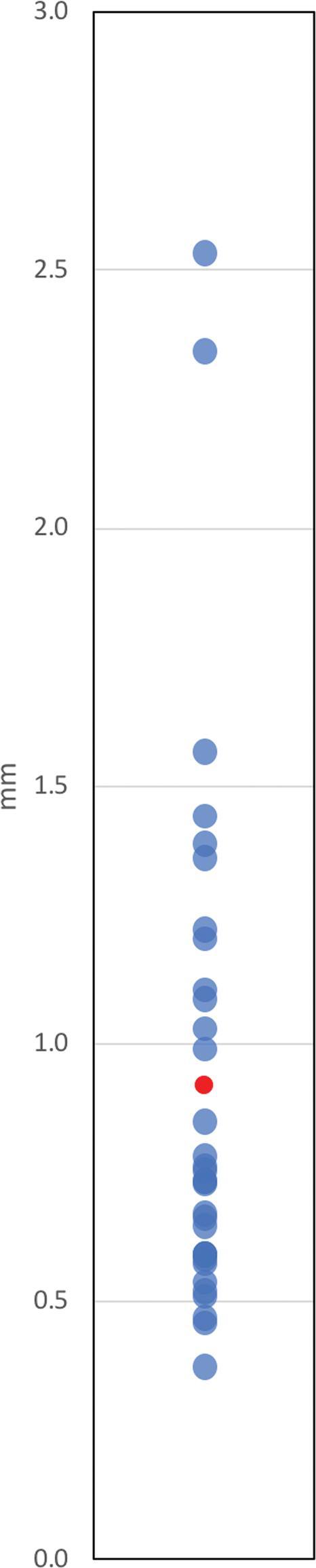
Euclidean differences (Y-axis) expressed in millimeters. Each value was observed once. Mean difference displayed in red.
FIGURE 6.

A-C, Marginal means of difference for vector differences, expressed in millimeters with 90% CI. A, X coordinates; B, Y coordinates; C, Z coordinates.
FIGURE 7.

A-C, Marginal means of difference for scalar differences, expressed in millimeters with 90% CI. A, X coordinates; B, Y coordinates; C, Z coordinates.
FIGURE 8.

Marginal means of difference for Euclidean difference, expressed in millimeters with 90% CI.
Maximum values represent the greatest magnitude of variation between the surgical plan coordinates produced from fused CT/MRI and O2/MRI and, by extension, the lowest observed degrees of accuracy and precision. The maximum vector difference observed between CT/MRI and O2/MRI coordinates was −2.500 mm, occurring in the Z direction. For the remaining coordinates, the maximum vector differences were 0.600 mm for X and 1.000 mm for Y. The maximum Euclidean difference calculated was 2.534 mm. These values are summarized in Table 2.
TABLE 2.
Summary of Differences Between Analogous Target Coordinates (O2-CT)
| Max | Mean | Std deviation | Std error | |
|---|---|---|---|---|
| (mm) | (mm) | (mm) | (mm) | |
| X (absa) | 0.600 | 0.236 | 0.166 | 0.029 |
| Y (absa) | 1.000 | 0.361 | 0.279 | 0.049 |
| Z (absa) | 2.500 | 0.727 | 0.535 | 0.093 |
| X (vecb) | 0.600 | 0.146 | 0.251 | 0.044 |
| Y (vecb) | 1.000 | 0.306 | 0.340 | 0.059 |
| Z (vecb) | −2.500 | −0.339 | 0.844 | 0.147 |
| Euclidean | 2.534 | 0.921 | 0.504 | 0.088 |
“abs”: absolute value (scalar) difference.
“vec”: vector difference.
The Bland–Altman plots in Figure 9 display the distribution of vector differences observed between CT/MRI and O2/MRI coordinates across X (Figure 9A), Y (Figure 9B), and Z (Figure 9C) orientations with additional visual reference points. Data points within the upper and lower limits of agreement show qualitatively good agreement with one another. Standard deviation is used in the Bland–Altman plots to follow convention.
FIGURE 9.

A-C, Bland–Altman Plots depicting distribution of differences across 3 coordinates. The X-axis illustrates the mean of the 2 values being compared. The center dashed line in each plot represents bias (mean difference). The dashed lines located above and below the bias line illustrate the upper and lower limits of agreement  . The solid-lines located above and below the upper and lower limits of agreement depict the 2-mm threshold of clinical relevance. A, X coordinates; B, Y coordinates; C, Z coordinates.
DISCUSSION
O-Arm as a Replacement for Frame Placement Registration CT
For planning of depth electrode placement for DBS or SEEG, we found the O2 to be accurate within an acceptable degree when compared to the traditional CT. Marginal means of difference were found within the predefined equivalence margins of −2 mm and 2 mm for vector, scalar, and Euclidean differences. These margins were defined arbitrarily as no specific threshold is widely accepted for assessing agreement between stereotactic planning modalities; however, a more stringent value may be appropriate as irregularities in frame registration and implantation will both contribute to deviation from intended targets. These results suggest fused O2/MRI scans may offer an acceptable level of accuracy and precision for electrode implantation planning.
The observed difference between CT/MRI and O2/MRI coordinates exceeded the predefined 2-mm threshold twice in the Z direction (−2.500 mm and −2.300 mm). Both outliers were observed in patient 2 (Table 1). At 0.339 ± 0.407 mm, the scalar marginal mean of difference for Z coordinates was greater than those for X (−0.146 ± 0.160 mm) and Y (−0.306 ± 0.106 mm) coordinates, as might be explained by a displacement from the CRW locking mechanism; the CRW frame clamping mechanism that secures the fiducial box is prone to error because of interference from the draping material. A clear drape, allowing for direct visualization of the locking mechanism, was used at the ring-arc interface to minimize these effects. However, the data suggest frame reattachment may have been suboptimal for patient 2 despite these precautions. A similar pattern was observed for vector marginal means of difference. The Bland–Altman plot depicting differences between Z coordinates illustrates that these findings were relative outliers (Figure 9C). Additionally, Table 1 reveals the Euclidean difference was greater than 2 mm twice and only in the same electrodes associated with the large Z differences.
Given the low levels of disagreement between the 2 imaging modalities, obtaining preimplantation O2 scans for surgical mapping may offer numerous advantages. Utilizing fused O2/MRI scans for electrode implantation planning would mitigate logistical burden by rendering intraoperative visits to the radiology department unnecessary for frame-registration CT imaging.9 Potential encumbrances presented by current standard planning CT protocol include challenges transporting the anesthetized patient and scheduling conflicts because of concurrent cases requiring CT scans. As a result, this modification may reduce overall operative time. The O-arm has also been shown to deliver up to 50% lower radiation doses than standard 64-slice CT scanners, thereby ensuring no increased radiation exposure with use of a planning O2 in lieu of a standard frame-registration CT scan.1,27
Just as the O-arm has been previously proposed as a feasible intraoperative alternative for postoperative CT scans, use of the O2 in a planning capacity may help further optimize delivery of care in stereotactic and functional neurosurgery. Although C-arm scans were obtained for select patients to guide the final approach of electrodes to intracranial targets, the O2 can be used to perform this function as well.1 By also generating target coordinates from fused O2/MRI scans, the O2 could serve as the sole imaging modality utilized from frame registration to confirmation of lead placement. Electrode locations shown on postimplantation merged O2/MRI scans could therefore be compared directly with merged planning O2/MRI scans. Utilizing the O2 in this manner would help to ensure any observed deviations from intended trajectories resulted from imperfect lead placement, rather than inherent differences between CT and O2 imaging.
Limitations of the O-Arm System
The O2 affords unique opportunities to optimize perioperative imaging in stereotactic neurosurgery, but the size of the device presents notable logistical challenges in the operating room. In certain orientations, the O2 may impede the ability of the anesthesiology team to manage the patient's airway or make other necessary corrections near the patient's face.1 Personnel must also develop sufficient familiarity with the unit to relocate it quickly and safely should an airway emergency or other unexpected event occur.
Proper use of the O2 requires not only an adequate staging area in the operating room but a clear path for navigation of the apparatus to and from the patient without risk of collision; accommodating the O2 may require significant reorganization of the suite. In 2D mode, the O-arm delivers radiation doses similar to the C-arm, requiring all personnel to utilize appropriate protective equipment.28,29 Mobile lead barriers and other essential equipment can further contribute to congestion in operating room. Although adopting O-arm scans in the proposed capacity may preclude separate CT imaging, it is critical to consider the potential impacts of increased radiation on the organization and workflow of the operating room. The O2 is also an expensive device, and the availability of the unit may be limited by use in other surgeries (particularly spine procedures).
From a technical perspective, the O-arm cannot provide well-defined soft tissue imaging and is therefore insufficient for standalone planning and confirmation of intracranial electrode placement.1,8 With the software and fusion algorithms currently available, preoperative MRIs must still be obtained for adequately detailed information concerning brain structure locations and are subsequently merged with O-arm scans. The limited ability of the O-arm to visualize soft tissues compared to CT also renders it much less capable of detecting intraoperative hematomas.1
Limitations of Study
Although the data collected showed low levels of disagreement, this study was limited by small sample size. Additionally, the Leksell Stereotactic System® was utilized for only 2 patients. Potential variation between O2 units was not evaluated in this study. Moreover, no investigation was made into potential changes in accuracy of the O2 over the lifetime of the device. This study was further limited by its small sample size of 7 patients (33 target coordinates). Given the potential impact of surgical draping errors in patient 2, it is possible data collected from a study including a greater number of patients would reflect greater consistency.
The acquisition of O2 scans during the confirmation stage following electrode implantation may constitute the most significant limitation of this study. Although lead positions were disregarded for analysis, collecting data from O2 scans at the preimplantation frame-registration stage would have strengthened the conclusion that this technology can be utilized accurately in a planning capacity; however, this method was not used in order to protect patients from additional radiation exposure. Intraoperative brain shift was also contemplated as a potential confounder, but previous studies have concluded these events likely have an insignificant impact on accurate identification of brain structure positions.1,30,31 By extension, the effects of nonsupine patient positioning during O2 imaging on our findings were therefore likely negligible. Furthermore, any disadvantages incurred by obtaining the O2 scans with inclined patient positioning and after electrode implantation are more likely to have exaggerated, rather than diminished, discrepancies between the 2 modalities. Similarly, the inclusion of 3 different surgical procedures in this study may have introduced unknown biases that amplify levels of disagreement between CT/MRI and O2/MRI target coordinates. Consequently, it is improbable that these limitations distorted the data in favor of our conclusions.
CONCLUSION
In the context of stereotactic and functional neurosurgery, fused O2/MRI scans may generate planning coordinates clinically consistent with those generated from fused CT/MRI scans. The low levels of disagreement observed between the 2 imaging techniques indicate the O2 may be used effectively for planning of electrode implantation, but further investigation is needed to minimize the discrepancies observed in this study. Similar to frame-registration CTs, however, O2 images must still be computationally merged with preoperative MRI studies to properly establish an internal frame of reference and construct appropriate surgical plans. The O2 may be appropriate for perioperative use as a core imaging modality, potentially eliminating the need for routine planning or postoperative CT scans.
Disclosures
This work was supported by the National Center for Advancing Translational Science (NCATS) of the United States National Institutes of Health (KL2TR001854) and the Neurosurgery Research and Education Foundation (NREF). The authors have no financial or personal interests to disclose regarding the devices, equipment, and software discussed in this study.
Acknowledgments
We thank Dr Philip Starr for a critical reading of the manuscript.
REFERENCES
- 1. Shahlaie K, Larson PS, Starr PA. Intraoperative computed tomography for deep brain stimulation surgery: technique and accuracy assessment. Oper Neurosurg. 2011;68(suppl_1):ons114-ons124. [DOI] [PubMed] [Google Scholar]
- 2. Yoshida F, Miyagi Y, Morioka T et al.. Assessment of contact location in subthalamic stimulation for Parkinson's disease by co-registration of computed tomography images. Stereotact Funct Neurosurg. 2008;86(3):162-166. [DOI] [PubMed] [Google Scholar]
- 3. Foltynie T, Zrinzo L, Martinez-Torres I et al.. MRI-guided STN DBS in Parkinson's disease without microelectrode recording: efficacy and safety. J Neurol Neurosurg Psychiatry. 2011;82(4):358-63. [DOI] [PubMed] [Google Scholar]
- 4. Burchiel KJ, McCartney S, Lee A, Raslan AM. Accuracy of deep brain stimulation electrode placement using intraoperative computed tomography without microelectrode recording. J Neurosurg. 2013;119(2):301-306. [DOI] [PubMed] [Google Scholar]
- 5. Richardson RM, Ostrem JL, Starr PA. Surgical repositioning of misplaced subthalamic electrodes in Parkinson's disease: location of effective and ineffective leads. Stereotact Funct Neurosurg. 2009;87(5):297-303. [DOI] [PubMed] [Google Scholar]
- 6. Anheim M, Batir A, Fraix V et al.. Improvement in Parkinson disease by subthalamic nucleus stimulation based on electrode placement: effects of reimplantation. Arch Neurol. 2008;65(5):612-616. [DOI] [PubMed] [Google Scholar]
- 7. Ellis T-M, Foote KD, Fernandez HH et al.. Reoperation for suboptimal outcomes after deep brain stimulation surgery. Neurosurgery. 2008;63(4):754-761. [DOI] [PubMed] [Google Scholar]
- 8. Carlson JD, McLeod KE, McLeod PS, Mark JB. Stereotactic accuracy and surgical utility of the O-Arm in deep brain stimulation surgery. Oper Neurosurg. 2016;13(1):96-107. [DOI] [PubMed] [Google Scholar]
- 9. Servello D, Zekaj E, Saleh C, Pacchetti C, Porta M. The pros and cons of intraoperative CT scan in evaluation of deep brain stimulation lead implantation: a retrospective study. Surg Neurol Int. 2016;7(Suppl 19):S551-556. [DOI] [PMC free article] [PubMed] [Google Scholar]
- 10. Starr PA, Martin AJ, Larson PS. Implantation of deep brain stimulator electrodes using interventional MRI. Neurosurg Clin. 2009;20(2):207-217. [DOI] [PubMed] [Google Scholar]
- 11. Larson PS, Starr PA, Bates G, Tansey L, Richardson RM, Martin AJ. An optimized system for interventional magnetic resonance imaging-guided stereotactic surgery: preliminary evaluation of targeting accuracy. Oper Neurosurg. 2011;70(suppl_1):ons95-ons103. [DOI] [PMC free article] [PubMed] [Google Scholar]
- 12. Mirzadeh Z, Chapple K, Lambert M, Dhall R, Ponce FA. Validation of CT-MRI fusion for intraoperative assessment of stereotactic accuracy in DBS surgery. Mov Disord. 2014;29(14):1788-1795. [DOI] [PubMed] [Google Scholar]
- 13. Pinsker M, Herzog J, Falk D, Volkmann J, Deuschl G, Mehdorn M. Accuracy and distortion of deep brain stimulation electrodes on postoperative MRI and CT. Zentralbl Neurochir. 2008;69(03):144-147. [DOI] [PubMed] [Google Scholar]
- 14. Nottmeier EW, Seemer W, Young PM. Placement of thoracolumbar pedicle screws using three-dimensional image guidance: experience in a large patient cohort. J Neurosurg Spine. 2009;10(1):33-39. [DOI] [PubMed] [Google Scholar]
- 15. Brennan RP, Smucker PY, Horn EM. Minimally invasive image-guided direct repair of bilateral L-5 pars interarticularis defects. J Neurosurg. 2008;25(2):E13. [DOI] [PubMed] [Google Scholar]
- 16. Caire F, Gantois C, Torny F, Ranoux D, Maubon A, Moreau J-J. Intraoperative use of the Medtronic O-arm for deep brain stimulation procedures. Stereotact Funct Neurosurg. 2010;88(2):109-114. [DOI] [PubMed] [Google Scholar]
- 17. Kitai R, Sato K, Ido K, Sakuma T, Handa Y, Kubota T. Single burr hole surgery for the spheno-orbital fibrous dysplasia using intraoperative computed tomography. Minimal Invas Neurosurg. 2005;48(01):44-46. [DOI] [PubMed] [Google Scholar]
- 18. Engle DJ, Lunsford LD.. Brain tumor resection guided by intraoperative computed tomography. J Neurooncol. 1987;4(4):361-370. [DOI] [PubMed] [Google Scholar]
- 19. Frizon LA, Shao J, Maldonado-Naranjo AL et al.. The safety and efficacy of using the O-Arm intraoperative imaging system for deep brain stimulation lead implantation. Neuromodulation. 2018;21(6):588-592. [DOI] [PubMed] [Google Scholar]
- 20. Sabour S. A quantitative assessment of the accuracy and reliability of O-arm images for deep brain stimulation surgery. Neurosurgery. 2013;72(4):E696-E696. [DOI] [PubMed] [Google Scholar]
- 21. Nakajima T, Zrinzo L, Foltynie T et al.. MRI-guided subthalamic nucleus deep brain stimulation without microelectrode recording: can we dispense with surgery under local anaesthesia? Stereotact Funct Neurosurg. 2011;89(5):318-325. [DOI] [PubMed] [Google Scholar]
- 22. Aviles-Olmos I, Kefalopoulou Z, Tripoliti E et al.. Long-term outcome of subthalamic nucleus deep brain stimulation for Parkinson's disease using an MRI-guided and MRI-verified approach. J Neurol Neurosurg Psychiatry. 2014;85(12):1419-25. [DOI] [PMC free article] [PubMed] [Google Scholar]
- 23. Chen T, Mirzadeh Z, Ponce FA. “Asleep” deep brain stimulation surgery: a critical review of the literature. World neurosurg. 2017;105:191-198. [DOI] [PubMed] [Google Scholar]
- 24. Rothschild PA, Domesek JM, Eastham ME, Kaufman L. MR imaging of excessively obese patients: the use of an open permanent magnet. Magn Reson Imaging. 1991;9(2):151-154. [DOI] [PubMed] [Google Scholar]
- 25. Berg WA, Blume JD, Adams AM et al.. Reasons women at elevated risk of breast cancer refuse breast MR imaging screening: ACRIN 6666. Radiology. 2009;254(1):79-87. [DOI] [PMC free article] [PubMed] [Google Scholar]
- 26. Sharma M, Deogaonkar M.. Accuracy and safety of targeting using intraoperative “O-arm” during placement of deep brain stimulation electrodes without electrophysiological recordings. J Clin Neurosci. 2016;27:80-86. [DOI] [PubMed] [Google Scholar]
- 27. Zhang K, Bhatia S, Oh MY, Cohen D, Angle C, Whiting D. Long-term results of thalamic deep brain stimulation for essential tremor. J Neurosurg. 2010;112(6):1271-1276. [DOI] [PubMed] [Google Scholar]
- 28. Smith-Bindman R, Lipson J, Marcus R et al.. Radiation dose associated with common computed tomography examinations and the associated lifetime attributable risk of cancer. Arch Intern Med. 2009;169(22):2078-2086. [DOI] [PMC free article] [PubMed] [Google Scholar]
- 29. de González AB, Mahesh M, Kim K-P et al.. Projected cancer risks from computed tomographic scans performed in the United States in 2007. Arch Intern Med. 2009;169(22):2071-2077. [DOI] [PMC free article] [PubMed] [Google Scholar]
- 30. Miyagi Y, Shima F, Sasaki T. Brain shift: an error factor during implantation of deep brain stimulation electrodes. J Neurosurg. 2007;107(5):989-997. [DOI] [PubMed] [Google Scholar]
- 31. Halpern CH, Danish SF, Baltuch GH, Jaggi JL. Brain shift during deep brain stimulation surgery for Parkinson's disease. Stereotact Funct Neurosurg. 2008;86(1):37-43. [DOI] [PubMed] [Google Scholar]