Abstract
Objectives:
An impactor is a standard instrument that applied for particle deposition assessment in the pharmaceutical aerosols. It provides data comparison between inhaler formulations. However, the deposition pattern in the impactor is not clearly understood. In practice monodisperse aerosols were employed to calibrate the impactor.
Materials and Methods:
This study used polydisperse aerosols together with the computer simulation to track the particles in the impactor to understand the deposition pattern. Particles deposited on each stage of the Andersen cascade impactor were compared with its stage cut-off diameter using polydisperse aerosols by three particle sizing techniques. The relationship of cut-off diameter with particle size distribution was established for each stage. Also, the computational verification was used to complement the real experiments.
Results:
Projected diameters from microscope images showed that the size of particles varied on the stage’s collection plate, and the median size of each stage decreased along the lower stages from 8.53 to 0.92 μm. The median sizes measured by laser diffraction were close to the impactor’s cut-off diameters. In silico data showed that the outlet mass fractions gradually changed in size towards the lower stages.
Conclusion:
Polydisperse aerosols and in silico computer fluid dynamics may compliment to standard calibration method.
Keywords: Particle size distribution, computer fluid dynamic, andersen cascade impactor, polydisperse aerosols
INTRODUCTION
The particle deposition pattern and air flow in the pulmonary system are of great importance for pulmonary drug delivery. An impactor is a standard instrument applied for particle deposition assessment of pharmaceutical aerosols. Even if the impactor does not perfectly represent a realistic respiratory tract, it provides data for comparing formulations and products.1 The Andersen cascade impactor (ACI) is a conventional cascade impactor that has been used in various aerosol studies.2,3,4 The ACI has been developed to characterize aerodynamic particle size distribution (PSD) and particle deposition, by using an inertial impactor so that the aerodynamic size affects the inertial forces, and different sizes are collected on individual collection plates.5 The standard ACI has eight stages. Each stage has been designed to collect particles in a range of inertial forces that are affected by nozzle size and flow patterns. The impactor stage specifically traps aerosol particles according to a cut-off diameter, and the collected mass represents the aerosol amount in the size range of that stage.
Other particle assessment techniques include laser diffraction, time of flight, and microscopy, giving PSD. De Boer et al.6 successfully developed a laser diffraction technique to measure micronized powder aerosols. Laser diffraction has been used to determine the size of deposited particles either prior to or subsequent to entering through the impactor.7,8 Haynes et al.9 showed a good correlation between the volume median diameter and the mass median aerodynamic diameter (MMAD) obtained by Spraytec® and the ACI, respectively, with R2=0.8037. The particle deposition is reproducible and there is a strict correlation with the impactor in the case of liquid formulations.8 Microscopy can allow direct particle size measurement and observation of particle morphology. This technique provides both qualitative and quantitative data for characterizing aerosols from dry powder inhalers. The projected area diameter is used to describe the particle size in its most stable plane.10
Monodisperse aerosols are defined as those with narrow PSD, and they are widely used in many applications, including aerosol sizing apparatus calibration, medical delivery systems, and experimental testing of models.7,11,12,13,14 Monodisperse aerosols are applied in the calibration of aerosol sizing apparatuses, and for example fluorescent dye monodisperse aerosols are generated in specific calibration particle sizes by a vibrating orifice aerosol generator and are immediately fed to the impactor.7,12 Polydisperse aerosols are more common in pharmaceutical formulations as defined by a broader PSD, specifically having a geometric standard deviation (GSD) higher than 1.25.15,16 Polydisperse aerosols are rarely used as calibrants, although there are some studies using polydisperse aerosols to compare two impactors.16,17 However, the well-known calibration procedures use monodisperse aerosols. Srichana et al.13 published a calibration method using spherical silica for the ACI; the monodisperse particle sizes were separately introduced to determine the collection efficiency curve of the preseparator and stages 0 to stage 4. In addition, dry powder polydisperse aerosols from blends of monodisperse silica powders have been employed for calibration.13 Computational fluid dynamics (CFD) has been employed in the simulation of fluid flow and in particle tracking in the impactor. In our previous study, a preseparator-equipped ACI showed airflow smoothing to the next stage.18 Moreover, the single jet model and the quarter ACI model have been validated in the sense that the particle collection efficiency showed excellent correlation with experiments.14,19 However, prior information on polydisperse particle deposition in the ACI is lacking. The aim of the current research was to study the particle paths and deposition using polydisperse aerosols in an ACI and assess the behavior of polydisperse aerosols regarding deposition in the impactor. The particles on the collection plates were collected and analyzed by particle sizing techniques, namely by laser diffraction and microscopy. The research was conducted by observation of the PSD using actual experiments and by particle tracking simulations of each stage using CFD.
MATERIALS AND METHODS
Particle production
Polydisperse mannitol particles were obtained by spray drying mannitol solution using a mini spray dryer (Buchi B-290, Switzerland) with a high-performance cyclone and nano spray dryer (Buchi B-90, Switzerland) under different conditions until 5 size ranges of particles were obtained (1-10 µm). Three size ranges of silica microspheres were prepared by dispersing in 3 mL of methanol and adjusting the volume with HFA-134a to make a 10 mL pressurized silica suspension (0.2-1.2 µm). These mannitol and silica particles were first characterized by scanning electron microscopy (SEM) before being subjected to the ACI for particle deposition.
ACI operation
The eight stages of the ACI include the preseparator and stage -1 to stage 6, and the filter and base stage were operated to monitor particle deposition. First, 20 mg of spray-dried mannitol was placed in the in-house dry powder inhaler device20 or the pressurized silica suspension, and the sources were coupled with the ACI by a metal inlet. Then the ACI was first tested at 60 L/minfor 10 s to ensure all aerosol particles were delivered completely into the ACI. The trapped particles on each stage were analyzed for their deposition pattern by laser diffraction and microscopy. For spray-dried mannitol, the collection plates were separately rinsed with de-ionized water and the dissolved mannitol contents for each stage were analyzed using HPLC.21 Samples (100 µL) were injected into a resolved C-18 column (5 µm, 150 mm×3.9 mm, Waters, Milford, MA, USA) using de-ionized water as a mobile phase, at a flow rate of 1 mL/min. The retention time was about 4 min. A refractive index detector (Model RID-10A; Shimadzu, Kyoto, Japan) was used. A calibration curve was constructed using standard solutions of mannitol from 10 to 400 µg/mL. The MMAD and GSD were calculated simultaneously.
Laser diffraction
Pre-ACI: A Spraytec® (Malvern, Worcestershire, UK) equipped with a USP inlet was used in place of the inhalation cell. The equipment was connected directly to a particle-collecting filter and vacuum pump. The PSDs of spray-dried mannitol particles were characterized by suspending in air using the laser diffraction technique via the Spraytec®. The flow rate was set at 60 L/min in the measurement zone and 2% obscuration was set as a trigger for all measurements. Post-ACI: The collected mannitol particles were gently removed from the collection plates. The Spraytec® was then used to characterize the particle size deposition on each stage. Second, the silica particles on the last three stages (S4-S6) were rinsed individually using methanol and particle samples were allowed to equilibrate at 25°C for 2 min. Then size distribution was determined by the Zetasizer Nano ZS (Malvern, UK). Dynamic light scattering measurements were carried out at 173° scattering angle (backscatter detection) using the Malvern Zetasizer Nano ZS. Three measurements were made for 10 runs for each sample. The viscosity and refractive index of the dispersant were set at 0.5476 cP and 1.326, respectively. For the silica particles, the refractive index (1.458) and absorption (0.001) were used to calculate the size distributions by volume and by particle count. The Z-average, polydisperse index, and median values were used for comparison of the different techniques.
Microscopic analysis
Double adhesive discs (3M, Bangkok, Thailand) were prepared and placed on each collection plate to trap the particles that lost their momentum. Five hundred particles were examined by light microscopy using particle sizing analysis software (cell^P, Olympus Soft Imaging Solutions GmbH, Münster, Germany). After the number count based size distribution had been determined by microscopy this PSD was compared with those from other techniques. The Hatch–Choate transformation equation was used to convert the by number distribution to the by weight distribution. The logarithm of the particle size (x-axis) was plotted against the cumulative percent frequency on a probability scale (y-axis).
Experimentally, spray-dried mannitol was continuously introduced into the ACI, where the Spraytec® was operated at 60 L/min with the assistance of a dry powder device to deagglomerate the dry powder into single particles.22,23 Then the projected diameters of trapped particles were analyzed by microscopy.
Computational simulation
Figure 1 shows the ACI model developed from previous work including face sizing for continuation of the face to completely transfer to the mathematical model.18 One-third of the model was used instead of the whole cascade impactor to simplify the complex calculation. The Navier–stokes equations were solved by the finite volume method. The turbulence model used was realizable k-ε and standard wall functions were selected to solve the fluid flow equations as a good fit was given with the empirical data.
Figure 1.
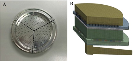
Divided Andersen cascade impactor stage dimensions A) and the computation model of impactor B)
Particle motion equation: model description
he particle tracking employed the discrete phase simulation in Fluent by Lagrangian discrete phase model based on one-way coupling. The discrete phase simulation was based on the assumption that the discrete phase occupies a low volume fraction (Vp<<Vair) with a high loading mass (mp≤mair). The original particle condition is gravitation and the initial velocity was specified as a constant with a fully turbulent profile, and no-slip conditions were applied at the walls.24 The spherical particle model was employed for particles larger than 1 µm, whereas those in the size range 0.1-0.9 µm were treated with the Stokes–cunningham model, which provides a slip correction factor. The stochastic tracking approach was used to predict the turbulent dispersion of the particles to mimic the real situation as the particles were traveling in the air (Equation 1).
Impaction parameter and particle kinetic energy
Kinetic energy (Ke) is employed in trapping particles on the collection plate. The regular trap boundary condition leads to underestimation of the collection plate cut-off diameter.25 Therefore, a user defined function (UDF) was developed following the kinetic Equations 2-4. The density of silica particles was 1.8 g/mL and mannitol had density 1.5 g/mL.
Particle deposition simulation
The deposition factor was the total deposition within the stage of interest and could be explained by the Lagrangian model simulations as the number of discrete particles that were deposited on the collection plate. The deposition efficiency (DE) was defined by Equation 5.
Particle size distribution model for tracking a group of particles
The chosen PSD was Rosin–Rammler. The Rosin–Rammler distribution function gives an exponential relationship between the particle diameter (d) and the mean particle diameter26 as shown in Equation 6.
In this case, the spread parameter was 2.071 and the maximum diameter was 8.71 µm, while the minimum diameter was 0.21 µm and the number-average mean diameter of the Rosin–rammler distribution was 3.36 µm with 28 segments of particle size. The trajectory of the sample histograms was used to describe the PSDs on each collection plate and at the outlet of each stage. The diameter of the particles was set as a variable. In the present study, the particle deposition efficiency of each stage was calculated by the number of particles trapped on the collection plate divided by the number of particles entering each stage. The simulated PSD from the outlet of the upper stage was used as an inlet PSD of particles of the following stage. The PSD was introduced into a computer simulation and the particle distributions on each stage of the ACI were computationally modeled.
The submitted protocol entitled “Deposition pattern of polydisperse dry powders in Andersen cascade impactor” including all related documents has been reviewed by the Health Science Human Research Ethics Committee, Prince of Songkla University (ref:161/2760).
RESULTS AND DISCUSSION
Particle morphology and surface characteristics
Figures 2 and 3 show the morphology and surface of spray-dried mannitol and silica microspheres, viewed under SEM. The mannitol prepared using a spray dryer and nano spray dryer presented perfectly spherical shapes with smooth surfaces. All silica microspheres were perfectly spherical with smooth surfaces.
Figure 2.
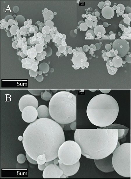
Morphology and surface characteristics of spray-dried mannitol by scanning electron microscopy imaging: mannitol spray-dried using a mini spray dryer A) and mannitol spraydried using a nano spray dryer B)
Figure 3.
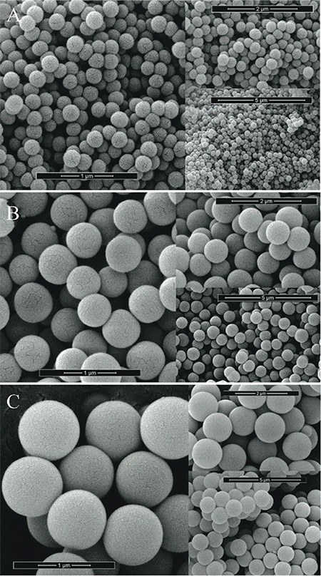
Morphology and surface characteristics of monodisperse silica microspheres:monodisperse silica microspheres of sizes 0.261, 0.690, and 1.18 μm, respectively
Particle size distribution of spray-dried mannitol and silica microspheres
The median size (Dv0.5 ± SD) was 3.53±0.09 µm with size at 90% cumulative (Dv0.9) of 8.62±0.66 µm and size at 10% cumulative (Dv0.1) of 0.92±0.47 µm. The spray-dried mannitol had polydisperse PSD with a span of 2.18. The span is the measurement of the width of the size distribution. The smaller the value the narrower the distribution. The width is calculated by (Dv0.9-Dv0.1)/Dv0.5. The PSDs revealed a spread of particle sizes in spray-dried mannitol. The specific sizes of silica were 0.261, 0.690, and 1.18 µm with narrow distribution.
Depositions of mannitol and silica particles on each ACI stage
The mean diameters of mannitol and silica particles from microscopy are shown in Table 1. Microscopy also confirmed the spherical shape of particles captured on the adhesive film (Figure 4). Large particles were mostly isolated and had been collected on an early stage of the impactor, while agglomeration of some primary particles may have occurred during ACI processing. The spray-dried mannitol particles exhibited some agglomeration of small particles. The agglomerates behaved like larger particles and were trapped by the early stages of the ACI. However, individual particles did not change their sizes when viewed under the microscope. From the microscopy results, the particle size of deposited particles decreased along the stages, for example the particle mean diameter of deposited particles on stage 6 was 0.92 µm, which was close to the limits of optical microscopy. Particle deposition depends on the stage cut-off diameter and on the inertial forces of the particles, which relate directly to particle morphology and size. Most of the particle population stayed under the stage nozzle of similar sizes, where the smaller particles escaped to the next stage via the air stream because of their lower inertial forces.18 Each collection plate trapped the particles with sufficient inertial force.
Table 1. The geometric mean diameter (μm) on weight basis, obtained using the Hatch-Choate equation with microscopy data.
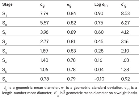
Figure 4.
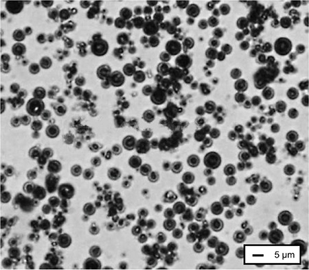
Deposition pattern of spray-dried mannitol on stage 0 collection plate observed with optical microscope: 50× magnification
The spray-dried mannitol had median diameters of 3.02, 3.91, 7.02, and 9.59 µm. Therefore, the particle size range covered the cut-off diameters of stage -1 to stage 3 at a flow rate of 60 L/min. The spray-dried mannitol was introduced into the ACI. The comparison between the manufacture’s nominal cut-off and the actual deposition of particles (spray-dried mannitol) is shown in Figure 5. The median particle size deposition on each stage’s collection plate matched reasonably well with the nominal cut-off diameters. The cut-off diameters usually were obtained by the amount of specific trapped particle size on the stage of interest compared with the whole impactor using individual monodisperse particle size. The results for spray-dried mannitol showed a good match of the median size of deposited spray-dried mannitol and the manufacturer’s nominal data on impactor stages. However, it was not possible to evaluate with this spray-dried mannitol the particle deposition in the lower stages (stage 4 or lower) because the cut-off diameters are too small relative to the prepared particle sizes.
Figure 5.
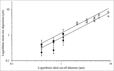
The correlation between logarithmic ideal size cut-off and logarithmic mean size deposition of spray dried mannitol: 3.02 μm (◊), 3.91 μm (□), 7.02 μm (△), 9.59 μm (○), and microsphere silica: 0.26 μm (■), 0.69 μm (▲), and 1.18 μm (●) on each stage
Silica microsphere deposition on each ACI stage
The mean particle size trapped by each collection plate is shown in Figure 5. For stages 4 to 6, the spherical silica particles were in the appropriate size range. Three size ranges of silica particles (0.261, 0.690, and 1.180 µm) were introduced into the ACI (n=5). Three cases of silica microspheres clearly escaped through the nozzle of stage 4, with mean size of trapped silica particles close to the manufacturer’s cut-off data with relative accuracies from 71.4% to 127.6%. The higher error of the correlation could be explained by particle aggregation. The mean particle size of trapped particles on stage 5’s collection plate showed good agreement with the stage cut-off using silica microspheres within 94.4% and 106.3% relative accuracy. For the trapped particles on stage 6’s collection plate, the data showed good correlation between the microsphere deposition and the stage’s cut-off diameter with 90.85%-106.90% correlation. In brief, the particle depositions on the collection plate show the aggregated particles could form a larger diameter clump and be prematurely trapped on the earlier stage of the impactor. Moreover, the laser diffraction results showed good correlation of deposition on each collection plate with the respective nominal cut-off diameters.13,27,28 The mean size of trapped particles on each stage could be representative of the stage cut-off diameter, while the PSD allowed estimation of collection efficiency curves.
Computational particle tracking and deposition
The particles were tracked along the computational ACI model (60 L/min) to study particle paths in the impactor. The validation of the computational model had been confirmed using the collection efficiency curves of the computational simulation obtained by injecting individual particles from 0.3 µm to 11 µm in size. The simulated capture rate curves at 50% collection efficiency gave cut-off diameter estimates matching the manufacturer’s nominal values well. The experimental particle deposition results were comparable to the simulation results for the ACI. The particle deposition in the ACI was expressed as percent by mass across the distribution of particle sizes in the aerosol. The amounts of spray-dried mannitol on each collection plate were analyzed by LC with an RI detector as shown in Figure 6. The MMAD of spray-dried mannitol was 4.08 µm with a GSD of 1.75 for 60 L/min. Figure 7 shows the simulated PSDs at outlets of each stage, by mass fractions of spray-dried mannitol following injection with Rosin–Rammler PSD. These simulations at the outlet of stage -1 showed that 50% of particles were around 4 µm. The MMAD of the simulated particles at the outlet exhibited decreasing size when they passed through the impactor stage with the smaller cut-off diameter. The simulated PSD had an MMAD at 4.08 µm, whereas the experimental particle size was 4.15 µm. PSD was not significantly distorted until stage 3, which has a cut-off diameter below the MMAD. For example, the diameter was close to 1.20 µm at the outlet of stage 3, while the cut-off diameter of stage 4 is 1.10 µm. The simulations provided an explanation of how spray-dried mannitol was deposited and traveled across the ACI. Even if the aerosol particles were polydisperse, they were trapped by specific collection plates. In the present study, the particle deposition simulation gave for each particle size a capture probability and it confirmed that monodisperse aerosols are ideal for calibrating the ACI.13,28,29 However, the simulation of polydisperse spray-dried mannitol explained the particle flow behavior by mass fraction captured of each particle size. In the case of polydisperse aerosols, the impactor should separate the polydisperse samples as they were fed into the impactor.
Figure 6.
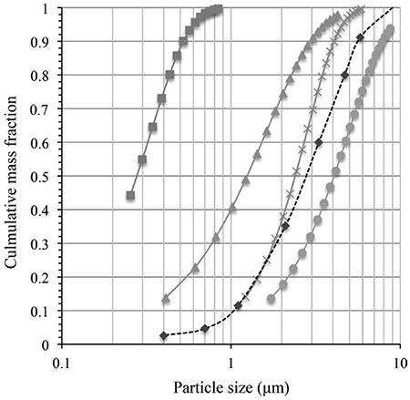
PSD by mass across particle sizes at the outlet of each individual stage as simulated outlet: Stage 1 (□), Stage 1 (□), Stage 3 (□), Stage 4 (□) and experimental data (□), spraydried mannitol
PSD: Particle size distribution
Figure 7.
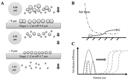
Illustrations of polydisperse particles passing by impactors A) and B), and particle distribution on each stage of a polydisperse mixture in impactor C)
CONCLUSION
Polydisperse aerosols were characterized and used to test an ACI successfully. This study assessed particle deposition in a cascade impactor using both experiments and computational simulations of dry particulate powder. Polydisperse dry powders behaved in accordance with the computational simulation based on inertial and aerodynamic drag forces one particle at a time. The tested particle sizing techniques, based on laser diffraction and optical microscopy, showed results comparable with the impactor manufacturer’s nominal cut-off data with polydisperse dry powders. The use of polydisperse dry powders in determining separation characteristics of the ACI was demonstrated using particle travelling path.
Acknowledgments
We would like to thank the Drug Delivery System Excellence Center for the use of their facilities. This work was supported by the Higher Education Research Promotion and National Research University Project of Thailand, Office of the Higher Education Commission. We would also like to thank the reviewers of this article and Dr. Seppo Karrila for assistance with manuscript preparation.
Footnotes
Conflicts of interest: No conflict of interest was declared by the authors. The authors alone are responsible for the content and writing of this article.
References
- 1.Mitchell J, Newman S, Chan HK. In vitro and in vivo aspects of cascade impactor tests and inhaler performance: A review. AAPS PharmSciTech. 2007;21:110. doi: 10.1208/pt0804110. [DOI] [PMC free article] [PubMed] [Google Scholar]
- 2.Duan Q, An JL, Wang HL, Miao Q. Pollution characteristics of organic and elemental carbon in atmospheric particles in Nanjing northern suburb in summer. Huan J ing Ke Xue. 2014;35:2460–2467. [PubMed] [Google Scholar]
- 3.Li Y, Zhang H, Qiu X, Zhang Y, Wang H. Dispersion and risk assessment of bacterial aerosols emitted from rotating-brush aerator during summer in a wastewater treatment plant of xi’an, china. Aerosol Air Qual Res. 2013;13:1807–1814. [Google Scholar]
- 4.Srichana T, Juthong S, Thawithong E, Supaiboonpipat S, Soorapan S. Clinical equivalence of budesonide dry powder inhaler and pressurized metered dose inhaler. Clin Respir J. 2016;10:74–82. doi: 10.1111/crj.12188. [DOI] [PubMed] [Google Scholar]
- 5.Marple VA, Liu BYH. Characteristics of laminar jet impactors. Environ Sci Technol. 1974;8:648–654. [Google Scholar]
- 6.De Boer AH, Gjaltema D, Hagedoorn P, Frijlink HW. Characterization of inhalation aerosols: A critical evaluation of cascade impactor analysis and laser diffraction technique. Int J Pharm. 2002;249:219–231. doi: 10.1016/s0378-5173(02)00526-4. [DOI] [PubMed] [Google Scholar]
- 7.Kwon SB, Lim KS, Jung JS, Bae GN, Lee KW. Design and calibration of a 5-stage cascade impactor (K-JIST cascade impactor) J Aerosol Sci. 2003;34:289–300. [Google Scholar]
- 8.Wachtel H, Ziegler J. Laser diffraction method for particle size distribution measurements in pharmaceutical aerosols. US. 2005. doi: 10.1089/jam.2005.18.311. [DOI] [PubMed] [Google Scholar]
- 9.Haynes A, Shaik MS, Krarup H, Singh M. Evaluation of the Malvern Spraytec® with inhalation cell for the measurement of particle size distribution from metered dose inhalers. J Pharm Sci. 2004;93:349–363. doi: 10.1002/jps.10558. [DOI] [PubMed] [Google Scholar]
- 10.Concessio NM, Hickey AJ. Descriptors of irregular particle morphology and powder properties. Adv Drug Deliv Rev. 1997;26:29–40. doi: 10.1016/s0169-409x(97)00508-5. [DOI] [PubMed] [Google Scholar]
- 11.Biddiscombe MF, Usmani OS, Barnes PJ. A system for the production and delivery of monodisperse salbutamol aerosols to the lungs. Int J Pharm. 2003;254:243–253. doi: 10.1016/s0378-5173(03)00032-2. [DOI] [PubMed] [Google Scholar]
- 12.Rader DJ, Mondy LA, Brockmann JE, Lucero DA, Rubow KL. Stage response calibration of the Mark III and Marple personal cascade impactors. Aerosol Sci Technol. 1991;14:365–379. [Google Scholar]
- 13.Srichana T, Martin GP, Marriott C. Calibration method for the Andersen cascade impactor. J Aerosol Sci. 1998;29:761–762. [Google Scholar]
- 14.Vinchurkar S, Longest PW, Peart J. CFD simulations of the Andersen cascade impactor: Model development and effects of aerosol charge. J Aerosol Sci. 2009;40:807–822. [Google Scholar]
- 15.Arefin AME, Masud MH, Joardder MUH, Akhter S. A monodisperse-aerosol generation system: Design, fabrication and performance. Particuology. 2017;34:118–125. [Google Scholar]
- 16.Rosati JA, Brown JS, Peters TM, Leith D, Kim CS. A polydisperse aerosol inhalation system designed for human studies. J Aerosol Sci. 2002;33:1433–1446. [Google Scholar]
- 17.Yoshida H, Kuwana A, Shibata H, Izutsu KI, Goda Y. Comparison of aerodynamic particle size distribution between a next generation impactor and a cascade impactor at a range of flow rates. AAPS PharmSciTech. 2017;18:646–653. doi: 10.1208/s12249-016-0544-9. [DOI] [PubMed] [Google Scholar]
- 18.Dechraksa J, Suwandecha T, Maliwan K, Srichana T. The comparison of fluid dynamics parameters in an Andersen cascade impactor equipped with and without a preseparator. AAPS PharmSciTech. 2014;15:792–801. doi: 10.1208/s12249-014-0102-2. [DOI] [PMC free article] [PubMed] [Google Scholar]
- 19.Gulak Y, Jayjock E, Muzzio F, Bauer A, McGlynn P. Numerical calibration of the Andersen cascade impactor using a single jet model. Int J Pharm. 2009;377:45–51. doi: 10.1016/j.ijpharm.2009.04.051. [DOI] [PubMed] [Google Scholar]
- 20.Sukasame N, Nimnoo N, Suwandecha T, Srichana T. Pharmacodynamics of dry powder formulations of salbutamol for delivery by inhalation. Asian Biomedicine. 2011;5:475–483. [Google Scholar]
- 21.Adi H, Young PM, Chan HK, Agus H, Traini D. Co-spray-dried mannitolciprofloxacin dry powder inhaler formulation for cystic fibrosis and chronic obstructive pulmonary disease. Eur J Pharm Sci. 2010;40:239–247. doi: 10.1016/j.ejps.2010.03.020. [DOI] [PubMed] [Google Scholar]
- 22.Ding Y, Riediker M. A system to assess the stability of airborne nanoparticle agglomerates under aerodynamic shear. J Aerosol Sci. 2015;88:98–108. [Google Scholar]
- 23.Miansari M, Qi A, Yeo LY, Friend JR. Vibration-induced deagglomeration and shear-induced alignment of carbon nanotubes in air. Adv Funct Mater. 2015;25:1014–1023. [Google Scholar]
- 24.Worth Longest P, Vinchurkar S. Validating CFD predictions of respiratory aerosol deposition: Effects of upstream transition and turbulence. J Biomech. 2007;40:305–316. doi: 10.1016/j.jbiomech.2006.01.006. [DOI] [PubMed] [Google Scholar]
- 25.Matida EA, Finlay WH, Lange CF, Grgic B. Improved numerical simulation of aerosol deposition in an idealized mouth-throat. J Aerosol Sci. 2004;35:1–19. [Google Scholar]
- 26.Bailey AG, Balachandran W, Williams TJ. The rosin--rammler size distribution for liquid droplet ensembles. J Aerosol Sci. 1983;14:39–46. [Google Scholar]
- 27.Garmise RJ, Hickey AJ. Calibration of the Andersen cascade impactor for the characterization of nasal products. J Pharm Sci. 2008;97:3462–3466. doi: 10.1002/jps.21267. [DOI] [PubMed] [Google Scholar]
- 28.Nichols SC, Brown DR, Smurthwaite M. New concept for the variable flow rate Andersen cascade impactor and calibration data. J Aerosol Med. 1998;11:133–138. [PubMed] [Google Scholar]
- 29.Dodge LG. Calibration of the Malvern particle sizer. Appl Opt. 1984;23:2415–2419. doi: 10.1364/ao.23.002415. [DOI] [PubMed] [Google Scholar]


