

Abstract
Dental implants are widely accepted for the rehabilitation of missing teeth due to their aesthetic compliance, functional ability, and great survival rate. The various components in implant design like thread design, thread angle, pitch, and material used for manufacturing play a critical role in its success. Understanding these influencing factors and implementing them properly in implant design can reduce cases of potential implant failure. Recently, finite element analysis (FEA) is being widely used in the field of health sciences to solve problems in designing medical devices. It provides valid and accurate assessment in the clinical and in vitro analysis. Hence, this study was conducted to evaluate the impact of thread design of the implant and 3 different bioactive materials, titanium alloy, graphene, and reduced graphene oxide (rGO) on stress, strain, and deformation in the implant system using FEA. In this study, the FEA model of the bones and the tissues are modeled as homogeneous, isotropic, and linearly elastic material with a titanium implant system with an assumption of it 100% osseointegrated into the bone. The titanium was functionalized with graphene and graphene oxide. A modeling software tool Catia® and Ansys Workbench® is used to perform the analysis and evaluate the von Mises stress distribution, strain, and deformation at the implant and implant-cortical bone interface. The results showed that the titanium implant with a surface coating of graphene oxide exhibited better mechanical behavior than graphene, with mean von Mises stress of 39.64 MPa in pitch 1, 23.65 MPa in pitch 2, and 37.23 MPa in pitch 3. It also revealed that functionalizing the titanium implant will help in reducing the stress at the implant system. Overall, the study emphasizes the use of FEA analysis methods in solving various biomechanical issues about medical and dental devices, which can further open up for invivo study and their practical uses.
1. Introduction
Dental implants are widely accepted by patients for the rehabilitation of partially edentulous arches due to its aesthetic compliance, functional ability, and great survival rate [1]. The appropriate selection of implant design is critical, as it plays an important role to preserve the osseointegration [2]. The success of the dental implant and osseointegration of bone-implant are influenced by several elements including material biocompatibility, implant design, surface treatment, surgical technique, bone quality, and loading conditions [3, 4]. In an attempt to study the biomechanical factors, researchers have targeted the implant macrodesign that affects the long-term success of the implant.
The thread in the implant acts as a retentive element, increasing the contact surface area to provide greater bone-implant interaction, thus providing better stress distribution [5–8]. The thread design, the pitch of the implant, and the material of implant help to determine the longevity and primary stability of the implant under immediate loading conditions [9, 10]. The high mechanical strength, corrosion resistance, fracture toughness, and excellent biocompatibility property make titanium alloys the most preferred and established biomedical material for implant fabrication [11, 12]. However, it is observed that the formation of an oxidized layer on its surface obstructs the interface of the implant and contacting bone tissues leading to inadequate integration with the adjoining bone. The formation of this biofilm also leads to increased susceptibility to infection, therefore leading to implant failure [13].
Several kinds of research have explored implants coated with hydroxyapatite (HA) and have recommended that, for anterior and posterior maxilla, HA-coated screw implants should be used where the depth of the bone reaches 10 mm and where the cortical layer is thinner. When the cortical layer of the posterior maxilla is thin and of low density, it is recommended to have an HA-coated cylindrical implant. However, the use of HA-coated implants is a concern, as the clinician should consider bacterial susceptibility of HA-coated implants in comparison with titanium implants. Besides, failure may also be observed due to coating-substrate fracture [14, 15].
Further studies led to exploring newer composite materials in dental applications termed as bioactive materials that provide varied properties. The surface coating or functionalizing of the implant with different suitable bioactive materials like graphene [16] and reduced graphene oxide (rGO) has displayed effective improvement in implant biocompatibility with jawbones. The bioactive materials proven to have antibacterial property promote regeneration of bone tissue and increase bond strength at the interface of the implant with the bone [17].
Recently, many studies have also focused on modification of implant design by making alterations in some of the geometric patterns such as thread pitch, helix angle, depth, and width. Amid the different implant design variables taken under consideration, the pitch is contributing significantly to stability by imparting an effect on the surface area [14–20].
Mehrali et al. [21] studied the stress distribution and stability of bioactive material implants. The functionalizing of the screw reduced the stress at implant and jaw bone interface significantly. Rahbar et al. [22] study showed a reduction in the stress with the increase of critical crack length. Sadollah et al. [23] also performed a finite element analysis of functionalized implants to reduce stress concentration. Several studies have also analyzed the properties of the dental implants made of functionally graded biomaterials (FGBMs), developed to satisfy the heterogeneity of the tissue and proved to have good osseointegration. FGBM decreases the stress differential at the implant-interfaces effectively where maximum stress occurs but has a relatively low influence on all the system's natural frequencies [24–27]. Thus, understanding the effects of influencing factors and implementing them properly in the discipline of dental implants can help in reducing the potential implant failure.
To assess the aforementioned parameters, the numerical finite element analysis (FEA) provides valid and accurate assessment in the clinical and in vitro analysis. The FEA tool can be effectively used to evaluate the biomechanical behavior of the bone-implant interface and identify the regions of higher stress concentration. FEA models have provided an accurate three-dimensional insight into the phenomena occurring at the bone-implant interface over 2D axial-symmetric models [28].
In the present study, the influence of the thread design and bioactive materials, titanium alloy, grapheme, and reduced graphene oxide (rGO) considered on stress, strain, and deformation in the implant system is evaluated using three-dimensional (3D) FEA. Also, statistical analysis was performed to identify the parameters that significantly contribute to induce stress and strain concentrations.
2. Materials and Methods
2.1. Experimental Design and FE Model Generation
The present study involves assumptions made for material properties, model design, and FE model generation. The assumptions made directly influence the accuracy of the values derived from the FE analysis [28]. The bones and the tissues are modeled as homogeneous, isotropic, and linearly elastic, even though they are anisotropic materials [29, 30]. The study considers the osseointegration of bone-implant surface to be 100%, and the mandible section modeled is composed of cancellous bone surrounded by a cortical bone layer of 2 mm [30]. The mechanical properties of components of dental implant structure were taken from the literature [28].
Graphene is a two-dimensional form of carbon with distinctive mechanical, chemical, optical, and electrical properties. It has asymmetric nanostructure, which contributes to its rigidity and roughness. It also enhances the osteogenic differentiation of intraosseous human mesenchymal stem cells [31]. Reduced graphene oxide (rGO) is manufactured by the reduction of graphene by chemical or biological methods.
The reduction of GO can be carried out by using different reducing agents, which will lead to the production of chemical compositions of rGO in various C : O ratios [32]. Recently, the synthesis of nanoparticle rGO by using biological materials has received much attention due to their fewer energy requirements for manufacture, eco-friendly nature, durability, low cost, stability, and obtainability of the required solutions at high densities compared with chemical synthesis [33]. Graphene and its derivatives are functional materials that can be deposited onto different substrates and have enhanced physicochemical and mechanical properties, and hence confer increased bioactivity and new capabilities in existing biomaterials [34–36].
Table 1 shows the mechanical properties of the components and bioactive materials considered for the design of the dental implant.
Table 1.
Mechanical properties of components and bioactive materials of the dental implant [28].
2.2. Numerical Analysis
The ideal osseointegration is an assumption of perfect bond with no relative motion along with the interfaces of implant, bones, and abutments of the dental implant system. An ideal implant preload of 0.2 Nm in an anticlockwise direction and axial load (100 N, 150 N, 200 N, and 250 N) is applied to the occlusal surface of the crown [37]. The models were fully constrained for all degrees of freedom, i.e., all directions at the bone surfaces. In the present study, 3-dimensional FE models as per the grouping as shown in Table 2 are generated. The modeling software tool Catia® and Ansys Workbench® is used to perform analysis.
Table 2.
Experimental grouping for the FE Analysis.
| Group number | Group name | Description | Component |
|---|---|---|---|
| 1 | Pitch group | Standard pitch | Single thread |
| 1.0 mm, 1.4 mm, 2.2 mm (Figure 1) | |||
|
| |||
| 2 | Material group | Biocompatible material | Titanium |
| Graphene | |||
| Reduced graphene oxide (rGO) | |||
A convergence study is performed, by meshing the designed model with tetrahedral elements, with each node having three degrees of freedom of the implant system with coarse, medium, and fine mesh with the variable number of elements. The convergence of results was examined with a tolerance of 1% for von Mises stress at the cortical bone in the modeled implant system with a variable number of elements under the vertical loading condition. The convergence was observed for a refined mesh of the crown restoration, abutment, screw implant, and cancellous bone with an element size of 0.5 mm, whereas the cortical bone was the medium-mesh size.
2.3. Statistical Analysis
Using von Mises stress criterion, the qualitative 3D FEA was performed for the implant, and the data obtained for stress, strain, and deformation in the implant system as a whole and at the implant-bone interface were analyzed qualitatively. All the combinations of pitch group and biocompatible materials group sets were considered for analysis. The data obtained from FE analysis were analyzed for the groups and compared using Kruskal–Wallis statistical methods. The analysis is performed to calculate the significance of parameters and their contribution towards the stress concentration in the dental implant system [38, 39]. The materials 1, 2, and 3 considered for the analysis are titanium, graphene, and rGO, respectively, with pitches 1, 2, and 3 of standard single thread pitch of 1.0 mm, 1.4 mm, and 2.2 mm, respectively.
3. Results
The prosthesis material, implant material, bioactive material coating, and thread designs greatly influence the stress distribution, strain concentration, and deformation in the bone around implants. The results obtained by FE analysis to evaluate the related properties are shown in Tables 3–5, for the implant system. Figures 2 and 3 show the von Mises stress, von Mises strain, and deformation in the dental implant for the FE analysis performed for the functionalized implant with graphene and reduced graphene oxide as biomaterial, respectively.
Table 3.
von Mises stress in three different pitches and three materials at the implant system and cortical bone and implant interface.
| Pitch types | Material | Stress at the implant system | Stress at the cortical bone and implant interface | ||||||
|---|---|---|---|---|---|---|---|---|---|
| Load applied | Load applied | ||||||||
| 100 N | 150 N | 200 N | 250 N | 100 N | 150 N | 200 N | 250 N | ||
| Pitch 1 (1 mm) | Titanium | 17.2 | 25.8 | 34.4 | 43.1 | 4.734 | 7.128 | 9.403 | 11.79 |
| Reduced graphene oxide (RGo) | 22.75 | 34.13 | 45.51 | 56.1 | 0.823 | 0.924 | 1.67 | 1.473 | |
| Graphene | 28.2 | 42.3 | 56.4 | 70.6 | 1.854 | 2.108 | 1.93 | 1.89 | |
|
| |||||||||
| Pitch 2 (1.4 mm) | Titanium | 10.5 | 15.8 | 21.2 | 26.4 | 5.16 | 7.71 | 10.305 | 12.77 |
| Reduced graphene oxide (RGo) | 13.5 | 20.2 | 27.1 | 33.77 | 4.89 | 7.39 | 9.75 | 12.29 | |
| Graphene | 20.7 | 31.1 | 41.5 | 51.91 | 4.66 | 7.00 | 9.28 | 11.64 | |
|
| |||||||||
| Pitch 3 (2.2 mm) | Titanium | 16.65 | 24.9 | 33.3 | 41.6 | 4.3 | 6.42 | 8.52 | 10.761 |
| Reduced graphene oxide (RGo) | 21.87 | 31.7 | 42.3 | 52.9 | 4.075 | 6.11 | 8.21 | 10.225 | |
| Graphene | 26.0 | 39.0 | 52.0 | 65.1 | 3.89 | 5.85 | 7.85 | 9.82 | |
Table 4.
Strain in the implant system in three different pitch designs of implant and three materials.
| Pitch types | Material | Strain | |||
|---|---|---|---|---|---|
| Load applied | |||||
| 100 N | 150 N | 200 N | 250 N | ||
| Pitch 1 (1 mm) | Titanium | 0.000160 | 0.000240 | 0.000321 | 0.000401 |
| Reduced graphene oxide (RGo) | 0.000162 | 0.000247 | 0.000330 | 0.000413 | |
| Graphene | 0.000170 | 0.000255 | 0.000340 | 0.000425 | |
|
| |||||
| Pitch 2 (1.4 mm) | Titanium | 0.000162 | 0.000246 | 0.000328 | 0.000411 |
| Reduced graphene oxide (RGo) | 0.000172 | 0.000259 | 0.000345 | 0.000431 | |
| Graphene | 0.000178 | 0.000267 | 0.000356 | 0.000445 | |
|
| |||||
| Pitch 3 (2.2 mm) | Titanium | 0.000154 | 0.000231 | 0.000308 | 0.000385 |
| Reduced graphene oxide (RGo) | 0.000161 | 0.000242 | 0.000323 | 0.000404 | |
| Graphene | 0.000174 | 0.000262 | 0.000349 | 0.000436 | |
Table 5.
Deformation in the implant system in three different pitch designs of implant and three materials.
| Pitch types | Material | Load applied | |||
|---|---|---|---|---|---|
| 100 N | 150 N | 200 N | 250 N | ||
| Pitch 1 (1 mm) | Titanium | 0.007 | 0.0010 | 0.0014 | 0.0017 |
| Reduced graphene oxide (RGo) | 0.0006 | 0.0010 | 0.0013 | 0.0017 | |
| Graphene | 0.0006 | 0.0009 | 0.0013 | 0.0016 | |
|
| |||||
| Pitch 2 (1.4 mm) | Titanium | 0.00069 | 0.001 | 0.0013 | 0.0017 |
| Reduced graphene oxide (RGo) | 0.00067 | 0.0010 | 0.0013 | 0.0017 | |
| Graphene | 0.00066 | 0.0009 | 0.0013 | 0.0016 | |
|
| |||||
| Pitch 3 (2.2 mm) | Titanium | 0.0007 | 0.0010 | 0.0013 | 0.0017 |
| Reduced graphene oxide (RGo) | 0.0006 | 0.0009 | 0.0013 | 0.0016 | |
| Graphene | 0.0006 | 0.0010 | 0.0013 | 0.0016 | |
Figure 2.

FE analysis in a functionalized implant with graphene as a biomaterial.
Figure 3.

FE analysis in a functionalized implant with reduced graphene oxide as a biomaterial.
The Kruskal–Wallis test was applied to find the statistical difference among the groups. Tables 3–5 state the von Mises stress, strain, and deformation at the implant system for titanium, reduced graphene oxide, and graphene in three different pitch designs. Tables 6–8 show the Kruskal–Wallis analysis for different combinations of implant design and their stress distribution, strain, and deformation. Statistically, a significant difference was seen for stress (p=0.037), whereas there was no significant difference seen with deformation and strain.
Table 6.
Comparison of stress, deformation, and strain in 3 pitch designs using Kruskal–Wallis at the implant system.
| At implant system | Pitch | N | Minimum | Maximum | Mean | SD | Kruskal–Wallis | p value |
|---|---|---|---|---|---|---|---|---|
| Stress | 1 | 12 | 17.20 | 70.61 | 39.73 | 15.77 | 6.608 | 0.037∗ |
| 2 | 12 | 10.56 | 51.91 | 26.16 | 11.98 | |||
| 3 | 12 | 16.65 | 65.11 | 37.31 | 14.37 | |||
|
| ||||||||
| Deformation | 1 | 12 | 0.0006 | 0.0017 | 0.001150 | 0.00040 | 0.041 | 0.98 |
| 2 | 12 | 0.0007 | 0.0017 | 0.001152 | 0.00038 | |||
| 3 | 12 | 0.0006 | 0.0017 | 0.001133 | 0.00039 | |||
|
| ||||||||
| Strain | 1 | 12 | 0.000160 | 0.000425 | 0.00028 | 0.000097 | 0.47 | 0.78 |
| 2 | 12 | 0.000162 | 0.000445 | 0.00030 | 0.00010 | |||
| 3 | 12 | 0.000154 | 0.000436 | 0.00028 | 0.000097 | |||
∗Significant.
Table 7.
Comparison of stress in 3 pitch designs using the Kruskal–Wallis test at the cortical bone-implant interface.
| Cortical bone | Pitch | N | Minimum | Maximum | Mean | SD | Kruskal–Wallis | p value |
|---|---|---|---|---|---|---|---|---|
| Stress | 1 | 12 | 0.82 | 11.79 | 3.81 | 3.66 | 10.39 | 0.006∗ |
| 2 | 12 | 4.66 | 12.77 | 8.57 | 2.87 | |||
| 3 | 12 | 3.89 | 10.76 | 7.16 | 2.42 |
∗Significant.
Table 8.
Kruskal–Wallis analysis of stress showing the comparison between pitch designs and materials at the implant system.
| At implant system | Material | N | Minimum | Maximum | Mean | SD | Kruskal–Wallis | p value |
|---|---|---|---|---|---|---|---|---|
| Pitch 1 | 1 | 4 | 17.20 | 43.10 | 30.13 | 11.14 | 2.46 | 0.29 |
| 2 | 4 | 28.24 | 70.61 | 49.42 | 18.23 | |||
| 3 | 4 | 22.75 | 56.19 | 39.64 | 14.42 | |||
|
| ||||||||
| Pitch 2 | 1 | 4 | 10.56 | 26.40 | 18.50 | 6.83 | 3.96 | 0.13 |
| 2 | 4 | 20.77 | 51.91 | 36.34 | 13.40 | |||
| 3 | 4 | 13.50 | 33.77 | 23.65 | 8.73 | |||
|
| ||||||||
| Pitch 3 | 1 | 4 | 16.65 | 41.62 | 29.13 | 10.74 | 2.19 | 0.33 |
| 2 | 4 | 26.04 | 65.11 | 45.57 | 16.81 | |||
Mean stress was found to be higher with pitch 2 (8.57 ± 2.87) when evaluated in titanium. The Kruskal–Wallis test applied to find the statistical difference among the groups (pitches 1, 2, and 3) at the cortical bone system for stress is presented in Table 7. It shows a statistically significant difference in stress (p=0.006).
Table 8 shows the results of the Kruskal–Wallis test applied to find the statistical difference among the groups (materials 1, 2, and 3) with different pitches (1, 2, and 3) at the implant system for stress. No significant difference was noted. The Kruskal–Wallis test applied to find the statistical difference among the groups (materials 1, 2, and 3) with different pitches (1, 2, and 3) at the cortical bone system for stress is depicted in Table 9. A statistically significant difference was seen for pitch 1 but no significant difference was seen in pitch types 2 and 3.
Table 9.
Kruskal–Wallis analysis showing the comparison between pitch designs and materials at cortical bone and implant interface.
| At cortical bone | Material | N | Minimum | Maximum | Mean | SD | Kruskal–Wallis | p value |
|---|---|---|---|---|---|---|---|---|
| Pitch 1 | 1 | 4 | 4.73 | 11.79 | 8.263 | 3.02 | 9.84 | 0.007∗ |
| 2 | 4 | 1.85 | 2.10 | 1.945 | 0.11 | |||
| 3 | 4 | 0.82 | 1.67 | 1.222 | 0.41 | |||
|
| ||||||||
| Pitch 2 | 1 | 4 | 5.16 | 12.77 | 8.986 | 3.28 | 0.61 | 0.73 |
| 2 | 4 | 4.66 | 11.64 | 8.145 | 2.99 | |||
| 3 | 4 | 4.89 | 12.29 | 8.580 | 3.17 | |||
|
| ||||||||
| Pitch 3 | 1 | 4 | 4.30 | 10.76 | 7.500 | 2.77 | 0.61 | 0.73 |
| 2 | 4 | 3.89 | 9.82 | 6.852 | 2.55 | |||
| 3 | 4 | 4.07 | 10.22 | 7.155 | 2.65 | |||
∗Significant.
4. Discussion
Analyzing and attaining a logical solution to problems associated with the complex geometrical structure like bone and implant surface is challenging. In situations like this, computational tools such as finite element analysis (FEA) can be applied. FEA was first developed in the early 1960s to solve structural problems in the field of aerospace. It has been adapted from the engineering field and is widely applied in the field of dentistry as a prediction tool, mostly in understanding biomechanics of dental implants. Weinstein et al. employed this in implant dentistry for the first time. In the previous studies, FEA has been applied for the analysis of stress distribution patterns in a single tooth implant, to study various stages of bone and implant interface development [40]. FEA models have been developed for Osseointegrated cylindrical implants and cantilevered prostheses on dental implants [41, 42].
von Mises stress criterion calculates the combination of the stress that leads to failure at a particular point. The von Mises stress depicts the combined effect of three principal stresses into equivalent stress, which is compared with the yield stress of the material. This yield stress is the known property of the material and is generally considered to evaluate the failure stress for a given material. Thus, researchers consider von Mises stress as a criterion to evaluate the failure stress in dental studies [43]. In the present study, von Mises stress is considered to evaluate and observe the region of higher stress concentration in the dental implant system, as it estimates quantitatively the stress-induced at a point as a nonuniaxial stress rate for the bioactive material and thread design combinations considered.
In an implant system, the occlusal loads are directly transmitted to surrounding bone unlike the natural teeth and its supporting periodontal ligament fibers. This is the cause of failure in implants like fracture of the implant, loosening of components, and resorption of bone. Studies have attempted to reduce the implant failures by devising methods for stress distribution by introducing the contact area of bone and implant interface, increasing the diameter of the implant, length of the implant, and altering its design. Thread configuration is an important objective in biomechanical optimization. Threads are used to maximize initial contact, improve initial stability, enlarge implant surface area, and favor dissipation of interfacial stress [40, 44]. Out of various thread parameters like thread face angle, thickness, and pitch, the pitch has shown more clinical significance. Microthread designs are usually perceived to reduce the cortical bone loss and enhance osseointegration in supportive of mechanical stress theory which states that a mild overload at the thread crest activates osteoblasts to initiate bone formation [45–47].
The current study revealed the pitch of 1.5 mm to have low von Mises stress in the range of 10.5 MPa to 30.7 MPa at the implant and cortical bone interface when tested in three different materials. The results were comparable with the previous studies by Kong L et al. who also suggested a reduction in stress when the pitch was more than 0.8 mm. However, in our study, as the pitch increased to 2.2 (pitch 3), the von Mises stress was also greater than that before. Hence, an optimum pitch in the range of 1.5–2.2 (not more than 2.2) is a good combination to manage stress distribution and prevent implant failures [48].
Titanium is a commonly used implant material in the field of orthopedic and dental. It has good biocompatibility and high corrosion resistance. However, it has poor shear strength, which might lead to poor wear and tear. Titanium has been witnessed to have altered osteoinductivity and osteoconductivity impeding tissue regeneration [49, 50].
An in vivo study on various treatment methods has been advocated to increase the osteoblast responses. Carbon nanomaterials, carbon nanotubes, and graphene have been experimentally tested in implants. Graphene and rGO as coating materials have increased the success rate of dental implants due to its properties like high surface area and biocompatibility. Modified graphene sheets on titanium were used by Rojas and Leiva in 2007 for orthopedic implants [51]. Experiments with graphene modification on a dental scaffold of nickel-titanium have exhibited enhanced osseointegration and blood compatibility. Studies have also shown graphene oxide to have antibacterial properties. The adhesion of S. aureus was reduced when graphene oxide was reduced on titanium [52]. In vivo work on calvarial defects on the mouse using graphene also showed increased bone formation with lamellar formation [52].
RGO coating on the Ti surface could be easily performed not only on a 2D flat surface but also on a 3D structure, especially a screw-shaped implant. The functionalized and drug-loaded implant materials help to improve the cell reaction across the implant surface to reduce the time of osseointegration [53, 54].
The present work discusses the potential applications of graphene and rGO with titanium dental implants and stress, strain concentrations, and deformation at the bone and implant interface. The titanium dental implant with a surface coating of graphene oxide exhibited better mechanical behavior than graphene, with mean von Mises stress of 39.64 MPa in pitch 1, 23.65 MPa in pitch 2, and 37.23 MPa in pitch 3. This result shows that functionalizing the titanium implant will help in reducing the stress at the implant system. However, when 3 pitch designs were compared for deformation and strain, no significant changes were noted.
5. Limitations of the Study
The FE analysis has certain limitations that include varied mechanical properties of the bones for every individual case and nonlinear behavior of the tissues. Hence, more clinical trials are required to validate the findings of the present study.
In this study, stress analysis was done on the implant system as a whole and at cortical bone and implant interface. Further studies at the implant and cancellous bone also can provide a better understanding of stress distribution in various implant models.
6. Conclusions
The present study focuses on the investigation of the effect of functionalized titanium implant with graphene and reduced graphene oxide on stress distribution. The conclusions are summarized below:
The potential applications of graphene and rGO are discussed in dental implant applications
The functionalized implant has a positive effect on the reduction of stress in the implant
Through functionalization of the implant using biomaterials, the implant gradually converts from titanium with higher Young's modulus to a varied material at the interface
Although in vitro studies show positive results, in vivo research supporting the studies about tissue generation and osseointegration is essential to prove its potential application in dental implants
The future researchers on dental implants and dental tissue engineering will have graphene and rGO biomaterials in greater focus
Figure 1.
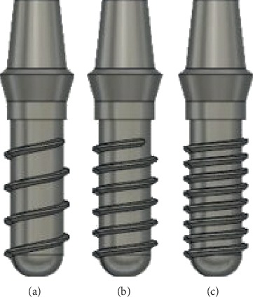
Configurations of implants with an abutment. (a) Single threaded 2.2 mm pitch. (b) Single threaded 1.4 mm pitch. (c) Single threaded 1 mm pitch.
Acknowledgments
We are grateful to the Department of Mechanical and Manufacturing Engineering, Manipal Institute of Technology, Manipal, for all the technical support during the conduct of the study.
Data Availability
The data used in this are available from the corresponding author upon request.
Conflicts of Interest
The authors declare that they have no conflicts of interest.
References
- 1.Amid R., Raoofi S., Kadkhodazadeh M., Movahhedi M. R., Khademiand M. Effect of micro thread design of dental implants on stress and strain patterns: a three-dimensional finite element analysis. Biomedizinische Technik/Biomedical Engineering. 2013;58(5):457–467. doi: 10.1515/bmt-2012-0108. [DOI] [PubMed] [Google Scholar]
- 2.Hermann F., Lerner H., Palti A. Factors influencing the preservation of the periimplant marginal bone. Implant Dentistry. 2007;16(2):165–175. doi: 10.1097/id.0b013e318065aa81. [DOI] [PubMed] [Google Scholar]
- 3.Steigenga J. T., Al-Shammari K. F., Nociti F. H., Misch C. E., Wang H.-L. Dental implant design and its relationship to long-term implant success. Implant Dentistry. 2003;12(4):306–317. doi: 10.1097/01.id.0000091140.76130.a1. [DOI] [PubMed] [Google Scholar]
- 4.Abuhussein H., Pagni G., Rebaudi A., Wangand H.-L. The effect of thread pattern upon implant osseointegration. Clinical Oral Implants Research. 2010;21(2):129–136. doi: 10.1111/j.1600-0501.2009.01800.x. [DOI] [PubMed] [Google Scholar]
- 5.Geng J. P., Xu W., Tan K. B. C., Liu G. R. Finite element analysis of an osseointegrated stepped screw dental implant. Journal of Oral Implantology. 2004;30(4):223–233. doi: 10.1563/0654.1. [DOI] [PubMed] [Google Scholar]
- 6.Flach M., Streckbein P. Finite element analysis of the bone remodelling process considering bone condensing around osseointegrated dental implants. Journal of Biomechanics. 2006;39:p. S454. doi: 10.1016/s0021-9290(06)84859-1. [DOI] [Google Scholar]
- 7.Ghanem W. A., Sadakah A. A. Effect of implant length on the stability and osseointegration of immediate implant. Egyptian Journal of Oral & Maxillofacial Surgery. 2016;7(2):41–48. doi: 10.1097/01.omx.0000481452.49607.ad. [DOI] [Google Scholar]
- 8.Anitua E., Piñas L., Begoña L., Orive G. Long-term retrospective evaluation of short implants in the posterior areas: clinical results after 10–12 years. Journal of Clinical Periodontology. 2014;41(4):404–411. doi: 10.1111/jcpe.12222. [DOI] [PubMed] [Google Scholar]
- 9.Negri B., Calvo Guirado J. L., Maté Sánchez de Val J. E., et al. Peri-implant tissue reactions to immediate nonocclusal loaded implants with different collar design: an experimental study in dogs. Clinical Oral Implants Research. 2014;25(2):e54–e63. doi: 10.1111/clr.12047. [DOI] [PubMed] [Google Scholar]
- 10.Fuh L., Huang H.-L., Chen M. Y. C., Shen Y.-W. Biomechanical investigation of thread designs and interface conditions of zirconia and titanium dental implants with bone: three-dimensional numeric analysis. International Journal of Oral & Maxillofacial Implants. 2013;28(2):e64–e71. doi: 10.11607/jomi.2131. [DOI] [PubMed] [Google Scholar]
- 11.Ormianer Z., Matalon S., Block J., Kohen J. Dental implant thread design and the consequences on long-term marginal bone loss. Implant Dentistry. 2016;25(4):471–477. doi: 10.1097/id.0000000000000441. [DOI] [PubMed] [Google Scholar]
- 12.Chowdhary R., Halldin A., Jimbo R., Wennerberg A. Influence of micro threads alteration on osseointegration and primary stability of implants: an FEA and in vivo analysis in rabbits. Clinical Implant Dentistry and Related Research. 2015;17(3):562–569. doi: 10.1111/cid.12143. [DOI] [PubMed] [Google Scholar]
- 13.Strickstrock M., Rothe H., Grohmann S., et al. Influence of surface roughness of dental zirconia implants on their mechanical stability, cell behavior and osseointegration. BioNanoMaterials. 2017;18(1-2) doi: 10.1515/bnm-2016-0013. [DOI] [Google Scholar]
- 14.Ong J. L., Chan D. C. N. Hydroxyapatite and their use as coatings in dental implants: a review. Critical Reviews™ in Biomedical Engineering. 2000;28(5):667–707. doi: 10.1615/critrevbiomedeng.v28.i56.10. [DOI] [PubMed] [Google Scholar]
- 15.Karacan I., Jacob Macha I., Choi G., Cazalbou S., Ben-Nissan B. Key Engineering Materials. Vol. 758. Stafa-Zurich, Switzerland: Trans Tech Publications Ltd; 2017. Antibiotic containing poly lactic acid/hydroxyapatite biocomposite coatings for dental implant applications; pp. 120–125. [Google Scholar]
- 16.Chen X., Chen S., Liang L., Hong H., Zhang Z., Shen B. Electrochemical behaviour of EPD synthesized graphene coating on titanium alloys for orthopedic implant application. Procedia CIRP. 2018;71:322–328. doi: 10.1016/j.procir.2018.05.035. [DOI] [Google Scholar]
- 17.Eraslan O., İnan Ö. The effect of thread design on stress distribution in a solid screw implant: a 3D finite element analysis. Clinical Oral Investigations. 2010;14(4):411–416. doi: 10.1007/s00784-009-0305-1. [DOI] [PubMed] [Google Scholar]
- 18.Bosshardt D. D., Chappuis V., Buser D. Osseointegration of titanium, titanium alloy and zirconia dental implants: current knowledge and open questions. Periodontology. 2000;73(1):22–40. doi: 10.1111/prd.12179. [DOI] [PubMed] [Google Scholar]
- 19.Baggi L., Cappelloni I., Di Girolamo M., Maceri F., Vairo G. The influence of implant diameter and length on stress distribution of osseointegrated implants related to crestal bone geometry: a three-dimensional finite element analysis. The Journal of Prosthetic Dentistry. 2008;100(6):422–431. doi: 10.1016/s0022-3913(08)60259-0. [DOI] [PubMed] [Google Scholar]
- 20.Aparna I. N., Dhanasekar B., Lingeshwar D., Gupta L. Implant crest module: a review of biomechanical considerations. Indian Journal of Dental Research. 2012;23(2):p. 257. doi: 10.4103/0970-9290.100437. [DOI] [PubMed] [Google Scholar]
- 21.Mehrali M., Seyed Shirazi F., Mehrali M., et al. Dental implants from functionally graded materials. Journal of Biomedical Materials Research Part A: An Official Journal of the Society for Biomaterials. 2013;101(10):3046–3057. doi: 10.1002/jbm.a.34588. [DOI] [PubMed] [Google Scholar]
- 22.Rahbar N., Soboyejo W. O. Design of functionally graded dental multilayers. Fatigue & Fracture of Engineering Materials & Structures. 2011;34(11):887–897. doi: 10.1111/j.1460-2695.2011.01581.x. [DOI] [Google Scholar]
- 23.Sadollah A., Bahreininejad A., Eskandar H., Hamdi M. Optimum material gradient for functionally graded dental implant using particle swarm optimization. Advanced Materials Research. 2013;647:30–36. doi: 10.4028/www.scientific.net/amr.647.30. [DOI] [Google Scholar]
- 24.Yang J., Xiang H.-J. A three-dimensional finite element study on the biomechanical behavior of an FGBM dental implant in surrounding bone. Journal of Biomechanics. 2007;40(11):2377–2385. doi: 10.1016/j.jbiomech.2006.11.019. [DOI] [PubMed] [Google Scholar]
- 25.Chen C.‐C., Huang T.‐H., Kao C.‐T., Ding S.‐J. Characterization of functionally graded hydroxyapatite/titanium composite coatings plasma‐sprayed on Ti alloys. Journal of Biomedical Materials Research Part B: Applied Biomaterials: An Official Journal of the Society for Biomaterials. 2006;78(1):146–152. doi: 10.1002/jbm.b.30465. [DOI] [PubMed] [Google Scholar]
- 26.Marrella A., Aiello M., Quarto R., Scaglione S. Chemical and morphological gradient scaffolds to mimic hierarchically complex tissues: from theoretical modeling to their fabrication. Biotechnology and Bioengineering. 2016;113(10):2286–2297. doi: 10.1002/bit.25994. [DOI] [PubMed] [Google Scholar]
- 27.Scaffaro R., Lopresti F., Maio A., Sutera F., Botta L. Development of polymeric functionally graded scaffolds: a brief review. Journal of Applied Biomaterials & Functional Materials. 2017;15(2):107–121. doi: 10.5301/jabfm.5000332. [DOI] [PubMed] [Google Scholar]
- 28.O’Mahony A. M., Williams J. L., Spencer P. Anisotropic elasticity of cortical and cancellous bone in the posterior mandible increases peri-implant stress and strain under oblique loading. Clinical Oral Implants Research. 2001;12(6):648–657. doi: 10.1034/j.1600-0501.2001.120614.x. [DOI] [PubMed] [Google Scholar]
- 29.İplikçioğlu H., Akça K. Comparative evaluation of the effect of diameter, length and number of implants supporting three-unit fixed partial prostheses on stress distribution in the bone. Journal of Dentistry. 2002;30(1):41–46. doi: 10.1016/s0300-5712(01)00057-4. [DOI] [PubMed] [Google Scholar]
- 30.Şimşek B., Erkmen E., Yilmaz D., Eser A. Effects of different inter-implant distances on the stress distribution around endosseous implants in posterior mandible: a 3D finite element analysis. Medical Engineering & Physics. 2006;28(3):199–213. doi: 10.1016/j.medengphy.2005.04.025. [DOI] [PubMed] [Google Scholar]
- 31.Patil V., Naik N. A comparative study on the effect of stress in dental implant structure using finite element analysis. International Journal of Mechanical and Production Engineering Research and Development. 2019;9(2):709–717. [Google Scholar]
- 32.Du Q., Zheng M., Zhang L., et al. Preparation of functionalized graphene sheets by a low-temperature thermal exfoliation approach and their electrochemical supercapacitive behaviors. Electrochimica Acta. 2010;55(12):3897–3903. doi: 10.1016/j.electacta.2010.01.089. [DOI] [Google Scholar]
- 33.Zhang Y., Nayak T. R., Hong H., Cai W. Graphene: a versatile nanoplatform for biomedical applications. Nanoscale. 2012;4(13):3833–3842. doi: 10.1039/c2nr31040f. [DOI] [PMC free article] [PubMed] [Google Scholar]
- 34.Rosa V., Xie H., Dubey N., et al. Graphene oxide-based substrate: physical and surface characterization, cytocompatibility and differentiation potential of dental pulp stem cells. Dental Materials. 2016;32(8):1019–1025. doi: 10.1016/j.dental.2016.05.008. [DOI] [PubMed] [Google Scholar]
- 35.Xie H., Cao T., Rodríguez-Lozano F. J., Luong-Van E. K., Rosa V. Graphene for the development of the next-generation of biocomposites for dental and medical applications. Dental Materials. 2017;33(7):765–774. doi: 10.1016/j.dental.2017.04.008. [DOI] [PubMed] [Google Scholar]
- 36.Marrella A., Tedeschi G., Giannoni P., et al. “Green-reduced” graphene oxide induces in vitro an enhanced biomimetic mineralization of polycaprolactone electrospun meshes. Materials Science and Engineering C. 2018;93:1044–1053. doi: 10.1016/j.msec.2018.08.052. [DOI] [PubMed] [Google Scholar]
- 37.Iyo T., Maki Y., Sasaki N., Nakata M. Anisotropic viscoelastic properties of cortical bone. Journal of Biomechanics. 2004;37(9):1433–1437. doi: 10.1016/j.jbiomech.2003.12.023. [DOI] [PubMed] [Google Scholar]
- 38.Sasaki N., Nakayama Y., Yoshikawa M., Enyo A. Stress relaxation function of bone and bone collagen. Journal of Biomechanics. 1993;26(12):1369–1376. doi: 10.1016/0021-9290(93)90088-v. [DOI] [PubMed] [Google Scholar]
- 39.Chang P.-K., Chen Y.-C., Huang C.-C., Lu W.-H., Chen Y.-C., Tsai H.-H. Distribution of micromotion in implants and alveolar bone with different thread profiles in immediate loading: a finite element study. International Journal of Oral & Maxillofacial Implants. 2012;27:p. 6. [PubMed] [Google Scholar]
- 40.Geng J.-P., Tan K. B. C., Liu G.-R. Application of finite element analysis in implant dentistry: a review of the literature. The Journal of Prosthetic Dentistry. 2001;85(6):585–598. doi: 10.1067/mpr.2001.115251. [DOI] [PubMed] [Google Scholar]
- 41.Meroueh K. A. Finite element analysis of partially edentulous mandible rehabilitated with an osteointegrated cylindrical implant. Oral Implantology. 1987;13 [PubMed] [Google Scholar]
- 42.William K. R., Watson C. J., Murphy W. M., Scottt J., Gregory M., Sinobad D. Finite element analysis of fixed prostheses attached to osseointegrated implants. Quintessence International. 1990;21:p. 7. [PubMed] [Google Scholar]
- 43.Cervino G., Romeo U., Lauritano F., et al. Fem and von mises analysis of OSSTEM dental implant structural components: evaluation of different direction dynamic loads. The Open Dentistry Journal. 2018;12(1):219–229. doi: 10.2174/1874210601812010219. [DOI] [PMC free article] [PubMed] [Google Scholar]
- 44.Ivanoff C.-J., Gröndahl K., Sennerby L., Bergström C., Lekholm U. Influence of variations in implant diameters: a 3-to 5-year retrospective clinical report. International Journal of Oral & Maxillofacial Implants. 1999;14:2. [PubMed] [Google Scholar]
- 45.Burr D. B., Forwood M. R., Martin R. B., et al. Bone microdamage and skeletal fragility in osteoporotic and stress fractures. Journal of Bone and Mineral Research. 1997;12(1):6–15. doi: 10.1359/jbmr.1997.12.1.6. [DOI] [PubMed] [Google Scholar]
- 46.Isidor F. Histological evaluation of peri-implant bone at implants subjected to occlusal overload or plaque accumulation. Clinical Oral Implants Research. 1997;8(1):1–9. doi: 10.1111/j.1600-0501.1997.tb00001.x. [DOI] [PubMed] [Google Scholar]
- 47.Kang Y.-I., Lee D.-W., Park K.-H., Moon I.-S. Effect of thread size on the implant neck area: preliminary results at 1 year of function. Clinical Oral Implants Research. 2012;23(10):1147–1151. doi: 10.1111/j.1600-0501.2011.02298.x. [DOI] [PubMed] [Google Scholar]
- 48.Kong L., Zhao Y., Hu K., et al. Selection of the implant thread pitch for optimal biomechanical properties: a three-dimensional finite element analysis. Advances in Engineering Software. 2009;40(7):474–478. doi: 10.1016/j.advengsoft.2008.08.003. [DOI] [Google Scholar]
- 49.Niinomi M. Recent research and development in titanium alloys for biomedical applications and healthcare goods. Science and Technology of Advanced Materials. 2003;4(5):445–454. doi: 10.1016/j.stam.2003.09.002. [DOI] [Google Scholar]
- 50.Satheesh K., Jayavel R. Synthesis and electrochemical properties of reduced graphene oxide via chemical reduction using thiourea as a reducing agent. Materials Letters. 2013;113:5–8. doi: 10.1016/j.matlet.2013.09.044. [DOI] [Google Scholar]
- 51.Rojas M. I., Leiva E. P. M. Density functional theory study of a graphene sheet modified with titanium in contact with different adsorbates. Physical Review B. 2007;76(15) doi: 10.1103/physrevb.76.155415.155415 [DOI] [Google Scholar]
- 52.Liu S., Zeng T. H., Hofmann M., et al. Antibacterial activity of graphite, graphite oxide, graphene oxide, and reduced graphene oxide: membrane and oxidative stress. ACS Nano. 2011;5(9):6971–6980. doi: 10.1021/nn202451x. [DOI] [PubMed] [Google Scholar]
- 53.La W.-G., Park S., Yoon H.-H., et al. Delivery of a therapeutic protein for bone regeneration from a substrate coated with graphene oxide. Small. 2013;9(23):4051–4060. doi: 10.1002/smll.201300571. [DOI] [PubMed] [Google Scholar]
- 54.Jung H. S., Lee T., Kwon I. K., et al. Surface modification of multipass caliber-rolled Ti alloy with dexamethasone-loaded graphene for dental applications. ACS Applied Materials & Interfaces. 2015;7(18):9598–9607. doi: 10.1021/acsami.5b03431. [DOI] [PubMed] [Google Scholar]
Associated Data
This section collects any data citations, data availability statements, or supplementary materials included in this article.
Data Availability Statement
The data used in this are available from the corresponding author upon request.