

Abstract
Directed-energy deposition (DED)-based additive manufacturing (AM) was explored for composite development using silicon (Si) and hydroxyapatite (HA) in Ti-6Al-4V (Ti64) matrix for articulating surfaces of load-bearing implants. Specifically, laser engineered net shaping (LENS™), a commercially available DED-based AM technique, was used to fabricate composites from premixed-feedstock powders. The AM’d composites proved to not only improve upon Ti64’s mechanical properties but also produced an in-situ Si-based tribofilm during tribological testing that minimized wear induced damage. Additionally, it was found that with the introduction of Si, titanium silicides and vanadium silicides were formed; allowing for 114% increased hardness, decreased coefficient of friction (COF) and a reduction of wear rate of 38.1% and 48.7%, respectively. The produced composites also displayed a positive shift in open-circuit potential (OCP) during linear wear, along with a reduction in the change of OCP from idle to linear wear conditions. Additionally, contact resistance (CR) values increased with a maximum value of 1500 ohms due to the formation of Si-based tribofilm on the wear surface. Such composite development approach using DED-based AM can open up the possibilities of innovating next-generation implants that are designed and manufactured via multi-material AM.
Keywords: Load-bearing implants, Ti6Al4V, bio-tribocorrosion, hydroxyapatite-Si composite, tribofilm, surface modification, directed-energy deposition
1.0. Introduction
One in seven Americans suffer from musculoskeletal disorders requiring arthroplasty [1]. Specifically, total knee arthroplasty (TKA) and total hip arthroplasty (THA) have become common surgical procedures for restoration of joint functionality – with CoCrMo being the metallic material most commonly used in load-bearing articulating surfaces [2], [3]. Additionally, implant modularity has become common in modern hip implants; the reason is for the increased ease of implantation as well as exact reconstruction and replication of biomechanical motions. In part, this is due to the improved combination of limb length, anteversion and offset angle [4]. Although, on the contrary, implant modularity has also been reported to cause premature implant failure by means of taper corrosion [5]. Micro vibrations between two coupled surfaces occur during normal gait motion allowing for what is specifically referred to as fretting corrosion to take place – although it is not the focus of the current work [6], [7]. Additionally, an electrochemical potential difference exists when coupling, for example, a CoCrMo femoral head with a Ti64 hip stem; this is currently done in the orthopedic device manufacturing industry and accounts for taper corrosion failure due to galvanic corrosion [8]. Wear induced leaching of CoCrMo particles also cause issues as the increased surface-to-volume ratio amplifies the dissolution of the material into Co2+ and Cr3+ ions when in contact with the biological environment. As a result, aggressive corrosion takes place and is facilitated in part by the physiological environment i.e., water, oxygen, proteins, and enzymes [9]. Adverse effects can arise as both Co2+ and Cr3+ ions are toxic in the body or alter the normal physiological activity [10], [11]. The presence of these ions in the local physiological environment has been reported to cause aseptic loosening by increasing bone-resorbing mediator activity as well as tissue death [5], [12]–[15]. Adding to the issue, anytime the natural joint is replaced, there is a change in the tribological environment. The implanted material falls short as it has the inability to produce a permanent artificial lubricating film [16], thus allowing for increased wear, debris release and removal of the passive film [17]. Therefore, to reduce the drive for galvanic corrosion, decrease the release of toxic ions into the physiological environment and form a lubricating film on the articulating surface, it would be advantageous for the femoral head and hip stem to be of similar materials with the added ability for the material experiencing wear to form a permanent artificial lubricating film. Our approach is to use titanium (Ti) as the bulk material and apply the composite compositions as a coating fabrication with reinforcements allowing for increased wear resistance as well as allowing for tribofilm formation to minimize overall wear. However, to achieve this goal, Ti’s mechanical properties need to be improved upon.
Several techniques have been implemented with the objective of improving the mechanical and chemical properties of Ti alloys. Among the various Ti alloys, Ti64 is the most widely used alloy for biomedical device applications such as screws, plates, hip stems, etc. However, Ti64 suffers from poor wear resistance when compared to other biomedical-grade alloys such as the previously mentioned CoCrMo alloy [18], [19]. This is due to the low resistance to plastic shear and work hardening exhibited by Ti. It is also the main reason why Ti and its’ alloys are not primarily used in any articulating surfaces of load-bearing implants [20]. Several techniques exist to reduce material degradation and ion release, one such being surface hardening. Several methods exist to increase the surface hardness of metals such as nitriding [21], work hardening [22], precipitate hardening [23], [24], martensitic transformation [25] and solid solution strengthening [26]. Specifically, for improving Ti and its alloy’s mechanical and chemical properties, work has been done with the use of Si. It has been reported that small addition of Si into Ti alloys improved their fatigue resistance such as addition in Ti3Al [27], γ-titanium aluminides [28] and Ti-6Al-5Zr-1W-0.4Si [29]. Further methods for improving the wear resistance of materials has been done using solid lubricants. Solid lubricants in a tribo-system refer to a functional material that allows for a significant reduction in friction force of a sliding interface [30]. The mechanism works by the production of a tribofilm, where the produced tribofilm is identified as a thin film produced by the action of sliding contact and is adhered to the worn parent surface [30], [31]. Tribofilm formation has been reported in laser engineered net shaping (LENS™) processed CoCrMo or Ti and calcium phosphate (CaP) composites [32]–[34], aluminum-silicon discs lubricated by zinc dialkyldithiophosphate solution [35] and in electron-beam-evaporation produced gold-zinc oxide thin films [36], just to name a few.
Thus, acknowledging that Ti’s mechanical and chemical properties can be improved with CaP and Si introduction into the Ti matrix, in this present study, Ti64 metal-matrix composites with varying Si and Si/HA content were fabricated using LENS™-based AM. LENS™ technique was chosen as the build process can be done under a controlled environment. The ability to purge oxygen and replace it with inert argon within the build chamber highly minimizes undesired side-reaction products. Additionally, DED-base additive manufacturing has allowed us to fabricate an exotic combination composite alloy with a fraction of the energy requirement as needed for other manufacturing techniques; with the inherent trait of DED – material efficiency. Minimal material loss is seen in the form of material removal in postprocessing as the DED technique produces a near-net-shape part; Si, HA, and Ti64 are processed without the bulky and inefficient equipment needed traditionally. A mixture of the three materials was used as the feedstock powder for the work and allowed for in situ-reactive deposition of the material – something not do-able through any other form of manufacturing process. The produced samples at this scale were then tested and promising results concluded from the study as seen in the processing and results walk-though depicted in Fig. 1.
Figure 1.

Flowchart comprising of fabrication, methodology and key results of the DED-based AM-processed composites
The objective of the present study was to understand the influence of Si and HA on the bio-tribocorrosion and mechanical properties of Ti64. It was hypothesized that Ti64’s wear and corrosion resistance would increase due to in situ-reactive deposition reinforcements produced and in situ tribofilm formation during linear wear testing. To understand the effect Si and HA have on Ti64, microstructural examination, phase analysis, hardness, bio-tribocorrosion testing, as well as in situ acquisition of contact resistance (CR) and open-circuit potential (OCP) were performed. Minimal work has been reported for in situ tribofilm formation by instantaneous CR acquisition and equilibrium potential for a tribological system comprising of both Si and HA in the Ti64 matrix. Additionally, the composites were fabricated by DED-based AM to address the current issues associated with CoCrMo based-hip implants.
2.0. Materials and methods
2.1. Sample fabrication:
Ti64 powder was purchased from Crucible Research (Pittsburgh, PA). Si powder was purchased from SIGMA-ALDRICH (99% trace metals) and hydroxyapatite (HA) powder was purchased from Berkeley Advanced Biomaterials, Inc. (CA, USA). Powders were sieved to a particle size distribution of 49 – 145 μm. LENS™ processed samples were of pure Ti-6Al-4V (Ti64), Ti64 + 5 wt.% Si (5Si), Ti64 + 10 wt.% Si (10Si) and Ti64 + 3 wt.% Si + 2 wt.% HA (T32). Feedstock powders were mixed by ball milling for 1h at 40 rpm in a container with a diameter of ~62 mm. No milling media was used. Samples were fabricated using a commercial LENS™ system (Optomec Inc. Albuquerque, NM) equipped with a 500 W continuous-wave Nd: YAG laser beam. All build parameters are displayed in Table 1. All compositions were deposited as coatings on commercially available Ti64 substrate. Energy density values were calulated by the commonly used volumetic energy density equation, as reported by España [37].
Table 1.
LENS™ processing parameters for control and composite samples and calculated energy density values.
| Sample | Laser Power (W) | Powder Feed Rate (g/min) | Hatch/Contour Beam Speed (mm/s) | Sample Dimensions (mm) | Hatch Spacing (mm) | Layer Thickness (mm) | Energy Density (J/mm3) |
|---|---|---|---|---|---|---|---|
| Ti64 | 350 | 12 | 12.7/12.7 | 12 × 14 | 0.5 | 0.55 | 100.2 |
| 5Si | 330 | 94.5 | |||||
| 10Si | 300 | 15 | 86.0 | ||||
| T32 | 380 | 13 | 108.8 |
2.2. Hardness and microstructure:
Post-DED fabricated samples were mounted in phenolic thermoset resin. Sample grinding was done using 80, 120, 320, 600, 800, 1000 and 2000 grit SiC grinding papers. Samples were then polished with suspended alumina solution having particle size of 0.3 μm. After polishing, samples were ultrasonically cleaned in 200 proof ethanol. Microhardness was performed with the use of a Phase II Plus, Micro Vickers hardness tester (Upper Saddle River, NJ, USA). Loading was 200 g, dwell time of 15 s and six indents per sample. Acid etching for revealing microstructural features was carried out by use of Kroll’s Reagent (46 ml DI water, 3 ml nitric acid, 1 ml hydrofluoric acid) by submersion for 15 s. Both after polishing and etching, samples were rinsed in DI water, ultrasonically cleaned in 200 proof ethanol and allowed to dry. Secondary electron micrographs and elemental analysis (EDS) images were attained using a field emission scanning electron microscope (FESEM, FEISIRION, Portland, OR).
2.3. Phase analysis:
Using a PANalytical X’pert Pro MPD XRD machine (The Netherlands), X-ray diffraction (XRD) measurements were performed. X-ray source was Cu-Kα radiation (1.54 Å) at 45 kV and 40 mA, scanning from 2θ values of 30 to 80 degrees at a step size of 0.05 2θ and 6 s dwell time. Peak identification of α-Ti (hexagonal), Si (cubic), Ti5Si3 (hexagonal), TiSi2 (orthorhombic) and V5Si3 (tetragonal) for LENS™ processed samples was done using reference cards from the International Centre for Diffraction Data (ICDD). Reference cards are as follows: ICDD:98-004-3416, ICDD:98-005-3783, ICDD:98-006-2591, ICDD:98-009-6029 and ICDD:98-065-2495 for α-Ti, Si, Ti5Si3, TiSi2 and V5Si3, respectively. HA weight percent in T32 composition appeared to be below the detectable limits, therefore no reference card is reported for HA.
2.4. Bio-tribological analysis:
Tribological testing was performed using a single station Biotribometer (Ducom, Bangalore, India) following ASTM G133–05 standard [38] – the standard for ball-on-flat linear reciprocating testing. Final wear rate calculations were done in accordance with this standard – that is measurement of the final wear track width and normalized by load and total linear travel. The applied normal load was 5 N, translation speed was 1200 mm/min and amplitude of 10 mm for a total sliding distance of 1000 m in DI water. The counter material for reporting COF, compound wear (CW) and open circuit potential (OCP) was a 3 mm silicon nitride (Si3N4) wear ball, while a hardened chrome steel ball (Boca Bearing, Boynton Beach, FL, USA) was used for CR data acquisition. CW was logged by z-axis displacement and CR was acquired by a 2-wire circuit with a known current, as displayed in Fig. 2. Biotribocorrosion testing was conducted with the use of a modular line Metrohm Autolab potentiostat/galvanostat (Riverview, Florida, USA), with a 3-electrode corrosion-cell configuration. The reference electrode was saturated Ag/AgCl/KCl, counter electrode was of platinum and the working electrode were the fabricated samples of the varying compositions for each respective test. The electrolyte media used was Dulbecco’s Modified Eagle’s Medium (DMEM)/nutrient mixture F-12 Ham (with L-glutamine and 15 mM HEPES, without sodium bicarbonate, Sigma-Aldrich). Once submerged in the DMEM, the samples were allowed to idle 1 h prior to linear wear testing is started. Dynamic conditions are most pertinent to articulating load-bearing applications.
Figure 2.

Schematic representation of apparatus used for bio-tribological testing in DMEM of LENS™ processed samples.
2.5. Statistical details:
Statistical analysis was done for COF, normalized wear rates, and hardness values. Tribological testing was conducted at least three times for each composition. Reported averages for COF and normalized wear rate are based on the pooled average (n=3). Reported hardness values are averaged from six indents per sample of three samples total for each composition. ANOVA testing was first performed across all the compositions’ averages to maintain the α = 0.05 significance value protection. If a difference in means resulted, pair-wise student t-testing was done to find the difference in means.
3.0. Results
LENS™ was used to produce Si and HA reinforced Ti64 matrix composites. To understand the influence of the two aforementioned constituents on Ti64, microstructural evaluation, bio-tribological studies and assessment of mechanical properties were conducted.
3.1. Phase analysis, microstructure, and hardness:
LENS™-processed Ti64 exhibited only characteristic α-Ti peaks in the XRD spectra as shown in Fig. 3, and corresponding acicular α-Ti grains can be seen in Fig. 4a. With the addition of Si, the first 5Si composite reveals the presence of titanium silicide (Ti5Si3). Present in the initial deposition layer appears to be intergranular Si. Upon further addition of Si – the second 10Si composite’s XRD spectrum reveals characteristic 2θ peaks for the formation of titanium disilicide (TiSi2), vanadium silicide (V5Si3), and the presence of Ti5Si3 as well. In addition, elemental crystalline Si is also observed in the 10Si composite. Finally, with the addition of HA, the T32 composite displays a similar spectrum to that of 5Si but appears to stabilize α-Ti over the formation of Ti5Si3. When comparing 5Si and T32 spectrums, peaks appear to have narrowed for T32, discernment between α-Ti (011) and Ti5Si3 (121) peaks can be made; possibly due to a reduction of thermally induced stresses allowed by the HA presence in the feedstock powder during the fabrication process.
Figure 3.
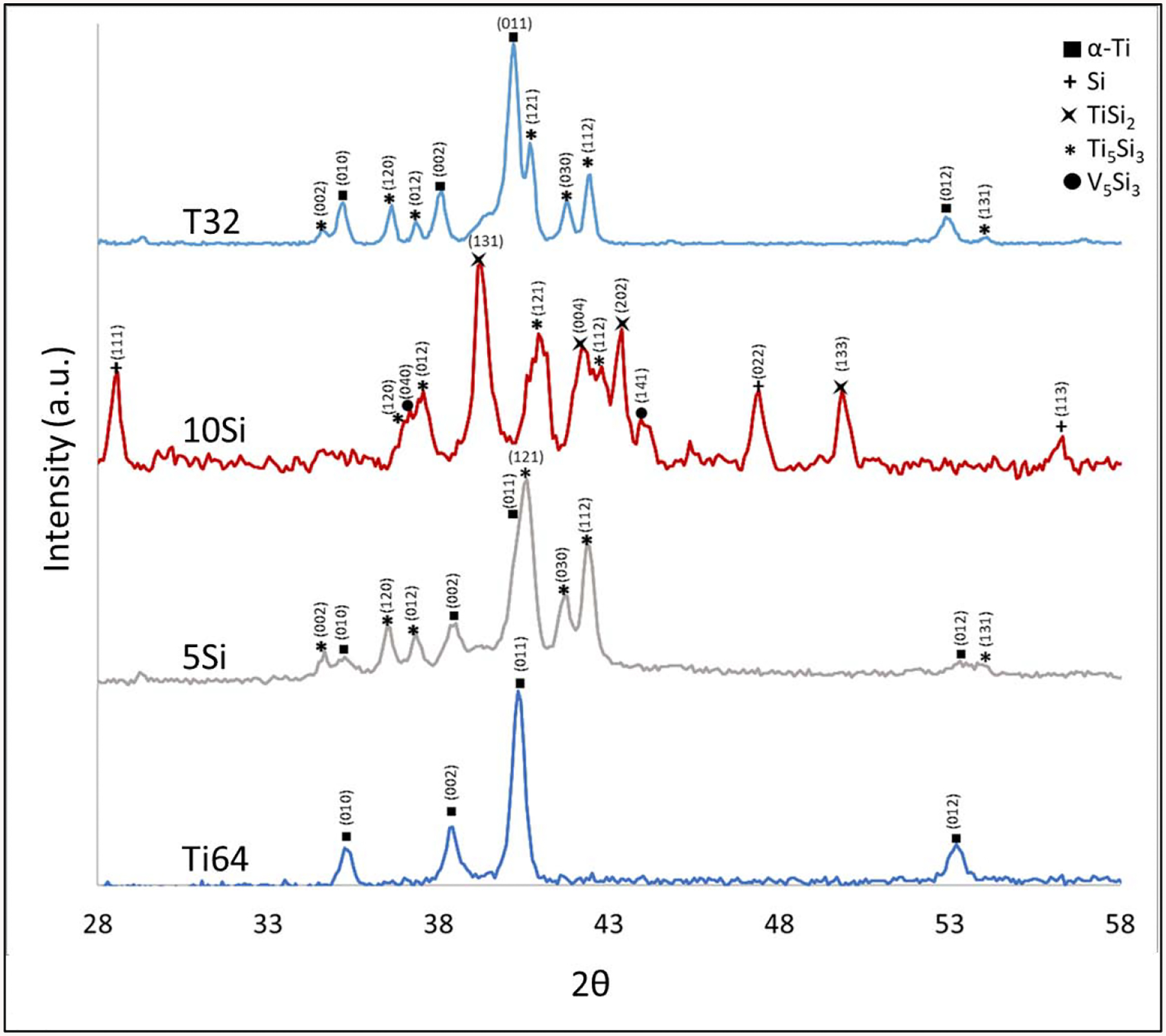
XRD spectrum for LENS™ processed compositions.
Figure 4.
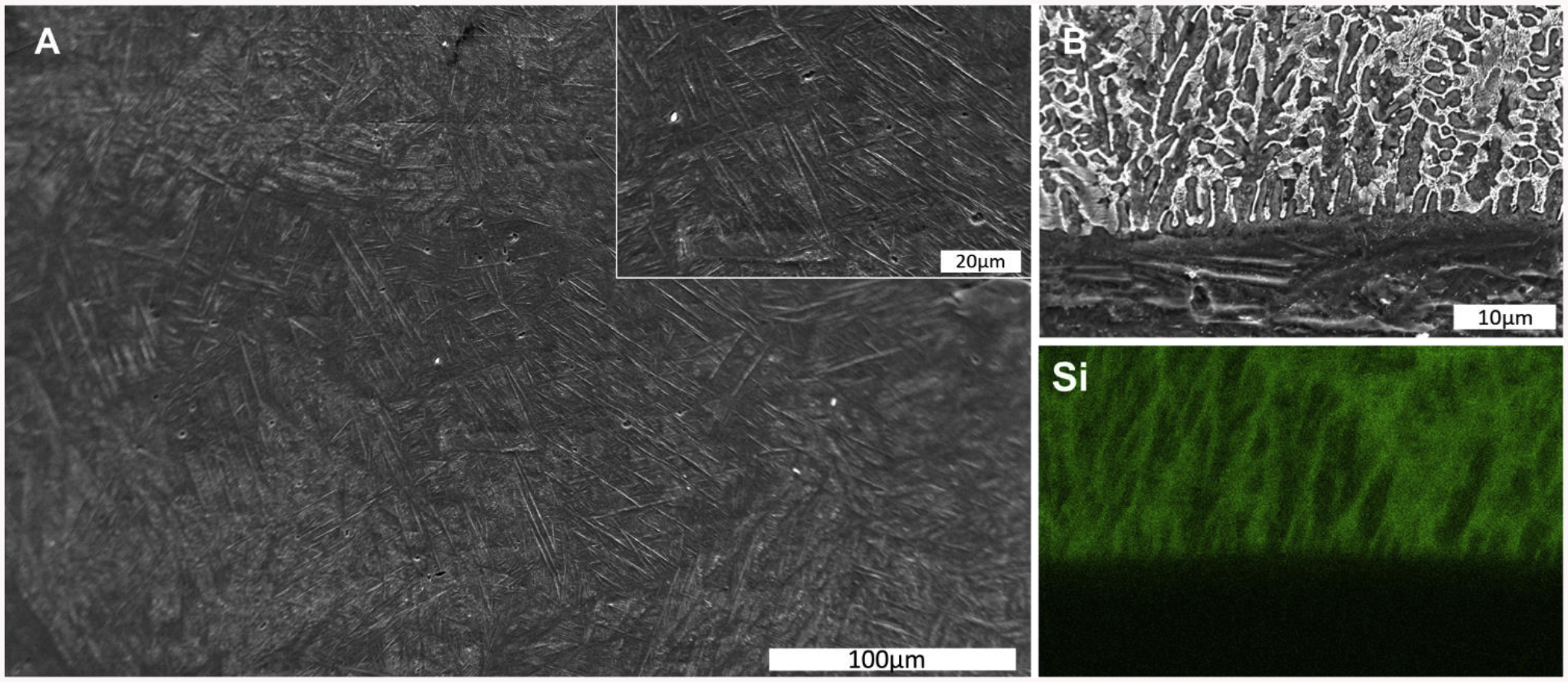
Etched cross-sectional sample surface of as-processed, a) Ti64 sample – displaying acicular α-Ti and b) 5Si composite sample – displaying intergranular Si presence along the first layer of deposition along with its respective elemental Si map.
Electron micrographs for 10Si reveal a structurally graded microstructure, as shown in Fig. 5. The Ti64 substrate microstructure consists of α-β Ti, which is typical considering Al is an α-Ti phase stabilizer, while V stabilizes the β-Ti phase. Along the interface, acicular α-Ti is present as well as elemental Si. Further away than 50 μm into the coating, silicides become the predominant structural feature with increasing intensity and agglomeration at >200 μm into the coating. With the addition of HA, T32 displayed a similar microstructure as 10Si near the interface, some Ti64 particles along with minimal micropores were observed in the T32 composite sample. For T32, this region is due to unreacted Si but also due to the presence of HA. The microstructural variation observed in 10Si is absent in T32, and minimal silicide formation is observed. Therefore, it appears that the presence of HA improved the homogeneity of the microstructure.
Figure 5.

Micrographs for interface cross-sections of 10Si and T32 composites after acid etching.
Surface hardness for Ti64 substrate, LENS™ processed Ti64, 5Si, 10Si, and T32 compositions are 162.2 ± 8.8, 393.9 ± 7.1, 632.6 ± 58.0, 844.9 ± 53.6, and 802.2 ± 10.9 HV0.2, respectively. Statistical difference (p<0.001) in means is observed amongst all pair-wise comparisons except when comparing 10Si to T32, in where the p-value was 0.09. The hardness of LENS™ processed Ti64 is greater than that of the Ti64 substrate – a possible result of the metastable acicular α-Ti phase present in the Ti64 composition after LENS™ processing. With Si addition, hardness increased by approximately 240 HV0.2 or about 60% for 5Si. With the further addition of Si, hardness for the composition 10Si increased by 114% when compared to Ti64. Composition T32’s hardness increased to 103% and 26.8% when compared to Ti64 and 5Si, respectively. When comparing composition 5Si with T32, both compositions have 5 wt.% foreign material in the Ti64 matrix, but T32 displayed a statistically significant (p=0.0003) increase in hardness of 26.8% over 5Si.
3.2. Bio-tribological testing:
Fig. 6 displays tribological data for all samples. Composition Ti64 displayed the highest amount of final compound wear (CW) at 162 μm, as seen in Fig. 6a. Compositions 5Si, 10Si and T32 had a final CW of 124, 89 and 91 μm, respectively. When compared to Ti64: 5Si, 10Si, and T32 displayed a 23.5%, 45.1%, and 43.8% decrease in final CW, respectively. Composition T32’s final CW was similar to 10Si but did display a reduced running-in wear regime within the first 200 m of testing, as seen in Fig. 6a. Final normalized wear rate, calculated in accordance with ASTM G133–05 [38], for Ti64, 5Si, 10Si and T32 were 3.22×10⁻⁴ ± 1.1×10⁻⁵ mm3/Nm, 2.67×10⁻⁴ ± 0.5×10⁻⁵ mm3/Nm, 0.94×10⁻⁴ ± 0.7×10⁻⁵ mm3/Nm, and 1.37×10⁻⁴ ± 0.6×10⁻⁵ mm3/Nm respectively. Statistical difference (p˂0.001) in means is observed amongst all pairwise comparisons, as displayed in Fig. 6b. Compared to Ti64, 5Si, 10Si, and T32 displayed a final normalized wear rate decrease of 17.2%, 70.8%, and 57.5%, respectively.
Figure 6.

Tribological data attained from Ducom Biotribometer: a) compound wear curve, b) final normalized wear rate calculated from measuring wear track width, c) coefficient of friction, d) average coefficient of friction (500 – 1000 m). Significance (p-value ˂0.001) displayed by an asterisk.
Their respective calculated wear coefficients from experimental data are also displayed in Table 2; Ti64, 5Si, 10Si, and T32’s calculated wear coefficients were 1.24×10⁻⁶, 1.65×10⁻⁶, 7.76×10⁻⁷, and 1.07×10⁻⁶, respectively. A dimensionless coefficient as it is work (Nm) normalized by work. With the exception of 5Si’s wear coefficient, there is an inverse relationship with reinforcement wt.% increase and calculated wear coefficient. The COF decreased for Si and HA composite samples, as seen in Fig. 6c and 6d. Attaining an average COF for the steady-state wear regime (500 – 1000 m), the COF for Ti64, 5Si, 10Si and T32 were 1.34 ± 0.05, 0.88 ± 0.04 and 0.83 ± 0.01 and 0.82 ± 0.01, respectively. That is a reduction of 34.3%, 38.1% and 38.8% for 5Si, 10Si, and T32, respectively, when compared to Ti64. All composite samples displayed a statistically significant decrease in COF compared to the Ti64 and amongst pairwise comparison except for the pairwise comparison of 10Si and T32.
Table 2.
Hardness (H) and wear volume (V) for the four DED fabricated samples for values wear coefficient calculation. Normal load (W) was 5N and sliding distance (S) was 1000 m for all testing.
| Ti64 | 5Si | 10Si | T32 | |
|---|---|---|---|---|
| Hardness (GPa) | 3.86 | 6.20 | 8.29 | 7.87 |
| Volume (m3) | 1.61×10⁻⁹ | 1.33×10⁻⁹ | 4.68×10⁻¹⁰ | 7.87×10⁻¹⁰ |
| Wear Coefficient (k) | 1.24×10⁻⁶ | 1.65×10⁻⁶ | 7.76×10⁻⁷ | 1.07×10⁻⁶ |
Contact resistance (CR) values were also acquired during tribological testing and are presented in Fig. 7. CR is representative of the resistance at the contact interface of the conductive wear ball and coating. In Fig. 7 inset, it can be seen that Ti64 remains at ~ 7 ohms for the entirety of the test. This can be interpreted as the baseline expected resistance of the circuit. CR for composition 5Si displays similar values as Ti64 up to ~ 150 m when an increase to ~ 20 – 80 ohms is observed and remains within this range up to 900 m; this can be due to slight passivation of the surface during linear wear. CR for the 10Si is seen to immediately commence at ~ 60 ohms and then fluctuate from 25 – 80 ohms; this fluctuation is observed until ~ 650 m – possibly resulting from the increased ceramic nature of the composition. Continually, CR is then seen to fluctuate from 20 – 600 ohms in the 650 – 800 m interval. At 800 m a steady increase is seen to ~ 1400 ohms and remains until 1000 m. It appeared that complete surface passivation occurred at this instance. Composition T32 exhibited a higher initial CR than 10Si and remained greater than 5Si, but with greater fluctuation. When compared to 5Si, it appears that HA accounted for the quicker surface passivation and hence quicker solid-based lubrication of the surface.
Figure 7.

Instantaneous contact resistance (CR) acquired through conductive counter wear ball and two-wire circuit ohm measurement, as displayed in Figure 2. The inset is used to display Ti64 CR values thoughtout testing (~7ohms).
Bio-tribocorrosion testing was conducted for the acquisition of the equilibrium potential under idle and linear mechanical wear conditions, displayed in Fig. 8. Under idle conditions, 10Si is most anodic and Ti64 is most cathodic. Under linear wear, Ti64 and 10Si exhibit similar OCP values, with T32 and 5Si displaying a positive shift of ~56 mV and ~90 mV when compared to 10Si, respectively. Under linear wear conditions, 5Si is the most cathodic but 10Si displayed the lowest ΔE values amongst the tested compositions. Once again, 10Si displaying a more ceramic nature as its OCP fluctuation was the lowest amongst the compositions.
Figure 8.

Open-circuit potential curves for compositions under idle (0–1 h), linear mechanical wear (1–2 h) and recovery period (2–3.5 h) in DMEM using Si3N4 counter material.
3.3. Wear track morphology and elemental mapping:
SEM and EDS micrographs were attained for the wear track surfaces and are presented in Fig. 9. The Ti64 surface is abrasive in appearance as seen in Fig. 9a1 and 9a2. Plastic deformation of the material is observed throughout the wear track as well as grooves in the central region. Removal and deposition of material are most observable at the wear track ends. Upon addition of Si, 5Si composition lacks the deposition of material at the end of the wear track and grooves at the central track region. Instead, it appears the initial material removal has been smeared over the surface; this could have occurred during the running-in wear regime. With 10Si composition, a reduction in the material layering is observed, greatly reduced grooves and a continuous film appears to cover the surface. Composition T32’s wear track also lacks the abrasive wear morphology at its end, and grooves in the center of the wear track. When compared to 5Si’s wear track, similar material smearing is present at the center of wear track for T32 but not as severe as is observed in 5Si. Upon elemental mapping of T32, Si-based superficial film presence can be determined.
Figure 9.
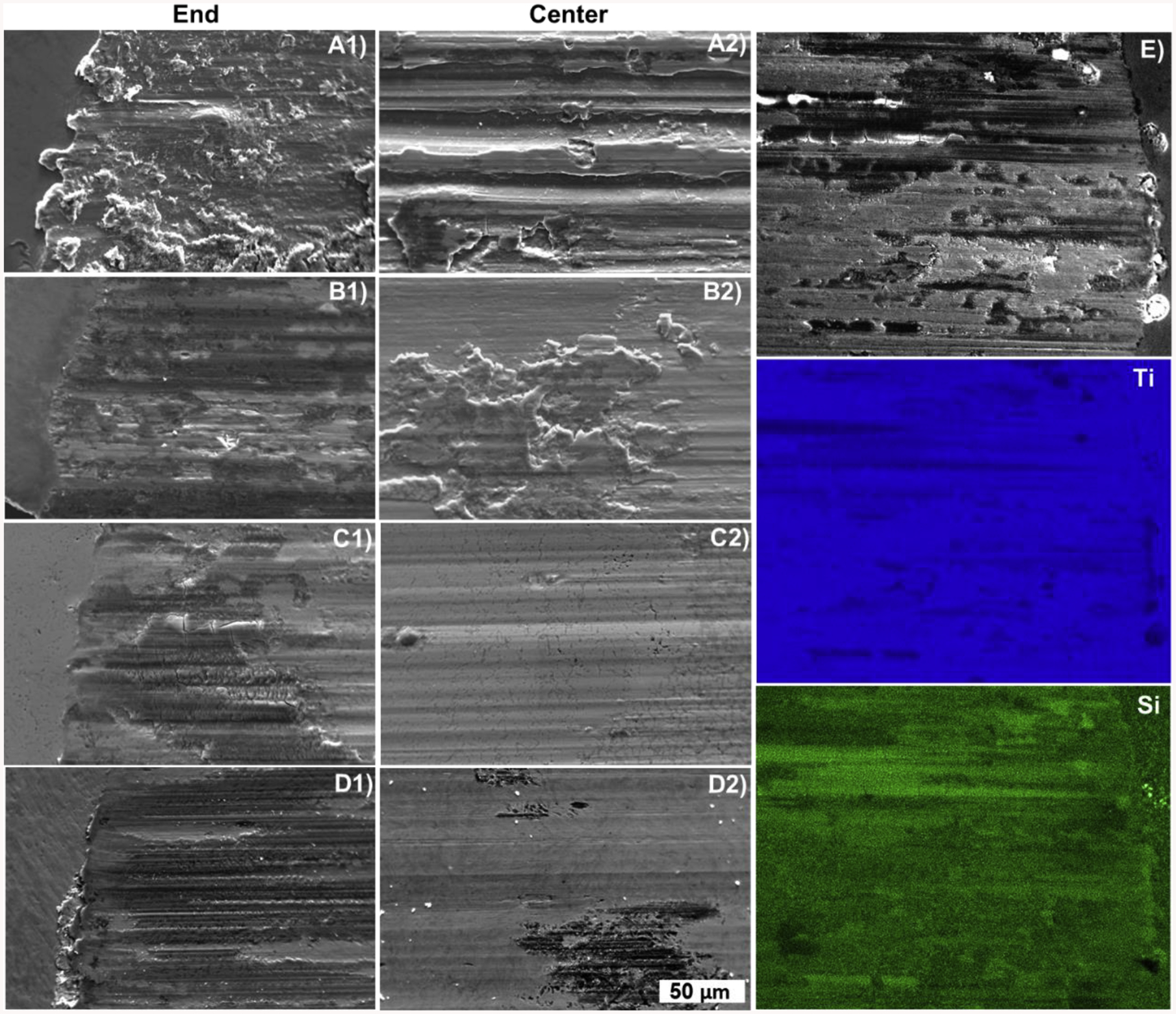
Secondary electron micrograph of wear track surface topography for as-built samples after tribological testing. A) Ti64, B) 5Si, C) 10Si and D) T32. E) Elemental mapping of Ti and Si of adjacent wear track end by EDS for T32.
4.0. Discussion
4.1. Phase analysis, microstructure, and hardness:
Phase analysis of composition Ti64 revealed only the presence of α-Ti. Relative peak broadening observed in the XRD spectrum is a result of lattice distortion and peak overlap resulting in peak augmentation [39]. Referring to Fig. 4, a homogenous needle-like microstructure is present on the etched surface of Ti64. As the melt is cooled and nucleation/solidification occurs, β-Ti grains form [40], [41]. These are larger and typically equiaxed grains. Upon further cooling, there is a solid-state phase change of β to α-Ti [42]. For pure Ti, the transition from α- to β-phase, when heating, occurs at ~880°C. Meta-stable phases with a strained lattice may be ‘trapped’ with fast cooling rates. In LENS™ operation, cooling rates tend to be large in magnitude, typically on the order of 103 K/s [23]. These fast cooling rates can prevent or restrict vanadium from diffusing out of the β-Ti’s bcc crystal structure, as a result, a full transition to α-Ti’s hcp crystal structure does not occur and thus results in the previously mentioned strained crystal structure [41]. The observable microstructure is most commonly referred to as acicular α-Ti or α’-Ti and has previously been reported in similar LENS™ and selective laser melting (SLM) related research [43], [44].
With the presence of Si, 5Si displayed the formation of Ti5Si3. The reaction 5Ti + 3Si → Ti5Si3 is exothermic, displaying a heat of formation of −579.5 kJ/mol and specific heat of 270.5 J/mol K [45]. The combination of relatively small heat capacity and large heat of formation classifies the reaction as a self-propagating high-temperature synthesis reaction [45], therefore silicide formation is favorable under LENS™ processing condition and is observed in the XRD data. Although, with the initial layer experiencing the fastest cooling rates, unreacted intergranular Si is present. In our case, the first deposition layer exhibits the fastest cooling rates due to substrate quenching. Upon further increase in Si content, 10Si composition displayed the formation of TiSi2 and V5Si3 as well as Ti5Si3. The heat of formation and heat capacity of V5Si3 is −462.3 kJ/mol and 362.3 J/mol K and for TiSi2 −133.9 kJ/mol and 21.0 J/mol K, respectively [45], [46]. The increase of formed silicides can be due to the combination of increased Si in the feedstock powder, and exothermic characteristics of the reactions taking place. An additional explanation can be due to the buffering characteristic of the first deposited layer from substrate quenching, thus allowing for increased ceramic formation. With the initial layer acting as a thermal buffer, heat is retained in the build material allowing for increased diffusion and reaction of Si with the constituents of Ti64 for the formation of different silicides. Microstructural variations in 10Si, Fig. 5, exist due to the presence of the temperature gradient is common with any directed energy laser process. It appears that 10Si was most affected by this gradient, possibly due to the increased Si presence in the feedstock powder and in situ formation of silicides. Ti has a heat capacity of 25.1 J/mol K, while Ti5Si3 exhibits approximately 10 times this heat capacity. Upon the formation of Ti5Si3, the formed ceramic would retain more thermal energy. Additionally, it is also known that peak melt pool temperature increases with ceramic formation, as ceramics have a higher laser absorption coefficient when compared to metals.
While Si addition increased silicide presence for 5Si and 10Si, T32’s phases analysis revealed that HA presence stabilized α-Ti and reduced peak-broadening. Both statements hold true when comparing their respective XRD data. T32, which also has 5 wt.% foreign material, when compared to 5Si displayed greater relative α-Ti peaks. Apart from α-Ti stabilization, the observed microstructure was more homogenous in the build direction. This can be indicative of a reduced thermal gradient after the initial layer deposition. Knowing that ceramics have a higher laser absorption coefficient, T32 had HA present in the feedstock powder allowing for it to behave as a thermal buffer, similar to composition 10Si. Additionally, some Ti64 particles along with a micropore were observed in the T32 composite sample.
The observed variation in phases and microstructure would also give rise to variations in hardness. An increase in hardness from the substrate to Ti64 is due to the acicular α-Ti. The increase in hardness for 5Si and 10Si from control Ti64 is due to the increased formation of silicides, which are Ti5Si3, V5Si3, and TiSi2 present in 10Si. T32 displayed an increase in hardness, ~170 HV0.2 when compared to 5Si. Statistically speaking, T32 and 10Si displayed no significant difference in hardness but a statistical difference is observed when comparing T32 to 5Si. Giving rise to the statement that a 2 wt.% HA addition into Ti64 had a more significant effect on hardness than a 7 wt.% Si addition alone. It appears that HA allowing for microstructure homogeneity also synergistically allowed for the increase in hardness.
4.2. Tribological analysis:
Compound wear is seen to reduce for all composites when compared to Ti64, with 10Si and T32 displaying similar compound wear curves. The increase in hardness can account for these reported curves as seen in Fig. 6a. Ceramics are harder and subsequently, the composite samples will also increase in hardness, and an overall reduction of wear is expected. Additionally, their respective calculated final wear rate was considerably lower, as demonstrated in Fig. 6b. T32’s final wear rate was lower than 5Si, even though both composites were processed from premixed feedstock powders with a similar 5 wt. % reinforcement. T32 displayed a 57.5% drop in wear rate while 5Si only displayed a 17.2%. The reduction in wear rate can be solely due to the HA acting as a solid lubricant. The COF for 5Si, 10Si, and T32 was relatively similar, this leads to conclude that interacting with the Si3N4 wear ball, a minimum of 5wt.% reinforcement is sufficed for a reduction of COF to ~0.8. In considering CR data, Ti64 lacked the formation of a non-conductive (passive) layer as there was no increase in CR, observed in Fig. 7. CR values for Si and HA composites increased and fluctuated when compared to Ti64. Fluctuations in CR can be interpreted as formation and removal of or ‘spotty’ non-continuous tribofilm. T32 increased the most initially, meaning the early formation of a tribofilm, but not as a mature or continuous as seen in 10Si, which exhibited the greatest increase with a constant value of CR.
Generally, a material’s wear resistance is in majority dependent on the hardness of the material, and can typically be estimated with the use of the Archard equation. Where the underlying theory of the equation is that a harder material will exhibit a lower wear rate [47]. However, this original equation doesn’t hold true for elastic/pseudoelastic materials. However, a modified equation is available to address this concern [48]. Although, complications in predicting a materials wear resistance with even the modified Archard equation arise as it does not account for a tribologically transformed structure (TTS) forming on the surface or for dynamic changes in the mechanical properties [49]. The TTS or tribofilm, in our case, is produced by the action of sliding contact, is adhered to the worn parent surface and differs in mechanical properties than that of the starting material [31], [32]. The occurrence of a TTS adds to the complexity to estimate a material’s wear resistance when experimental data is not present. Our present work is experimental. Therefore, the direct calculation of the wear coefficient present in the modified Archard equation can only be done based on our experimental data. It should be mentioned that this calculated wear coefficient is indicative of an average of the complete test and not at any specific time point throughout testing. Solving for the wear coefficient (k), the Archard equation is as follows:
Where V is the wear volume, W is the normal load and S is the sliding distance [48]. In this form, a larger k accounts for ‘severe’ wear whereas a smaller k accounts for ‘mild’ wear. The calculation of k was done for the fabricated samples and is displayed in Table 2. When done so, it was deemed that although the 5Si composition exhibited an increase in hardness and a decrease in wear volume/rate, the 5Si composition exhibited less wear resistance than the control Ti64. Instead, at the same 5 wt.% reinforcement, the T32 composition, exhibited greater wear resistance than 5Si and the control Ti64, while 10Si showed the highest wear resistance. These results once again lead to the observed synergistic effect of HA and Si while present in a Ti64 matrix. This is also apparent when considering Fig.9 where the severity of wear is visually observed to decrease with a decrease in k value.
Apart from interpreting the mechanical behavior of the compositions, bio-tribocorrosion testing was done to observe one aspect of the electrochemical behavior of the compositions. Such testing gives rise to comparable performance of the material in vivo. One of the issues with artificial materials in load-bearing articulating applications is the fact that the region experiencing wear can become more anodic than a region not experiencing wear, due to depassivation [50]. This is the reason a negative potential shift is observed in Fig. 8. This occurrence has been termed as mechanically assisted corrosion (MAC) and can promote further corrosion mechanisms to occur such as pitting corrosion [9], [10], [51], [52]. A part of increasing the electrochemical stability of a material can be done by reducing this change in potential from the idle state to linear mechanical wear conditions. 10Si displayed the least amount of fluctuation in ΔE, reported in Table 2, therefore it would be the best performing composition, electrochemically speaking. When compared to the control, composite samples displayed a decrease in ΔE or a positive shift in OCP under linear wear conditions. A positive shift in OCP from Ti64 would classify the material as exhibiting a decreased tendency for corrosion to occur as passivation is present [53]–[55]. Although the composite samples displayed desirable OCP results, a balance of displaying a positive shift in OCP, reduction in ΔE and improved observable wear modes when compared to the control is ideal. Therefore, analysis of the wear topography and determination of the wear modes should also be interpreted.
In Fig. 9, Ti64 displayed an abrasive and grooved surface after tribological testing. Considering the counter wear material, Si3N4 had a hardness between 1500 and 2000 HV (reported by the manufacturer), the wear mode present for all compositions would be classified as abrasive; that is, a relatively hard material articulating on a softer material [56], but in differing forms. Ti64 had a hardness of 393.9 HV0.2, which is considerably lower than that for Si3N4; the wear mode present is abrasive but in the form of gouging. Other forms of abrasive wear can be high stress, low stress and polishing ones [30]. 5Si wear track end displayed material deposition and smearing or work-hardened material back onto the wear track surface; this can be explained by the removal of the material initially during the running-in wear regime. In the case of 5Si, according to CR measurement results, this takes place within the first 150 m of tribological testing. 10Si displayed less of material deposition on its wear track end and central region. The wear mode seen in 10Si appears to be non-abrasive in the form of reciprocating sliding, as the surface is lacking grooves and displays more of a continuous protective film i.e., tribofilm, verified by CR, OCP and elemental mapping of the wear track scar. Although, this is not to say that both 5Si and 10Si did not initially start in the form of gouging as all materials in contact and in relative motion under a load exhibit the running-in wear regime. However, it does appear this form of abrasive wear was not continuous throughout testing as it was for Ti64. Composition T32 also appeared to have evolved to a non-abrasive reciprocating sliding wear system as did sample 10Si. When compared to 5Si, T32 displays significantly less material deposition as observed in Fig. 9d2.
Research has been conducted with Si, Si-substituted HA, and silicates to improve bone regeneration [57], [58]. The presence of Si was even reported to improve bioactivity of stoichiometric HA [59]. Based on currently available literature on Si additive to biomaterials, no cytotoxic effects are expected in these compositions. In order to make the transition of moving away from CoCrMo-based implants and reducing the number of reported taper corrosion-induced failures – groundwork that is focused on improving the mechanical and biotribocorrosion resistance of Ti is needed. Our results display that a Ti64-Si-HA coating Ti femoral head can be achieved and show promising performance. Hardness was increased, wear and wear rate were reduced, passivation was achieved during linear wear and a superficial Si-based tribofilm was achieved with the T32 composition. It would appear that the most promising composition is T32, within this study, which was capable of protecting the surface via tribofilm as well as reduced the wear rates due to increased hardness. Additionally, this work has shown that a streamlined path for the ability to process such materials is achievable through DED-based AM, but further optimization will be needed. Such challenges are further discussed in current and future work associated with the AM Ti-based metal-matrix composites of porous structures [60]–[62]. It is proving to be a field of high interest – that is, work that requires the optimization, tailoring and further investigation depending on the intended application.
5.0. Conclusion
The objective of the work was to understand the influence of Si and HA addition on the wear and mechanical properties of Ti64. It was hypothesized that Ti64’s wear and corrosion resistance would increase due to the reinforcements and in situ tribofilm formation during linear wear testing. In the presented work, varying quantities of Si and HA were introduced into Ti64. After LENS™ processing, silicides consisting of Ti5Si3, V5Si3, and TiSi2 were formed. The formation of silicides allowed for up to a wear rate reduction of ~70%, COF reduction of ~38%, an increase in hardness of 114% for Ti64 + 10 wt.% Si composite as well as a positive shift in equilibrium potential under linear wear, when compared to the control. When compared to Ti64 + 5 wt.% Si – its 5 wt.% foreign material counterpart – the Si/HA/Ti64 composite displayed an increase in hardness of 26.8%, decrease in COF and wear rate of 6.8% and 48.7%, respectively. The wear mode observed and validated by final SEM micrographs appears to have evolved from abrasive-gouging wear to non-abrasive-reciprocating sliding wear for 10Si and T32 composites. Finally, the Si-based compositions exhibited the formation of a continuous protective tribofilm. Our results suggest that selective reinforcements in Ti64 can improve wear resistance, decrease corrosion and minimize the COF due to an increase in hardness and formation of an in situ tribofilm at the articulating surface. Future work will comprise of in vitro and in vivo studies as well as fatigue characterization of these composites.
Highlights.
Processing of Si and hydroxyapatite reinforced Ti6Al4Vmatrix compositesusinglaser-based directed energy deposition (DED) from powder blends.
Si addition helped form in situ reactive phases of titanium silicides and vanadium silicides
Composites showed higher hardness, lower coefficient of friction and better wear resistance.
Acknowledgments
Authors would also like to acknowledge financial support from the National Institute of Arthritis and Musculoskeletal and Skin Diseases of the National Institutes of Health under Award Number R01 AR067306-01A1. The content is solely the responsibility of the authors and does not necessarily represent the official views of the National Institutes of Health. Authors would also like to acknowledge financial support from the National Science Foundation under the grant number CMMI 1538851 (PI – Bandyopadhyay).
Footnotes
Publisher's Disclaimer: This is a PDF file of an unedited manuscript that has been accepted for publication. As a service to our customers we are providing this early version of the manuscript. The manuscript will undergo copyediting, typesetting, and review of the resulting proof before it is published in its final form. Please note that during the production process errors may be discovered which could affect the content, and all legal disclaimers that apply to the journal pertain.
Conflict of Interest: The authors declare that they have no conflict of interest.
Data availability statement: Most of the relevant data to reproduce these findings have already been shared in the manuscript. The remaining raw/processed data required to reproduce these findings cannot be shared at this time as the data also forms part of an ongoing study.
References
- [1].Balla VK, Bose S, and Bandyopadhyay A, “Low stiffness porous Ti structures for load-bearing implants,” Acta Biomater, vol. 3, pp. 997–1006, 2007. [DOI] [PubMed] [Google Scholar]
- [2].Söderman P, Malchau H, Herberts P, Zügner R, Regnér H, and Garellick G, “Outcome after total hip arthroplasty: Part II. Disease-specific follow-up and the Swedish national total hip arthroplasty register,” Acta Orthop. Scand, vol. 72, no. 2, pp. 113–119, 2001. [DOI] [PubMed] [Google Scholar]
- [3].Sansone V, Pagani D, and Melato M, “The effects on bone cells of metal ions released from orthopaedic implants. A review,” Clin. Cases Miner. Bone Metab, vol. 10, no. 1, pp. 34–40, 2013. [DOI] [PMC free article] [PubMed] [Google Scholar]
- [4].Barrack R, “Modularity of Prosthetic Implants.,” J. Am. Acad. Orthop. Surg, vol. 2, pp. 16–25, 1994. [DOI] [PubMed] [Google Scholar]
- [5].Morlock MM, Bünte D, Ettema H, Verheyen CC, Hamberg Å, and Gilbert J, “Primary hip replacement stem taper fracture due to corrosion in 3 patients,” Acta Orthop, vol. 87, no. 2, pp. 189–192, 2016. [DOI] [PMC free article] [PubMed] [Google Scholar]
- [6].Pourzal R, Lundberg HJ, Hall DJ, and Jacobs JJ, “What Factors Drive Taper Corrosion?,” J. Arthroplasty, vol. 33, no. 9, pp. 2707–2711, 2018. [DOI] [PMC free article] [PubMed] [Google Scholar]
- [7].Della Valle CJ, Calkins TE, and Jacobs JJ, “Diagnosing Taper Corrosion: When Is It the Taper and When Is It Something Else?,” J. Arthroplasty, vol. 33, no. 9, pp. 2712–2715, 2018. [DOI] [PubMed] [Google Scholar]
- [8].Saini M et al. , “Implant biomaterials: A comprehensive review,” A Compr. Rev. World J Clin Cases, vol. 3, no. 1, pp. 52–57, 2015. [DOI] [PMC free article] [PubMed] [Google Scholar]
- [9].Valero Vidal C and Igual Muñoz A, Bio-Tribocorrosion in Biomaterials and Medical Implants. Woodhead Publishing Limited, 2013. [Google Scholar]
- [10].Gilbert JL, Sivan S, Liu Y, Kocagöz SB, Arnholt CM, and Kurtz SM, “Direct in vivo inflammatory cell-induced corrosion of CoCrMo alloy orthopedic implant surfaces,” J. Biomed. Mater. Res. - Part A, vol. 103, no. 1, pp. 211–223, 2015. [DOI] [PMC free article] [PubMed] [Google Scholar]
- [11].Berry DJ, “Introduction: The ‘New’ Disease: Taper Corrosion After Total Hip Arthroplasty—A State-of-the-Art Update,” J. Arthroplasty, vol. 33, no. 9, pp. 2705–2706, 2018. [DOI] [PubMed] [Google Scholar]
- [12].Haynes DR, Crotti TN, and Haywood MR, “Corrosion of and changes in biological effects of cobalt chrome alloy and 316L stainless steel prosthetic particles with age,” J. Biomed. Mater. Res, vol. 49, no. 2, pp. 167–175, 2000. [DOI] [PubMed] [Google Scholar]
- [13].Koronfel MA et al. , “Understanding the reactivity of CoCrMo-implant wear particles,” npj Mater. Degrad, vol. 8, pp. 1–5, 2018. [Google Scholar]
- [14].Catelas I, Bobyn JD, Medley JB, Krygier JJ, Zukor DJ, and Huk OL, “Size, shape, and composition of wear particles from metal-metal hip simulator testing: Effects of alloy and number of loading cycles,” J. Biomed. Mater. Res. - Part A, vol. 67, no. 1, pp. 312–327, 2003. [DOI] [PubMed] [Google Scholar]
- [15].Liu G et al. , “Tuning the tribofilm nanostructures of polymer-on-metal joint replacements for simultaneously enhancing anti-wear performance and corrosion resistance,” Acta Biomater, 2019. [DOI] [PubMed] [Google Scholar]
- [16].González-Mora VA, Hoffmann M, Stroosnijder R, and Gil FJ, “Wear tests in a hip joint simulator of different CoCrMo counterfaces on UHMWPE,” Mater. Sci. Eng. C, vol. 29, no. 1, pp. 153–158, 2009. [Google Scholar]
- [17].Diomidis N, Mischler S, More NS, and Roy M, “Tribo-electrochemical characterization of metallic biomaterials for total joint replacement,” Acta Biomater, vol. 8, pp. 852–859, 2012. [DOI] [PubMed] [Google Scholar]
- [18].Budinski KG, “Tribological properties of titanium alloys,” Wear, vol. 151, no. 2, pp. 203–217, 1991. [Google Scholar]
- [19].Molinari A, Straffelini G, Tesi B, and Bacci T, “Dry sliding wear mechanisms of the Ti6Al4V alloy,” Wear, vol. 208, no. 1–2, pp. 105–112, 1997. [Google Scholar]
- [20].Lee YS, Niinomi M, Nakai M, Narita K, and Cho K, “Predominant factor determining wear properties of β-type and (α+β)-type titanium alloys in metal-to-metal contact for biomedical applications,” J. Mech. Behav. Biomed. Mater, vol. 41, pp. 208–220, 2015. [DOI] [PubMed] [Google Scholar]
- [21].Mohseni H, Nandwana P, Tsoi A, Banerjee R, and Scharf TW, “In situ nitrided titanium alloys: Microstructural evolution during solidification and wear,” Acta Mater, vol. 83, pp. 61–74, 2015. [Google Scholar]
- [22].Yao T et al. , “In situ scanning and transmission electron microscopy investigation on plastic deformation in a metastable β titanium alloy,” Acta Mater, vol. 133, pp. 21–29, 2017. [Google Scholar]
- [23].Sahasrabudhe H, Soderlind J, and Bandyopadhyay A, “Laser processing of in situ TiN/Ti composite coating on titanium,” J. Mech. Behav. Biomed. Mater, vol. 53, pp. 239–249, 2016. [DOI] [PubMed] [Google Scholar]
- [24].Zhang Y, Sahasrabudhe H, and Bandyopadhyay A, “Additive manufacturing of Ti-Si-N ceramic coatings on titanium,” Appl. Surf. Sci, vol. 346, pp. 428–437, 2015. [Google Scholar]
- [25].Wang HL et al. , “Elastically confined martensitic transformation at the nano-scale in a multifunctional titanium alloy,” Acta Mater, vol. 135, pp. 330–339, 2017. [Google Scholar]
- [26].Wesemann I, Hoffmann A, Mrotzek T, and Martin U, “Investigation of solid solution hardening in molybdenum alloys,” Int. J. Refract. Met. Hard Mater, vol. 28, pp. 709–715, 2010. [Google Scholar]
- [27].Sagar PK, Nandy TK, Gogia AK, Muraleedharan K, and Banerjee D, “Effect of silicon on the elevated temperature properties of a Ti3Al base alloy,” Mater. Sci. Eng. A192, vol. 193, pp. 799–804, 1995. [Google Scholar]
- [28].Bhowal PR, Merrick HF, and Larsen DE, “Microstructure and properties of a creep-resistant, cast γ-titanium aluminide,” Mater. Sci. Eng. A192, vol. 193, pp. 685–690, 1995. [Google Scholar]
- [29].Imbert Y, “Creep resistance and embrittlement of a Ti-6%Al-5%Zr-1%W-0.4%Si alloy,” J. Less Common Met, vol. 37, no. 1, pp. 71–89, 1974. [Google Scholar]
- [30].Luo Q, “Tribofilms in solid lubricants,” Encyclopedia of Tribology . Springer, pp. 1–12, 2013. [Google Scholar]
- [31].Budinski KG, Friction, Wear, and Erosion Atlas, 1st editio. Boca Raton, FL: CRC Press, 2013. [Google Scholar]
- [32].Sahasrabudhe H, Bose S, and Bandyopadhyay A, “Laser processed calcium phosphate reinforced CoCrMo for load-bearing applications: Processing and wear induced damage evaluation,” Acta Biomater, vol. 66, pp. 118–128, 2018. [DOI] [PubMed] [Google Scholar]
- [33].Bandyopadhyay A, Dittrick S, Gualtieri T, Wu J, Bose S, and Keck WM, “Calcium phosphate–titanium composites for articulating surfaces of load-bearing implants,” J. Mech. Behav. Biomed. Mater, vol. 57, pp. 280–288, 2016. [DOI] [PubMed] [Google Scholar]
- [34].Bose S, Ke D, Sahasrabudhe H, and Bandyopadhyay A, “Additive manufacturing of biomaterials,” Prog. Mater. Sci, vol. 93, pp. 45–111, 2018. [DOI] [PMC free article] [PubMed] [Google Scholar]
- [35].Shimizu Y and Spikes HA, “The Influence of Aluminium–Silicon Alloy on ZDDP Tribofilm Formation on the Counter-Surface,” Tribol. Lett, vol. 65, no. 137, pp. 1–13, 2017. [Google Scholar]
- [36].Mogonye JE, Argibay N, Goeke RS, Kotula PG, Scharf TW, and Prasad SV, “Tribology and sliding electrical contact resistance of e-beam hard Au: Effects of annealing,” Wear, vol. 376–377, pp. 1662–1672, 2017. [Google Scholar]
- [37].España FA, Balla VK, Bose S, and Bandyopadhyay A, “Design and fabrication of CoCrMo alloy based novel structures for load bearing implants using laser engineered net shaping,” Mater. Sci. Eng. C, vol. 30, no. 1, pp. 50–57, January 2010. [Google Scholar]
- [38].International A, “G133 – 05: Standard Test Method for Linearly Reciprocating Ball-on-Flat Sliding Wear,” 2016. [Google Scholar]
- [39].Cullity BD, Elements of X-Ray Diffraction, 2nd ed. London: Addison-Wesley, 1978. [Google Scholar]
- [40].Hosford WF, Physical Metallurgy, Second Edition Taylor & Francis, 2010. [Google Scholar]
- [41].Porter DA, Easterling KE, and Sherif MY, Phase Transformation in Metals and Alloys, 3rd Editio. Boca Raton, FL: CRC Press, 2009. [Google Scholar]
- [42].Jayaraman A, Klement W, and Kennedy GC, “Solid-Solid Transitions in Titanium and Zirconium at High Pressures,” Phys. Rev, vol. 131, no. 2, pp. 644–649, 1963. [Google Scholar]
- [43].Sun J, Yang Y, and Wang D, “Mechanical properties of a Ti6Al4V porous structure produced by selective laser melting,” Mater. Des, vol. 49, pp. 545–552, 2013. [Google Scholar]
- [44].Bandyopadhyay A, Krishna BV, Xue W, and Bose S, “Application of Laser Engineered Net Shaping (LENS) to manufacture porous and functionally graded structures for load bearing implants,” J. Mater. Sci. Mater. Med, vol. 20, pp. S29–S34, 2009. [DOI] [PubMed] [Google Scholar]
- [45].Binnewies M and Milke E, Thermochemical Data of Elements and Compounds. Weinheim, New York: Wiley-VCH Verlag GmbH, 2002. [Google Scholar]
- [46].Kevin Sylla W, “The Specific Heat of Titanium Disilicide,” State University of New York at Binghamton, 1993. [Google Scholar]
- [47].Suh NP, Tribophysics. Englewood Cliffs, NJ: Prentice-Hall, 1986. [Google Scholar]
- [48].Liu R and Li DY, “Modification of Archard’s equation by taking account of elastic/pseudoelastic properties of materials,” Wear, vol. 250–251, no. PART 2, pp. 956–964, 2001. [Google Scholar]
- [49].Liu Y, Liskiewicz TW, and Beake BD, “Dynamic changes of mechanical properties induced by friction in the Archard wear model,” Wear, vol. 428–429, no. March, pp. 366–375, 2019. [Google Scholar]
- [50].Bryant M and Neville A, “Corrosion and mechanical properties,” Orthop. Trauma, vol. 30, no. 3, pp. 176–191, June 2016. [Google Scholar]
- [51].Haeri M, Wӧllert T, Langford GM, and Gilbert JL, “Electrochemical control of cell death by reduction-induced intrinsic apoptosis and oxidation-induced necrosis on CoCrMo alloy in vitro,” Biomaterials, vol. 33, no. 27, pp. 6295–6304, September 2012. [DOI] [PubMed] [Google Scholar]
- [52].Barranco V, Onofre E, Escudero ML, and García-Alonso MC, “Characterization of roughness and pitting corrosion of surfaces modified by blasting and thermal oxidation,” Surf. Coatings Technol, vol. 204, pp. 3783–3793, 2010. [Google Scholar]
- [53].Pletcher U, Derek (University of Southampton, C. Tian, Zhong-Qun (Xiamen Univeristy, and D. E. (University of A. Williams, Eds, Developments in Electrochemistry. United Kingdom: John Wiley & Sons, Ltd, 2012. [Google Scholar]
- [54].Papageorgiou N, Von Bonin A, and Espallargas N, “Tribocorrosion mechanisms of NiCrMo-625 alloy: An electrochemical modeling approach,” Tribol. Int, vol. 73, pp. 177–186, 2014. [Google Scholar]
- [55].Doni Z et al. , “Tribocorrosion behaviour of hot pressed CoCrMo–HAP biocomposites,” Tribol. Int, vol. 91, pp. 221–227, 2015. [Google Scholar]
- [56].International A, “G40 − 17: Standard Terminology Relating to Wear and Erosion,” 2018. [Google Scholar]
- [57].Mieszawska AJ et al. , “Osteoinductive silk-silica composite biomaterials for bone regeneration,” Biomaterials, vol. 31, pp. 8902–8910, 2010. [DOI] [PMC free article] [PubMed] [Google Scholar]
- [58].Ma R et al. , “Preparation, characterization, in vitro bioactivity, and cellular responses to a polyetheretherketone bioactive composite containing nanocalcium silicate for bone repair,” ACS Appl. Mater. Interfaces, vol. 6, no. 15, pp. 12214–12225, 2014. [DOI] [PubMed] [Google Scholar]
- [59].Yu H, Liu K, Wei W, Chen C, and Huang Q, “Microstructure and in vitro Bioactivity of Silicon-Substituted Hydroxyapatite,” Silicon, vol. 9, pp. 543–553, 2017. [Google Scholar]
- [60].Attar H, Ehtemam-haghighi S, Kent D, and Dargusch MS, “Recent developments and opportunities in additive manufacturing of titanium-based matrix composites : A review,” Int. J. Mach. Tools Manuf, vol. 133, no. April, pp. 85–102, 2018. [Google Scholar]
- [61].Soro N, Attar H, Brodie E, Veidt M, Molotnikov A, and Dargusch MS, “Evaluation of the mechanical compatibility of additively manufactured porous Ti – 25Ta alloy for load-bearing implant applications,” J. Mech. Behav. Biomed. Mater, vol. 97, no. May, pp. 149–158, 2019. [DOI] [PubMed] [Google Scholar]
- [62].Soro N, Attar H, Wu X, and Dargusch MS, “A Investigation of the structure and mechanical properties of additively manufactured Ti-6Al-4V biomedical scaffolds designed with a Schwartz primitive unit-cell,” Mater. Sci. Eng. A, vol. 745, no. December 2018, pp. 195–202, 2019. [Google Scholar]