

Abstract
Radiographs of the abdomen and pelvis are routinely obtained as a standard part of clinical care for the abdomen and pelvis. Brisk advances in technology over the last few decades have resulted in a multitude of medical devices and materials. Recognizing and evaluating these devices on abdominal and pelvic radiographs are critical, yet increasingly a difficult endeavor. In addition, multiple devices serving different purposes may have a similar radiographic appearance and position causing confusion for the interpreting radiologist. The role of the radiologist is to not only identify accurately these medical objects, but also confirm their accurate placement and recognize any complications that could affect patient care, management or even be potentially life threatening. An extensive online search of literature showed our review article to be the most comprehensive work on medical devices and materials of the abdomen and pelvis, and in this second part of our two-part series, we discuss in depth about the neurologic and genitourinary devices seen on abdominal and pelvic radiographs.
With advances in technology, radiologists are increasingly encountering newer medical devices and materials on abdominal and pelvic radiographs. Some of these objects can have unusual radiographic appearances and can complicate the interpretation of the images, and occasionally, a thorough medical history may not be available for the radiographic study, further confounding the interpretation of the images. An accurate identification and interpretation of these devices are not only useful in identifying the patient’s underlying pathology but are also important in screening for accuracy of the device placement as well as ruling out complications that may arise following their placement or usage. A review of the online literature showed our two-part series article to be the most in depth on medical devices and materials seen on abdominal and pelvic radiographs; in this second part, we discuss in detail about the various neurologic and genitourinary objects seen on abdominal and pelvic radiographs.
Neurologic devices
Neurostimulators
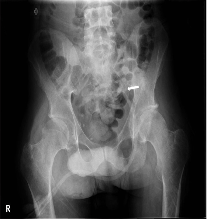
Spinal cord stimulator (SCS) systems (Fig. 1) are being increasingly used for the management of chronic neuropathic and oncological pain, chronic pain from vascular etiology and intractable angina. A SCS system comprises a pulse generator and insulator wire lead(s) that attach to several metallic contact points. Several lead designs exist ranging from paddle type to cylindrical tube leads. The lead(s) are typically positioned in the epidural space under fluoroscopy either through a percutaneous approach or via mini-laminotomy. Depending upon the location of the pain, i.e., upper extremity and chest pain or lower back and lower extremity pain, the leads are optimally placed in the upper thoracic/cervical levels and lower thoracic levels respectively. The number of metallic contact points and the contact spacing depends on the management goal. The impulse generator is implanted subcutaneously either in the back, buttock, or in the abdominal wall. SCS systems used for chronic bilateral neuropathic pain often have dual leads, which ideally should be placed symmetrical to the spinal cord at a 3 mm center to center separation just outside the dura mater, and the lead alignment should be parallel to each other at the exact spinal level. While evaluating these devices on radiographs, the leads should be followed from the impulse generator to the spinal canal to ensure that they are intact. Radiographs are useful for identifying lead fracture and migration (approximately 12%) that can lead to therapeutic failure by comparing with prior radiographs (1).
Figure 1.
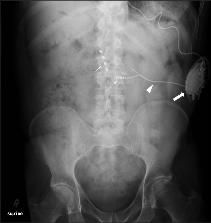
AXR shows a spinal cord stimulator placed for chronic back pain. Note its various parts: the pulse generator (thick arrow), its wire lead (arrowhead) and metallic contact points (thin arrows).
Sacral nerve stimulators provide stimulation to the sacral nerve via a lead placed through the S3 neural foramen. Clinical indications include urinary urge incontinence/frequency, nonobstructive urinary retention, detrusor hyperactivity and fecal incontinence. Like the SCS system, this device too has a pulse generator with a wire lead. The wire lead is attached to a quadripolar electrode (Fig. 2) that is usually inserted under fluoroscopy. Initial test period involves attaching a temporary electrode connected to an external pulse generator. Once the patient demonstrates symptomatic improvement, an implantable pulse generator is used. A recent study showed no correlation between long-term response to sacral nerve stimulation and the electrode position on follow-up x-rays. The most common complication with this device is lead migration (approximately 12%) and can be identified by radiography (2).
Figure 2.
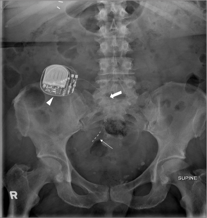
AXR shows a sacral nerve stimulator placed in a patient with a neurogenic bladder. Note its various parts: the pulse generator (arrowhead), its wire lead (thick arrow), and quadripolar electrodes (thin arrow).
Ventriculoperitoneal (VP) shunt
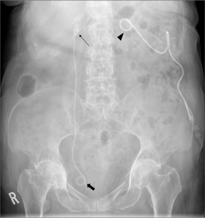
A VP shunt is used for managing hydrocephalus. A basic VP shunt comprises of a proximal catheter, reservoir, valve, and a distal catheter. The proximal catheter is placed in one of the lateral ventricles, and it exits through a burr hole, connected to the reservoir in the subcutaneous tissue. Shunts are commonly placed in the peritoneum (ventriculoperitoneal shunt), right atrium (ventriculoatrial shunt) or pleural space (ventriculopleral shunt). VP shunts by far are the most preferred as they are associated with fewer complications. A standard radiographic series (shunt series) includes a frontal and lateral radiograph of the head and neck and frontal radiographs of the chest and abdomen (Fig. 3) to evaluate the entire shunt. Complications that can be identified on chest radiograph include breaks, disconnections and migrations of the distal catheter, pneumothorax, subcutaneous emphysema, and features of pulmonary hypertension (3).
Figure 3. a–c.

Frontal radiograph (a) of the head and neck of a basic VP shunt series shows the proximal catheter (thick arrow) exiting the right lateral ventricle. Chest radiograph (b) of a basic VP shunt series shows the traversing shunt catheter (arrowheads). Abdominal radiograph (c) of a basic VP shunt series shows the distal catheter (arrow) in the right lower pelvis.
Lumboperitoneal (LP) shunt
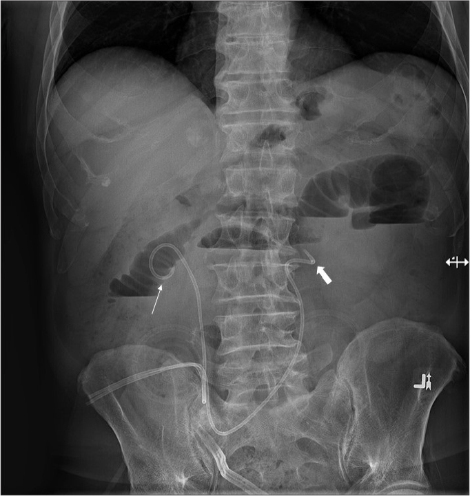
LP shunts in the past were the main treatment for cerebrospinal fluid (CSF) diversion for the management of idiopathic intracranial hypertension (IIH). The main advantage of an LP shunt over a VP shunt is that in the former it is much easier to access the CSF space (thecal sac), while inserting the catheter of a VP shunt would be difficult into the slit ventricles commonly seen in patients with IIH. The conus medullaris is the distal tapered end of the spinal cord and studies have shown that the conus medullaris lies at the L1–L2 level. Due to the proximity of the conus medullaris, an ideal position for LP shunt catheter placement is at or below L3/L4 level (Fig. 4). In order to obtain simultaneous access to the lumbar spine and flank, the LP shunt is generally positioned in the lateral position. On entering the thecal sac the proximal catheter is threaded cranially into position. Inadvertent catheter kinking is a common complication due to the large amount of tissue in this region. Following placement of the proximal catheter, the remainder is tunneled through the subcutaneous tissue into the flank region within the peritoneum. Catheter migration is a recognized complication ranging from 3%–20%, with the lumbar (proximal) catheter usually migrating into the subcutaneous space or the peritoneal portion of the catheter coming out of the peritoneum. Radiographs are useful for assessing catheter migration and kinking (4).
Figure 4.
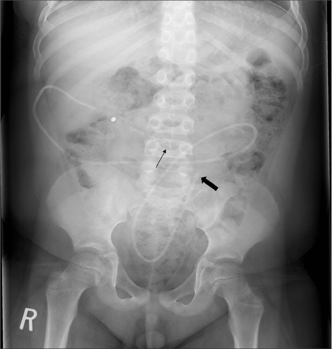
AXR shows a lumboperitoneal (LP) shunt. Note the lumbar catheter (thin arrow) enters the CSF space at L4 level, while the peritoneal catheter (thick arrow) is in the left lower quadrant.
Epidural catheter
An epidural catheter (Fig. 5) is a commonly used medical device placed for administration of anesthesia in managing pain from various causes. The catheter may be radiolucent or radiopaque, with the former allowing visualization of drug administration and blood in the catheter. The radiopaque catheter can be visualized by imaging. One of the documented complications associated with this device is catheter breakage, which can be identified on radiographs. In symptomatic patients, especially those with retained subarachnoid catheter fragments, surgical removal is recommended to avoid neurological complications (5).
Figure 5.
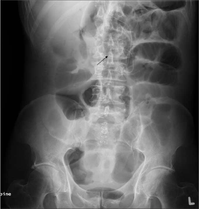
AXR shows an epidural catheter with its tip in the epidural space (arrow).
Intrathecal baclofen (ITB) pump
ITB pump (Fig. 6) is a device used mainly for treating spinal cord related spasticity. The pump continuously delivers the drug (baclofen) to the target site in the spinal cord, improving muscle spasm. The use of ITB pump has extended to other conditions such as cerebral palsy, spinal cord injury, traumatic or hypoxic-anoxic brain injury, multiple sclerosis, and stroke. The device consists of a programmable pump reservoir that is implanted subcutaneously in the anterolateral wall of the abdomen and tunneled silicon catheters extending into the spinal canal intrathecally at the midlumbar level for continuous supply of the drug. Disruption or malfunction of the ITB pump (Fig. 7) can lead to baclofen withdrawal syndrome (e.g., fever, hallucination, rebound spasticity). Plain radiography is the initial imaging modality used for evaluation of the ITB pump when a malfunction is suspected. A standard series for evaluation of an ITB pump includes an AXR, lumbar spine radiographs (AP and lateral) and an AP thoracic spine x-ray. Complications that can be detected on radiography include catheter kinking, migration, discontinuity, and dislodgement (6).
Figure 6. a, b.

AXR (a) shows an IsoMed baclofen pump (arrowhead) with its infusion port (thin arrow) accurately positioned for infusion of the drug (baclofen). AXR (b) of the same patient taken a few years later shows that the IsoMed baclofen pump has been replaced by a programmable SynchroMed pump (thick arrow). Its infusion port is satisfactorily positioned for infusion of the drug (baclofen).
Figure 7.
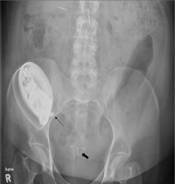
AXR shows a malpositioned baclofen pump that has flipped subcutaneously. Note its infusion port (thin arrow) is oriented medially preventing infusion of the drug. An intrauterine contraceptive device (IUCD) (thick arrow) is noted within the pelvis.
Genitourinary devices
Nephrostomy tubes
Indications for nephrostomy tubes (Fig. 8) include urinary diversion, relieving urinary obstruction, diagnostic testing and access for therapeutic interventions. Percutaneous nephrostomy placement is preferred over surgical. Complications associated with nephrostomy tube placement that may be visualized on radiographs include pneumothorax, hemothorax, pneumoperitoneum, and tube dislodgement (7).
Figure 8.
AXR shows a left nephrostomy tube (arrowhead) and a right double J (DJ) stent with its proximal (thin arrow) and distal (thick arrow) ends accurately reconstituted in the right renal pelvis and bladder respectively.
Ureteric stent
Ureteric stents are an indispensable tool in urology. Indications for ureteric stent placement include relief of obstruction (benign and malignant causes) adjunct to stone therapy, perioperative placement, and management of urine leak secondary to trauma, fistula, or following surgery. Irrespective of the stent material, the devices need to be replaced every 3–6 months. AXRs are useful for evaluating stent placement. An accurately placed stent (Fig. 9) should have its proximal pig tail completely reconstituted within the renal pelvis and its distal loop above the bladder base, to prevent stent migration and reduce incidence of irritative bladder symptoms from impingement of the stent on the bladder base. AXRs are useful for assessing stent migration (upwards or downwards) (Fig. 9), encrustation, and stent fracture. AXRs are also useful for identifying “forgotten” stents left behind over time, which have medicolegal implications (8).
Figure 9.
AXR shows bilateral ureteric stents placed into an ileal conduit. Note that the right ureteric stent (thin arrow) is accurately positioned in the right renal pelvis, while the left ureter stent (thick arrow) has migrated distally into the proximal ureter.
Foley catheter
Nearly 25% of all hospitalized patients undergo bladder catheterization. Foley catheters have self-retaining inflatable balloons. An accurately positioned Foley catheter should have its balloon located within the urinary bladder, but in malpositioned cases such as in the urethra (Fig. 10), the balloon shadow may be seen below the urinary bladder (9). Some Foley catheters have radio-opaque markers enabling its tip to be identified on pelvic radiographs (10), while others have a secondary lumen containing an electrically insulated thermistor that acts as a temperature probe to monitor urine temperature (11). The two most common complications seen after urethral catheterization in males, are urethral trauma and retention of the catheter balloon in the urethra. Another location for catheter malposition that have been documented is in the ureter which can cause hydroureteronephrosis or even ureteral rupture (12).
Figure 10.
Pelvic radiograph shows a urinary bladder catheter (arrow) malpositioned in the urethra.
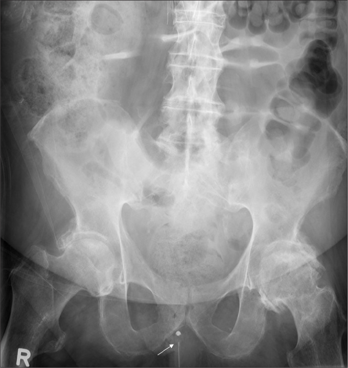
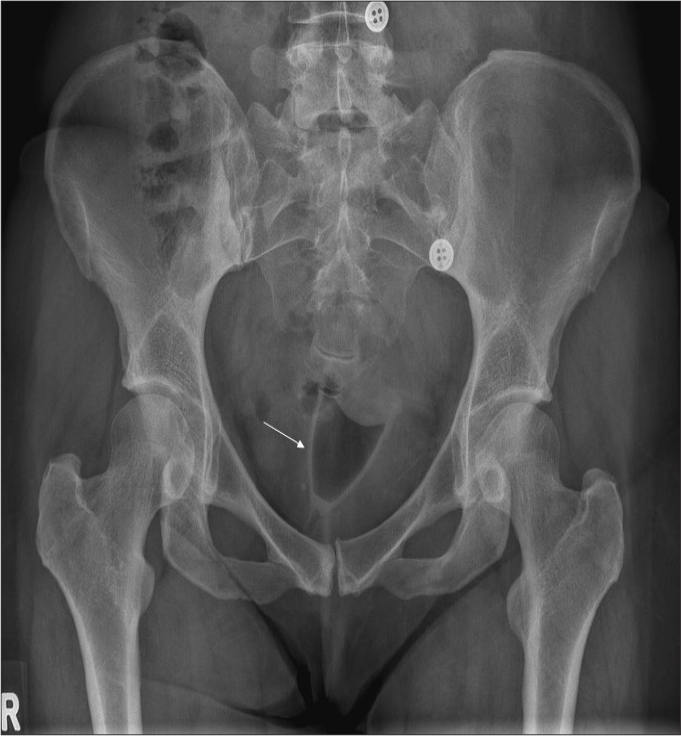
Suprapubic catheterization (Fig. 11) is an alternate procedure to urethral catheterization in patients with conditions such as symptomatic bladder obstruction and neurogenic bladder requiring long-term urinary drainage. Complications that can be identified on radiography include inadvertent catheterization of the urethra (13), retained catheter, and encrustations (14).
Figure 11.
Pelvic radiograph shows a suprapubic catheter (arrow).
Continuous ambulatory peritoneal dialysis (CAPD) catheter
Continuous ambulatory peritoneal dialysis (CAPD) is a common method for managing chronic renal failure. CAPD when compared to hemodialysis offers the advantage of freedom of ambulation to the patient. Other advantages include lesser cardiac stress, fewer dietary restriction and being less expensive. CAPD catheters are available in various designs and include a single or double cuff. The double cuff catheters have a superficial subcutaneous cuff and a deep peritoneal cuff. The most commonly used CAPD catheter is a straight double cuff Tenckhoff catheter. As the dialysate pools dependently during ambulation, in order to ensure proper outflow dialysate exchange, the distal catheter tip must be in the pelvis (i.e., inserted in a dependent position into the rectovesical and rectouterine pouches in males and females, respectively) (Fig. 12a). Nearly 57% of all CAPD catheters migrate within the first year of placement. The biggest limiting factor to CAPD is that it has poor long-term effectiveness because of it being prone to complications. Complications related to CAPD can be classified as infectious and noninfectious. AXRs are useful for evaluating noninfectious complications such catheter malposition/migration (Fig. 12b) and kinking (Fig. 12c) (15).
Figure 12. a–c.

AXR (a) shows a continuous ambulatory peritoneal dialysis (CAPD) catheter with its tip (arrow) accurately positioned in the lower pelvis. AXR (b) shows a CAPD catheter with its tip (arrow) malpositioned in the right lower quadrant. AXR (c) shows a kinked (arrow) CAPD catheter making it nonfunctional.
Intrauterine contraceptive devices (IUCDs)
IUCDs (Fig. 13) are commonly used for birth control. Ultrasound is the most commonly used imaging modality for evaluating IUCDs. However, AXRs have the following roles: 1) to confirm that the IUCD is in the pelvis when it is not identified by ultrasound; 2) old generation IUCDs such as Lippes Loop and Saf-t-coil are straightened prior to inserting, and following insertion, a pelvic radiograph confirms whether the IUCD has retained its original shape, as failure to do so can lead to its failure; 3) to exclude complications such as perforation or migration (Fig. 14) (16); 4) to confirm retained IUCDs with or without encrustations; and 5) to identify/locate IUCD fragments (17).
Figure 13. a–c.

Pelvic radiograph shows a Mirena IUCD. Pelvic radiograph (b) shows a Multiload- 375 IUCD. Pelvic radiograph (c) shows a Lippes loop IUCD.
Figure 14. a, b.

Pelvic radiograph (a) shows an IUCD after initial placement. Pelvic radiograph (b) of the same patient taken 2 years later shows that the IUCD has perforated and migrated and was confirmed on ultrasound to be extrauterine in location.
Tubal sterilization devices
Tubal sterilization is the most commonly used sterilization technique worldwide. Introduced in 1981, the Filshie® clip (Cooper Surgical) is one of the most accepted tubal sterilization devices. Pelvic radiographs are useful for assessing accurate positioning of the devices and for ruling out complications such as device migration (Fig. 15). About 25% of the patients with Filshie clips will eventually develop clip migration. However, only 0.6 per 1000 patients will develop migration related symptoms (18).
Figure 15. a, b.

AXR (a) shows a Filshie clip in the left lower pelvis (arrow). Chest radiograph (b) of the same patient shows that the right Filshie clip (arrow) had migrated to the right upper quadrant and sits just under the right hemidiaphragm.
Since its FDA approval in 2002, the Essure® microinserts (Conceptus, Inc.) have been gaining popularity as an alternative device. Under hysteroscopic guidance, both the tubal ostia are identified and the Essure microinserts are inserted into both proximal fallopian tubes and the devices are deployed. As per the recent manufacturer’s recommendations, a pelvic radiograph should be performed 3 months post device implantation. Correctly positioned Essure microinserts on pelvic radiographs should satisfy the following: 1) horizontal orientation of the bilateral microinserts without angulation and a symmetric appearance; and 2) the distance between the two proximal markers should be normally <4 cm (19).
Menstrual cup
Menstrual cups (Fig. 16) also known as catamenial sacks have been available for decades, but their use is limited due to their bulky design and the need for multiple sizes. The newer menstrual cups are smaller, more flexible and made of silicone or latex rubber. Unlike tampons or pads that absorb the menstrual flow, these cups collect it. Radiologists need to be aware of its appearance on radiographs (20).
Figure 16.
Pelvic radiograph shows a menstrual cup (arrow).
Vaginal pessary
It is a rubber or silicone device placed in the vagina to prevent pelvic organ collapse. An ideally positioned pessary (Fig. 17a) would be in the posterior aspect of the vagina around the cervix. The device is most frequently placed in older women with complaints of pelvic floor laxity. The vaginal ring pessary (Fig. 17b) has a similar appearance to the vaginal contraceptive ring. On radiographs they appear as large thick rimmed rings of uniform high density perpendicular to the plane of the vagina (21). Radiographs can help identify a malpositioned vaginal pessary (Fig. 17c).
Figure 17. a–c.

Pelvic radiograph (a) shows an accurately positioned vaginal Gellhorn pessary (arrow). Pelvic radiograph (b) shows a vaginal ring pessary. Pelvic radiograph (c) shows a malpositioned vaginal Gellhorn pessary (arrow).
Vaginal tampon
A vaginal tampon (Fig. 18) is an incidental finding frequently seen on radiographs of menstruating women. On imaging, the vaginal tampon takes the shape and orientation of the vaginal canal and resembles air in attenuation, because of the gas between the fibers. Occasionally, the string of the tampon may also be seen. Radiologists need to recognize a vaginal tampon, to not get confused with a pathology (21, 22).
Figure 18. a, b.

Pelvic radiograph shows a vaginal tampon (arrow). Sagittal reformatted CT image (b) of the same patient shows the vaginal tampon (thick arrow) and its string (thin arrow).
Penile prostheses (PPs)
The two types of PPs currently available are the malleable or semirigid penile prostheses (MPPs) and the inflatable or hydraulic penile prostheses (IPPs).
The MPPs (Fig. 19a) consists of two paired metallic cylinders/ rods (made of stainless steel/ silver) and coated with silicone or polytetrafluoroethylene that is surgically inserted in both the corpus cavernosum. The advantages with MPPs are that they are inexpensive when compared to IPPs, have lower mechanical failure rate, surgically easier to insert, easy to manipulate (i.e., can be bent upwards when an erection is needed and downwards when not needed), and useful in patients with poor dexterity which would be required for pump manipulation used in IPPs. Major disadvantages with MPPs are that they are prone to lateral perforation and distal erosion and embarrassment or discomfort from permanent erection due to its rigidity.
Figure 19. a–c.

Pelvic radiograph (a) shows the two metallic flexible rods (thin arrows) of a malleable penile prosthesis. Pelvic radiograph (b) shows an inflatable penile prosthesis (IPP). Note that only the metallic rear tip extender (thin arrows) of the IPP is visible on the radiograph. Coronal reformatted CT image (c) of the same patient shows the silicon tubes filled with saline (thick arrows) and the metallic rear tip extender (thin arrow) of the inflatable penile prosthesis.
The IPPs (Fig. 19b, 19c) are of two types: the 3-piece IPP and the 2-piece IPP. The 3-piece IPP consists of two inflatable cylinders (placed in the corpa cavernosa), a pump (placed in the scrotum) and a reservoir (placed adjacent to the urinary bladder), all of which are connected by silicon tubes and filled with saline. Erection is achieved by squeezing the scrotal pump, which pumps saline from the reservoir and in turn inflates the two cylinders by filling up. In a 2-piece IPP, the need for a reservoir is avoided by implanting a resipump (a combination of pump and reservoir) in the scrotum. IPPs have higher patient acceptability by providing the best flaccidity and rigidity close to that of natural erection, and also have better cosmetic results. The disadvantage of this system is a higher mechanical failure rate because of its complex nature; also it is not favored in patients who have had prior pelvic surgeries.
Plain radiographs are useful for evaluating MPPs because of their metallic nature. IPPs were initially filled with radiopaque contrast making them visible on radiographs; however, later on based on manufacture recommendations the contrast was replaced with isotonic saline making them invisible on plain films except for the metallic component of the rear tip extender. PP complications that can be identified on radiographs include prosthetic fracture, migration, and kinking (23).
Prostate brachytherapy seeds
Permanent prostate brachytherapy is the established routine therapy for management of low grade and early stage prostate cancer. It involves ultrasound-guided transperineal insertion of the radioactive “seeds” containing Palladium-103 or Iodine-125, with the latter being the more commonly used isotope due to its lower cost and ease of availability (24). Seed migration (Fig. 20) is a well-known complication seen in approximately 0.7%–55% of the patients, most commonly to the lungs. Other sites of migration that have been documented include the abdomen, pelvis, coronary artery, right ventricle, and left testicular vein. Embolization to the lungs and kidney have led to complications such as radiogenic pneumonitis and renal infarction respectively. Any disparity of the seeds on the initial radiograph with the follow-up images can alert the radiologists about possible seed migration (25).
Figure 20. a, b.

Pelvic radiograph (a) shows prostate brachytherapy seeds. Chest radiograph (b) of the same patient taken 2 years later shows one of the brachy therapy seed has migrated into the left lung (arrow).
Conclusion
Medical devices and materials are frequently being seen on abdominal and pelvic radiographs in everyday practice. It is incumbent for the reporting radiologist to familiarize with these objects not only to evaluate for their accurate placement, but also to look out for complications so that the patient’s physician can be informed promptly and thereby avoid an inadvertent fatality.
Main points.
Abdominal and pelvic radiographs are useful for identifying medical devices, evaluating their accurate placement, and spotting complications following their immediate placement or on follow-up imaging.
Complications that can be evaluated on radiographs related to neurologic devices include device lead wire/catheter malposition, fracture, kinking, and migration.
Complications that can be evaluated on radiographs related to genitourinary devices include malposition, migration, fracture, and kinking.
Acknowledgements
We thank Dr. Tom Ackerman, MD, BSc (med), FRCPC, ABR for contributing images for this project.
Footnotes
Conflict of interest disclosure
The authors declared no conflicts of interest.
References
- 1.Kalia V, Bizzell C, Obray R, Obray J, Lamer T, Carrino JA. Spinal cord stimulation: the types of neurostimulation devices currently being used, and what radiologists need to know when evaluating their appearance on imaging. Curr Probl Diagn Radiol. 2010;39:227–233. doi: 10.1067/j.cpradiol.2009.07.010. [DOI] [PubMed] [Google Scholar]
- 2.Gahzi AA, Banakhar MA, Elterman DS, Hassouna M. Radiographic position of the electrode as a predictor of the outcome of interstim therapy. Int Neurourol J. 2017;21:289–294. doi: 10.5213/inj.1734942.471. [DOI] [PMC free article] [PubMed] [Google Scholar]
- 3.Wallace AN, McConathy J, Menias CO, Bhalla S, Wippold FJ., 2nd Imaging evaluation of CSF shunts. AJR Am J Roentgenol. 2014;202:38–53. doi: 10.2214/AJR.12.10270. [DOI] [PubMed] [Google Scholar]
- 4.Al-Rashed S, Kareem H, Kalra N, D’Antona L, Obeidat M, Patel B, Toma A. Lumboperitoneal shunt insertion without fluoroscopy guidance: Accuracy of placement in a series of 107 procedures. Version 2. F1000Res. 2017;6:565. doi: 10.12688/f1000research.11089.1. [DOI] [PMC free article] [PubMed] [Google Scholar]
- 5.Sbardelotto C, Yoshimi MM, da Pereira RR, de Castro RA. Breakage of a catheter in the epidural space. Rev Bras Anestesiol. 2008;58:643–650. doi: 10.1590/S0034-70942008000600009. [DOI] [PubMed] [Google Scholar]
- 6.Miracle AC, Fox MA, Ayyangar RN, Vyas A, Mukherji SK, Quint DJ. Imaging evaluation of intrathecal baclofen pump-catheter systems. AJNR Am J Neuroradiol. 2011;32:1158–1164. doi: 10.3174/ajnr.A2211. [DOI] [PMC free article] [PubMed] [Google Scholar]
- 7.Dagli M, Ramchandani P. Percutaneous nephrostomy: technical aspects and indications. Semin Intervent Radiol. 2011;28:424–437. doi: 10.1055/s-0031-1296085. [DOI] [PMC free article] [PubMed] [Google Scholar]
- 8.Dyer RB, Chen MY, Zagoria RJ, Regan JD, Hood CG, Kavanagh PV. Complications of ureteral stent placement. Radiographics. 2002;22:1005–1022. doi: 10.1148/radiographics.22.5.g02se081005. [DOI] [PubMed] [Google Scholar]
- 9.Nayeemuddin M, Golash A, George C. Malposition of urinary catheter managed by image-guided intervention. Clin Radiol. 2012;67:1193–1197. doi: 10.1016/j.crad.2012.04.003. [DOI] [PubMed] [Google Scholar]
- 10.Subramanian V, Soni BM, Hughes PL, Singh G, Oo T. The risk of intra-urethral Foley catheter balloon inflation in spinal cord-injured patients: Lessons learned from a retrospective case series. Patient Saf Surg. 2016;10:14. doi: 10.1186/s13037-016-0101-1. [DOI] [PMC free article] [PubMed] [Google Scholar]
- 11.Fallis WM. Monitoring urinary bladder temperature in the intensive care unit: state of the science. Am J Crit Care. 2002;11:38–45. doi: 10.4037/ajcc2002.11.1.38. [DOI] [PubMed] [Google Scholar]
- 12.Luo R, Lee SL, Ng FC, Koh LT. Inadvertent placement of a urinary catheter into the ureter: A report of 3 cases and review of the literature. Asian J Urol. 2017;4:256–261. doi: 10.1016/j.ajur.2016.08.011. [DOI] [PMC free article] [PubMed] [Google Scholar]
- 13.Vaidyanathan S, Hughes PL, Soni BM, Oo T, Singh G. Inadvertent positioning of suprapubic catheter in urethra: a serious complication during change of suprapubic cystostomy in a spina bifida patient - a case report. Cases J. 2009;2:9372. doi: 10.1186/1757-1626-2-9372. [DOI] [PMC free article] [PubMed] [Google Scholar]
- 14.Sharma A, Agarwal S, Sharma D, Veerwal A. Spin-top-like encrustation of suprapubic cystostomy catheter: when proper counselling is all that it takes! BMJ Case Rep. 2018;14:2018. doi: 10.1136/bcr-2018-226726. [DOI] [PMC free article] [PubMed] [Google Scholar]
- 15.Stuart S, Booth TC, Cash CJ, Hameeduddin A, Goode JA, Harvey C, Malhotra A. Complications of continuous ambulatory peritoneal dialysis. Radiographics. 2009;29:441–460. doi: 10.1148/rg.292085136. [DOI] [PubMed] [Google Scholar]
- 16.Mayall EM, Mayall GF. The radiology of the intrauterine contraceptive device. Clin Radiol. 1976;27:541–543. doi: 10.1016/S0009-9260(76)80124-9. [DOI] [PubMed] [Google Scholar]
- 17.Peri N, Graham D, Levine D. Imaging of intrauterine contraceptive devices. J Ultrasound Med. 2007;26:1389–1401. doi: 10.7863/jum.2007.26.10.1389. [DOI] [PubMed] [Google Scholar]
- 18.Renard NY, Jacquemyn Y. Filshie clip migration: A report of two cases. J Obstet Gynaecol. 2012;32:492–493. doi: 10.3109/01443615.2012.669432. [DOI] [PubMed] [Google Scholar]
- 19.Moureau D, Laurent N, Rubod C, Lucot JP, Salleron J, Faye N. Evaluation of tubal microinserts position using 3D ultrasound and pelvic X-ray. Diagn Interv Imaging. 2015;96:1133–1140. doi: 10.1016/j.diii.2014.12.013. [DOI] [PubMed] [Google Scholar]
- 20.Nunes-Carneiro D, Couto T, Cavadas V. Is the menstrual cup harmless? A case report of an unusual cause of renal colic. Int J Surg Case Rep. 2018;46:28–30. doi: 10.1016/j.ijscr.2018.04.002. [DOI] [PMC free article] [PubMed] [Google Scholar]
- 21.Mausner EV, Yitta S, Slywotzky CM, Bennett GL. Commonly encountered foreign bodies and devices in the female pelvis: MDCT appearances. AJR Am J Roentgenol. 2011;196:W461–470. doi: 10.2214/AJR.10.5119. [DOI] [PubMed] [Google Scholar]
- 22.Heffernan EJ, Skehan SJ. Artifact on PET/CT secondary to FDG accumulation in a vaginal tampon. Clin Nucl Med. 2007;32:208–209. doi: 10.1097/01.rlu.0000255018.37567.fd. [DOI] [PubMed] [Google Scholar]
- 23.Ramanathan S, Bertolotto M, Shamsodini A, Heidous MA, Dogra V, Ramchandani P Scrotal and Penile Imaging Working Group of the European Society of Urogenital Radiology. Introduction to imaging of penile prostheses: a primer for the radiologist. AJR Am J Roentgenol. 2018;210:1192–1199. doi: 10.2214/AJR.17.18942. [DOI] [PubMed] [Google Scholar]
- 24.Sachdeva S, Udechukwu NS, Elbelasi H, Landwehr KP, St Clair WH, Winkler MA. Prostate brachytherapy seed migration to the heart seen on cardiovascular computed tomographic angiography. Radiol Case Rep. 2016;12:31–33. doi: 10.1016/j.radcr.2016.10.009. [DOI] [PMC free article] [PubMed] [Google Scholar]
- 25.Maletzki P, Schwab C, Markart P, et al. Late seed migration after prostate brachytherapy with Iod-125 permanent implants. Prostate Int. 2017;6:66–70. doi: 10.1016/j.prnil.2017.09.003. [DOI] [PMC free article] [PubMed] [Google Scholar]