

Abstract

Nanocomposite fibers based on heat-resistant amorphous polyetherimide (PEI) were prepared by twin screw melt micro-extrusion. Vapor-grown carbon nanofibers (VGCFs) and single-wall carbon nanotubes (SWCNTs) were used as fillers which helped to achieve enhanced mechanical properties. The structure and mechanical properties of such nanocomposite fibers were studied. Electron microscopy and melt rheology data revealed a uniform distribution of the nanofillers throughout the volume of the fibers. Wide-angle X-ray scattering showed that the orientational drawing of the nanocomposite fibers led to an improved orientation of the filler particles along the fiber axis. VGCFs or SWCNTs increased the tensile strength and modulus (by ∼275 MPa and ∼5 GPa, respectively) in oriented nanocomposite fibers and decreased deformation at break. SWCNTs were found to be more effective reinforcers than VGCFs.
1. Introduction
Aromatic polyimides show a long-term stability of their mechanical properties under extreme conditions: exposure to high (>200 °C, up to 350 °C) or low (cryogenic) temperatures, gas flows, chemical reagents, and different kinds of radiation. Currently, nearly all of the heat-resistant polymer fibers are prepared by spinning from solutions in high-boiling solvents, the process that is not environmentally friendly and is sometimes technologically problematic. That is why nanocomposite fibers based on thermoplastic aromatic polyimides and produced by melt technology attracted considerable interest. The roles of different structural fragments in the fiber-forming polyimide chains were established and the relationships between the chemical structure, morphological organization, and the properties of polyimide fibers were investigated.1−5
The high heat resistance (temperature of decomposition above 500 °C) and inability to soften only allowed preparing the aromatic polyimide in the form of films and coatings from the melt.1 Thermoplastic linear polyimides, such as the commercially available polyetherimide (PEI) Ultem-1000, with the melting point in a range of 300–320 °C and the melt viscosity of 100–1000 Pa·s at 360–370 °C are easily processed at the temperatures of 360–380 °C. However, this PEI exists only in an amorphous state, and its operating temperature is limited by the glass transition temperature of 220 °C.
In previous studies,5−21 a number of new polyimides and nanocomposite materials containing nanoparticles of various shapes and chemical nature was synthesized and their mechanical characteristics (strength, elastic modulus), thermal, and barrier properties were studied.
To the best of our knowledge, only a few works22−24 on the melt-processed materials have been published, and just in two of them22,23 the results on melt-extruded Ultem-1000 fibers were reported. The fabricated fibers of pure PEI exhibited tensile strengths ranging from 138 to 207 MPa for average draw ratios of 4.5–10.3, while moduli ranged from 2.70 to 3.22 GPa.22 The oriented (up to draw ratio ∼3) nanocomposite PEI fibers filled with single-wall carbon nanotubes (SWCNTs) exhibited a tensile strength of 105 MPa and modulus of 3.1 GPa.23
Carbon nanoparticles, such as nanotubes (CNTs) and nanofibers, increase the strength and elastic properties of polyimides.15,16 Multiwall carbon nanotubes (MWCNTs) increased the value of elastic modulus and yield stress by about 37%, but deformation at the break of the nanocomposite decreased simultaneously.17 MWCNTs (14 wt %) raised the glass transition temperature of the nanocomposite polymer from 335 to 357 °C. The carbon nanotubes could also limit the mobility of the macromolecules by cross-linking.
Chemical modification of the nanofiller surface in a mixture of 98% sulfuric acid and 70% nitric acid (3:1) improved adhesion between the CNTs and the polyimide matrix that affected positively the mechanical properties of the films.19 CNTs (5 wt %) increased the strength of the nanocomposite by 40% compared to the pure polyimide matrix. However, further increase in the CNT concentration decreased the strength, even though it remained above the level typical of the pure polymer.
Introduction of nanoparticles with various chemical structures and shapes in the polyimide matrix even at low concentrations (3–5 wt %) improved the strength and elastic modulus of the nanocomposites and, in some cases, increased their heat resistance.6−17,19,21 Nevertheless, even the modified nanoparticles were unable to improve the whole set of the important polymer mechanical properties simultaneously.
The unique properties of anisodiametric nanoparticles can be used most effectively in fibrous structures. In this work, we prepared polyimide nanocomposite fibers filled with carbon anisodiametric nanoparticles and studied the relationships between their structure and mechanical and thermal properties.
2. Results and Discussion
2.1. Melt Rheology
The structure, spatial distribution, and size of the filler nanoparticles are the key factors which need to be controlled. This requires the use of special equipment (high-resolution X-ray tomography, etc.) that is not always available. Rheological methods are used to assess the degree of dispersion of nanoparticles in polymer melts.25−27 The analysis of the viscosity was made for the fibers melted directly in a rheometer measuring unit. The test was performed in the shear mode. Figure 1 illustrates the rheological behavior of PEI melts filled with SWCNT (Figure 1a) and vapor-grown carbon nanofibers (VGCFs) carbon nanofibers (Figure 1b). SWCNTs (0.5 wt %) and VGCFs (5 wt %) increased the melt viscosity considerably. This is probably due to the formation of a structural network of nanotubes in the polymer matrix.28 With increasing shear rate, the bonds in this network are destroyed, which leads to a decrease in the viscosity. Moreover, such a structural network can be formed because of both a direct interaction between nanoparticles and interaction through the matrix layer.29 The increase in viscosity at low shear rates is most significant with the introduction of SWCNTs (Figure 1a). Owing to the high degree of anisometry (the ratio of length to diameter is ∼1000) and a large specific surface (∼530 m2/g) of nanoparticles, a strong adsorption interaction of polyimide molecules with the surface of the carbon nanotubes occurs. All this leads to the formation of a stronger structural network of SWCNTs compared to that of VGCFs and, therefore, a higher shear force is required for its destruction.
Figure 1.

Dependence of the viscosity of the PEI melt filled with SWCNTs (a) and VGCF nanofibers (b) on the shear rate.
The interaction and structuring in the matrix occur on much smaller scales for VGCFs (the aspect ratio is ∼30–100, and the specific surface area is ∼13 m2/g) than for SWCNTs, and higher concentrations are required for a quantitatively similar effect.
This indicates a fairly good dispersion of both kinds of nanoparticles in the volume of the PEI matrix. However, the concentrations above 0.5 wt % SWCNTs and 5 wt % VGCFs make it difficult to obtain high-quality defect-free fibers because of the high melt viscosity.
2.2. Scanning Electron Microscopy
To control the nanofiller dispersion in the final product, we prepared cryo-cleaved cross sections of the fibers and investigated them with a scanning electron microscope. Figures 2 and 3 show scanning electron microscopy (SEM) micrographs of the PEI fibers filled with SWCNTs and VGCFs, respectively.
Figure 2.
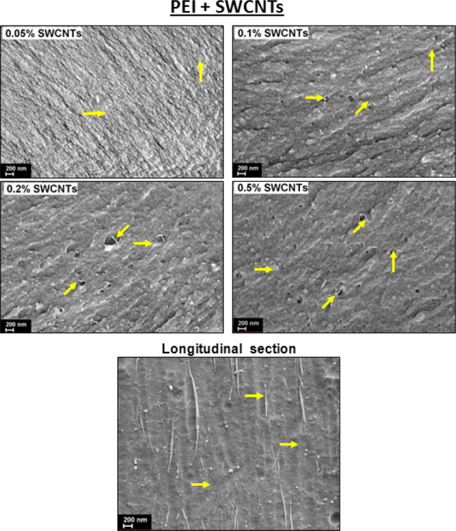
Scanning electron micrographs of the cross sections of the PEI nanocomposite fibers with different percentage of SWCNTs. Some single-wall nanotubes and their agglomerates observed in the fibers are indicated by arrows. The SEM micrograph of longitudinal section of the fiber with 0.5 wt % SWCNTs is presented as well (fiber axis is vertical).
Figure 3.

Scanning electron micrographs of the cross sections of the nanocomposite fibers based on PEI filled with different amounts of VGCFs. Some nanoparticles observed in the fibers are indicated by arrows. SEM micrograph of the longitudinal section of the fiber with 1 wt % VGCFs is presented as well (fiber axis is vertical).
As seen in Figures 2 and 3, both kinds of nanoparticles are well distributed in the polymer matrix inside the nanocomposite fibers. Only a few small aggregates of several particles were found in the fibers with 5 wt % VGCFs. Longitudinal sections of some fibers are presented as well (the longitudinal sections of nanocomposite fibers with other concentrations of SWCNTs and VGCFs were also examined by SEM; no significant differences were found in the images of samples with different concentrations of the same filler; the main differences are only in the number of visible nanoparticles). It is evidently seen that both kinds of nanoparticles are quite well oriented along the extrusion direction even before high-temperature drawing. Further orientational drawing will lead to improvement of nanoparticle orientation.
It is worthy to note that both SWCNTs and VGCFs could be easily pulled out from the PEI matrix during fiber breaking indicating weak adhesion between the nanoparticles and the polymer. Therefore, the “filler-polymer” interface zones can be considered as numerous defects inside the nanocomposite material that could lead to a reduction of some properties of the obtained fibers, especially at high concentrations of nanofillers.
2.3. Wide-Angle X-ray Scattering
Wide-angle X-ray scattering (WAXS) was used to characterize the structure of the fibers. Figure 4 shows 2D-diffraction patterns obtained in transmission mode for the vertically aligned fibers filled with anisometric nanoparticles of SWCNTs and VGCFs. It is seen that the polymer matrix has no crystalline structure: only an amorphous halo is observed with a uniform intensity distribution along the ring. A sharp peak of graphite 002, which is produced by the carbon nanoparticles, is present in all of the patterns, and its intensity has a maximum in the equatorial area. This suggests a dominant orientation of the graphite sheets along the fiber axis.
Figure 4.

2D-diffraction patterns of the nanocomposite fibers before and after orientation drawing.
Figure 5a shows an azimuthal profile (along the ring) of the graphite 002 refection observed in a VGCF-filled fiber; its width (full width at half-maximum, Δφ°) characterizes the orientation distribution on a quantitative scale: the sharper the peak, the smaller the dispersion of orientations, and the sharper the texture. For the fibers filled with the single-wall nanotubes, no graphite peaks were observed because of their low concentration in the matrix. Figure 5b illustrates the effect of drawing on the orientation of the VGCF particles. High-temperature orientational drawing of the nanocomposite fibers results in an improved orientation of the filler particles along the fiber axis; the effect becomes less pronounced with increasing concentration of the filler. This should affect the mechanical properties of the fibers, as will be discussed below.
Figure 5.
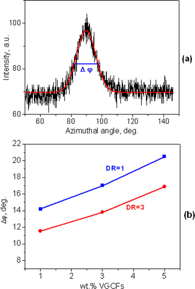
(a) Example of an azimuthal profile of the graphite 002 reflection of VGCFs nanoparticles and (b) dependence of the misorientation degree (Δφ°) of VGCFs on their percentage in the nanocomposite polymer fibers before and after high-temperature orientation drawing.
2.4. Thermal Properties
In Table 1, the decomposition temperatures τ5, τ10, and τ40, at which the sample loses 5, 10, and 40% of its mass [from thermogravimetric analysis (TGA) experiments], respectively, and the glass transition temperatures [from differential scanning calorimetry (DSC) analysis] for all the investigated nanocomposite fibers are listed.
Table 1. Results of Thermal Gravimetrical Analysis (τ5, τ10, τ40, °C) and Differential Scanning Calorimetry (Tg, °C) obtained for all the studied nanocomposite fibers based on PEI.
| temperature
of decomposition, °C |
||||
|---|---|---|---|---|
| fiber | τ5 (5% weight loss) | τ10 (10% weight loss) | τ40 (40% weight loss) | Tg, °C |
| PEI | 522 | 530 | 590 | 217 |
| PEI + 0.05% SWCNTs | 520 | 530 | 630 | 216 |
| PEI + 0.1% SWCNTs | 524 | 531 | 617 | 216 |
| PEI + 0.2% SWCNTs | 524 | 531 | 627 | 217 |
| PEI + 0.5% SWCNTs | 518 | 529 | 604 | 216 |
| PEI + 0.5% VGCFs | 523 | 531 | 597 | 218 |
| PEI + 1% VGCFs | 524 | 529 | 614 | 218 |
| PEI + 3% VGCFs | 525 | 531 | 613 | 217 |
| PEI + 5% VGCFs | 522 | 533 | 644 | 218 |
It is seen that incorporation of neither SWCNTs nor of VGCFs changes the thermal properties (τ5, τ10, and Tg) of the nanocomposite fibers compared to the pure PEI. τ5 and τ10 do not change significantly with the introduction of nanoparticles. However, τ40 rises with increasing nanoparticle content that means changes in the nature of the decomposition of the polymer matrix under the influence of nanoparticles. Similar thermal behavior was found elsewhere.30,31
One can conclude that neither SWCNTs nor VGCFs make all these fibers more stable before their thermal decomposition starts. The same is true for the glass transition temperature, which is nearly the same for pure PEI and for the filled polymer fibers. Introduction of carbon nanofillers of different anisometry degrees does not improve thermal characteristics of the final nanocomposite fibers.
2.5. Mechanical Properties
Carbon nanotubes or nanofibers are well known to be effective modifiers of the mechanical properties of the polymeric material in which they are incorporated.32 To check that SWCNTs and VGCFs would affect the mechanical characteristics of the amorphous PEI fibers, the results of mechanical testing of the nanocomposite fibers are shown in Figure 6.
Figure 6.

Dependencies of strength, deformation at break, and Young’s modulus on the concentration of nanoparticles in unoriented DR = 1 nanocomposite polymer fibers (left plots), and in the fibers exposed to high-temperature orientational drawing DR = 3 (right plots): (a,b) SWCNTs; (c,d) VGCFs.
An increase in the concentration of both SWCNTs and VGCFs in the unoriented (DR = 1) PEI fibers is accompanied by a slight increase in the Young’s modulus and tensile strength as well as by a consistent decrease in deformation at break (Figure 6). A similar effect of carbon nanoparticle incorporation in the polymer matrix was observed in the literature as well.23 VGCF concentration increase from 0 to 5 wt % in the PEI matrix gives rising the Young’s modulus of the fiber by 37% (from 3.0 ± 0.1 to 4.2 ± 0.2 GPa). SWCNTs (0.5 wt %) do not change the Young’s modulus significantly (14% from 3.0 ± 0.1 to 3.3 ± 0.4 GPa). Nevertheless, the changes in the mechanical characteristics (especially—in tensile strength) have similar trends in the nanocomposites of both types. In the curves of strength versus wt % of nanoparticles, the maxima were observed at 0.1 wt % SWCNTs and at 1 wt % VGCFs. With further increase in the concentration of nanoparticles a slowdown in the growth of the Young’s modulus is registered, and even a slight decrease in the tensile strength. The effects are very typical of nanocomposite materials obtained by introducing various nanoparticles into PEIs, for example, montmorillonite, carbon, and hydrosilicate nanotubes.33−35 This indicates the beginning of intensive aggregation of nanoparticles in the bulk of the polymer sample. However, in the PEI fibers the effects of aggregation were not observed up to the maximum concentrations of both VGCFs and SWCNTs. Apparently, a slight decrease in the strength characteristics at 5 wt % VGCFs and 0.5 wt % SWCNTs in the PEI matrix is associated with an elevated level of defects in the matrix because of the weak adhesive interactions between the polymer and nanoparticles.
In the present work, an orientational high-temperature uniaxial drawing was performed up to a maximum degree of DR = 3, which was slightly below the level when the defects and fiber breakage began to appear. As a result of orientational drawing, hardening of the fibers occurred, that was accompanied by an increase in the tensile strength (up to 275 ± 40 MPa) and stiffness (up to 5.03 ± 0.25 GPa) of the investigated fibers, while a drastic reduction in deformations at break (down to 22.7 ± 7%) was simultaneously revealed.
The concentration dependences of the changes in the mechanical properties of the oriented (DR = 3) nanocomposite fibers filled with SWCNTs and VGCFs are also shown in Figure 6. Similarly, the maximum tensile strength was found in the oriented PEI samples having a content of 0.1 wt % SWCNTs and 1 wt % VGCFs. However, it should be noted that in the oriented state, an increase in the carbon nanoparticle concentration did not lead to an intensive decrease in the limiting deformation at break of the studied fibers (Figure 6).
Thus, owing to the cumulative effect of the macromolecule orientation and modification by the carbon nanoparticles, it was possible to increase the tensile strength of the PEI fiber by 2.2 times and the Young’s modulus by 65%.
3. Conclusions
Heat-resistant fibers based on PEI and modified by carbon nanoparticles were obtained using a melt technology. Rotational viscometry and scanning electron microscopy showed that the carbon nanoparticles (SWCNTs and VGCFs) were distributed uniformly and not segregated over the volume of the PEI fibers. WAXS revealed that high-temperature orientational drawing of the nanocomposite fibers resulted in an improved orientation of the filler particles along the fiber axis.
The thermal properties (τ5, τ10, and Tg) were independent of the amount of the nanofillers added, while τ40 increased with adding nanoparticles. This coincides with literature data.30,31
Both SWCNTs and VGCFs produce similar trends in the mechanical characteristics of the filled polymer fibers. A maximum tensile strength was achieved when the concentration of nanofillers reached 0.1 wt % of SWCNTs and 1 wt % of VGCFs in both unoriented nanocomposite fibers and in those after additional high-temperature orientation drawing. It was possible to enhance the tensile strength of the PEI fiber by 2.2 times (up to 275 ± 40 MPa) and the Young’s modulus by 65% (up to 5.03 ± 0.25 GPa). The achieved values of mechanical characteristics are superior to those obtained by other authors22−24 on the melt-processed polyimide fibers. In terms of concentration, SWCNTs were about 10 times more effective reinforcers than VGCFs.
4. Experimental Part
The heat-resistant amorphous PEI Ultem-1000 (SABIC Innovative Plastics, Riyadh, Saudi Arabia) was studied in this work. VGCFs with a diameter of ∼150 nm and length of ∼10–20 μm (Showa Denko, Japan) and SWCNTs with a diameter of ∼1.5 nm and length of ∼1.5 μm (OOO “Carbon ChG”, Russia) were used as fillers with concentrations of 0.5, 1, 3, and 5 wt %, and 0.05, 0.1, 0.2, and 0.5 wt % for VGCFs and SWCNTs, respectively.
Previously, the original PEI pellets were dried in a vacuum oven at a temperature of 150 °C for 5 h. Next, the dried PEI granules were mixed in a dry-sand mold in a ball mill for 10 min with powder of SWCNTs and VGCFs particles at nanoparticle concentrations of 0.05; 0.1; 0.2; 0.5 and 0.5; 1; 3, 5 wt %, respectively. Twin screw microextruder DSM Xplore (Xplore Instruments, Sittard, Netherlands) with a special setup for fiber preparation (DSM Film Device Machine) was used for processing nanocomposite PEI fibers. The dry mixture was loaded into a microextruder heated to 360 °C. The melt was mixed at a temperature of 360 °C for 10 min to disperse the nanoparticle aggregates at a screw rotation speed of 50 rpm. The fiber was formed at a screw rotation speed of 25 rpm at the exit of a microextruder using a round die with a diameter of 1 mm. At the exit from the spinneret, the fiber was cooled by a stream of air and wound at a constant speed onto the receiving coil. The fibers obtained were subjected to an orientation thermal drawing at 230 °C using a homemade setup.
The viscosity of the polymer melt was measured with a rheometer Physica MCR301 (Anton Paar, Graz, Austria) using a cone-plane measuring unit CP25-2 (diameter 25 mm, angle 2°, gap between the cone and plane 0.05 mm) at 360 °C. A fiber sample (150 g) was cut into small pieces and placed in a rheometer measuring unit preheated to 360 °C. The fiber sample, when heated, turned into a viscous flowing state and spread over the surface of the measuring unit of the rheometer. Then, directly for measuring the melt viscosity, a gap between the cone and the plane of the measuring unit of the rheometer was set equal to 0.05 mm. After setting this gap, all possible air bubbles were removed from the sample because of the gradual rotation of the measuring unit. Next, viscosity was measured as a function of shear rate in the range from 1 to 0.01 s–1.
Mechanical tests under tension were carried out using a universal tensile testing machine INSTRON 5943 (Instron, High Wycombe, United Kingdom) using ISO 527 Standard. All fiber diameters were repeatedly measured under an optical microscope. The average diameter of the fibers before orientation drawing was about 300 μm and after drawing 120 μm. The standard deviation did not exceed 10%. The test speed was 10 mm/min. For each type of fiber, 10 samples having the base length of 30 mm were tested. The values of tensile strength, Young’s modulus, and deformation at break were calculated from the stress–strain curves. Strain range for linear fit for Young’s modulus calculation was 0.025–0.25%. The measurement error was not higher than 15%.
Nanoparticle distribution inside the polymer matrix in the nanocomposite fibers was examined by a scanning electron microscope SUPRA-55VP (Carl Zeiss, Munich, Germany) using a secondary electron detector. The fibers were cleaved at the liquid nitrogen temperature. The longitudinal and cross sections were fixed with special glue on the microscope holders and sputtered by a thin layer of platinum. For better visualization of nanoparticles orientation, the longitudinal section was etched by KMnO4 in H3PO4 for 20 min.
The fine crystalline structure of the nanocomposite fibers was investigated by WAXS using a diffractometer D8 DISCOVER (Bruker, Germany) with filtered Cu Kα radiation, point focus, parallel beam, 0.5 mm spot size, and an imagine plate area detector (Anton Paar, Graz, Austria). Azimuthal intensity distribution profiles were registered for the 002 graphite diffraction peaks for the studied polymer nanocomposite fibers before and after drawing.
The thermal properties of the samples were studied by thermal analysis methods with two instruments (NETZSCH, Selb, Germany):
-
1.
TG 209 F1 (TGA)—the tests were carried out in the temperature range 30–800 °C at a heating rate of 10 °C/min, in an argon atmosphere. The weight of samples was 2 mg. As a result of the TGA experiment, the parameters τ5, τ10, and τ40 were determined that correspond to the temperatures, at which the sample loses 5, 10, and 40% of its mass, respectively.
-
2.
DSC 204 F1 (DSC)—the tests were carried out in the temperature range 30–300 °C at a heating rate of 10 °C/min, in an argon atmosphere. The sample weight was 4 mg.
Acknowledgments
The present study has been supported by the Russian Foundation for Basic Research (grant no. 18-03-00963A). The X-Ray diffraction experiments have been performed at the X-ray Diffraction Centre of St. Petersburg State University.
The authors declare no competing financial interest.
References
- Bessonov M. I.; Koton M. M.; Kudryavtsev V. V.; Laius L. A.. Polyimides-Thermally Stable. Polymers; Plenum: New York, 1987; p 328. [Google Scholar]
- Yi M. H.; Huang W.; Jin M. Y.; Choi K.-Y. Synthesis and Characterization of Soluble Polyimides from 1,1-Bis(4-aminophenyl)cyclohexane Derivatives. Macromolecules 1997, 30, 5606–5611. 10.1021/ma9703665. [DOI] [Google Scholar]
- Yudin V. E.; Otaigbe J. U.; Drzal L. T.; Svetlichnyi V. M. Novel semicrystalline thermoplastic R-BAPB type polyimide matrix reinforced by graphite nanoplatelets and carbon nanoparticles. Adv. Compos. Lett. 2006, 15, 137. 10.1177/096369350601500403. [DOI] [Google Scholar]
- Hsiao S.-H.; Liou G.-S.; Chang L.-M. Synthesis and properties of organosoluble polyimide/clay hybrids. J. Appl. Polym. Sci. 2001, 80, 2067–2072. 10.1002/app.1306. [DOI] [Google Scholar]
- Zhang Q.-H.; Dai M.; Ding M.-X.; Chen D.-J.; Gao L.-X. Mechanical properties of BPDA-ODA polyimide fibers. Eur. Polym. J. 2004, 40, 2487–2493. 10.1016/j.eurpolymj.2004.06.020. [DOI] [Google Scholar]
- Kim Y.-J.; Kim J.-H.; Ha S.-W.; Kwon D.; Lee J.-K. Polyimide nanocomposites with functionalized SiO2 nanoparticles: enhanced processability, thermal and mechanical properties. RSC Adv. 2014, 4, 43371–43377. 10.1039/c4ra04952g. [DOI] [Google Scholar]
- Park O.-K.; Hwang J.-Y.; Goh M.; Lee J. H.; Ku B.-C.; You N.-H. Mechanically Strong and Multifunctional Polyimide Nanocomposites Using Amimophenyl Functionalized Graphene Nanosheets. Macromolecules 2013, 46, 3505–3511. 10.1021/ma400185j. [DOI] [Google Scholar]
- Lim J.; Yeo H.; Goh M.; Ku B.-C.; Kim S. G.; Lee H. S.; Park B.; You N.-H. Grafting of Polyimide onto Chemically-Functionalized Graphene Nanosheets for Mechanically-Strong Barrier Membranes. Chem. Mater. 2015, 27, 2040–2047. 10.1021/cm5044254. [DOI] [Google Scholar]
- Liao W.-H.; Yang S.-Y.; Hsiao S.-T.; Wang Y.-S.; Li S.-M.; Ma C.-C. M.; Tien H.-W.; Zeng S.-J. Effect of Octa(aminophenyl) Polyhedral Oligomeric Silsesquioxane Functionalized Graphene Oxide on the Mechanical and Dielectric Properties of Polyimide Composites. ACS Appl. Mater. Interfaces 2014, 6, 15802–15812. 10.1021/am504342j. [DOI] [PubMed] [Google Scholar]
- Yoonessi M.; Shi Y.; Scheiman D. A.; Lebron-Colon M.; Tigelaar D. M.; Weiss R. A.; Meador M. A. Graphene Polyimide Nanocomposites; Thermal, Mechanical, and High-Temperature Shape Memory Effects. ACS Nano 2012, 6, 7644–7655. 10.1021/nn302871y. [DOI] [PubMed] [Google Scholar]
- Zhang L.-B.; Wang J.-Q.; Wang H.-G.; Xu Y.; Wang Z.-F.; Li Z.-P.; Mi Y.-J.; Yang S.-R. Preparation, mechanical and thermal properties of functionalized graphene/polyimide nanocomposites. Composites, Part A 2012, 43, 1537–1545. 10.1016/j.compositesa.2012.03.026. [DOI] [Google Scholar]
- Heo C.; Chang J.-H. Polyimide nanocomposites based on functionalized graphene sheets: Morphologies, thermal properties, and electrical and thermal conductivities. Solid State Sci. 2013, 24, 6–14. 10.1016/j.solidstatesciences.2013.06.012. [DOI] [Google Scholar]
- Park O.-K.; Kim S.-G.; You N.-H.; Ku B.-C.; Hui D.; Lee J. H. Synthesis and properties of iodo functionalized graphene oxide/polyimide nanocomposites. Composites, Part B 2014, 56, 365–371. 10.1016/j.compositesb.2013.08.065. [DOI] [Google Scholar]
- Van Hattum F. W. J.; Benito-Romero J. M.; Madroñero A.; Bernardo C. A. Morphological, mechanical and interfacial analysis of vapour-grown carbon fibres. Carbon 1997, 35, 1175–1183. 10.1016/s0008-6223(97)00111-5. [DOI] [Google Scholar]
- Ounaies Z.; Park C.; Wise K. E.; Siochi E. J.; Harrison J. S. Electrical properties of carbon nanotube reinforced polyimide composites. Compos. Sci. Technol. 2003, 63, 1637–1646. 10.1016/s0266-3538(03)00067-8. [DOI] [Google Scholar]
- Ogasawara T.; Ishida Y.; Ishikawa T.; Yokota R. Characterization of multi-walled carbon nanotube/phenylethynyl terminated polyimide composites. Composites, Part A 2004, 35, 67–74. 10.1016/j.compositesa.2003.09.003. [DOI] [Google Scholar]
- Jiang X.; Bin Y.; Matsuo M. Electrical and mechanical properties of polyimide–carbon nanotubes composites fabricated by in situ polymerization. Polymer 2005, 46, 7418–7424. 10.1016/j.polymer.2005.05.127. [DOI] [Google Scholar]
- Zhu B.; Xie S.; Xu Z.; Xu Y. Preparation and properties of the polyimide/multi-walled carbon nanotubes (MWNTs) nanocomposites. Compos. Sci. Technol. 2006, 66, 548–554. 10.1016/j.compscitech.2005.05.038. [DOI] [Google Scholar]
- So H. H.; Cho J. W.; Sahoo N. G. Effect of carbon nanotubes on mechanical and electrical properties of polyimide/carbon nanotubes nanocomposites. Eur. Polym. J. 2007, 43, 3750–3756. 10.1016/j.eurpolymj.2007.06.025. [DOI] [Google Scholar]
- Yuen S.-M.; Ma C.-C. M.; Lin Y.-Y.; Kuan H.-C. Preparation, morphology and properties of acid and amine modified multiwalled carbon nanotube/polyimide composite. Compos. Sci. Technol. 2007, 67, 2564–2573. 10.1016/j.compscitech.2006.12.006. [DOI] [Google Scholar]
- Yudin V. E.; Svetlichnyi V. M.; Gubanova G. N.; Didenko A. L.; Sukhanova T. E.; Kudryavtsev V. V.; Ratner S.; Marom G. Structure development and interfacial interactions in high-density polyethylene/hydroxyapatite (HDPE/HA) composites molded with preferred orientation. J. Appl. Polym. Sci. 2002, 83, 2873–2882. 10.1002/app.10277. [DOI] [Google Scholar]
- Fay C. C.; Hinkley J. A.; Clair T. L.; Working D. C. Mechanical Properties of LaRCTM-IA and ULTEM® Melt-Extruded Fibers and Melt-Pressed Films. Adv. Perform. Mater. 1998, 5, 193–200. 10.1023/a:1008630431071. [DOI] [Google Scholar]
- Siochi E. J.; Working D. C.; Park C.; Lillehei P. T.; Rouse J. H.; Topping C. C.; Bhattacharyya A. R.; Kumar S. Melt processing of SWCNT-polyimide nanocomposite fibers. Composites, Part B 2004, 35, 439–446. 10.1016/j.compositesb.2003.09.007. [DOI] [Google Scholar]
- Dorsey K. D.; Desai P.; Abhiraman A. S.; Hinkley J. A.; Clair T. L. Structure and properties of melt-extruded laRC-IA (3,4′-ODA 4,4′-ODPA) polyimide fibers. J. Appl. Polym. Sci. 1999, 73, 1215–1222. . [DOI] [Google Scholar]
- Huang Y. Y.; Ahir S. V.; Terentjev E. M. Dispersion rheology of carbon nanotubes in a polymer matrix. Phys. Rev. B 2006, 73, 125422. 10.1103/physrevb.73.125422. [DOI] [PubMed] [Google Scholar]
- Pluart L. L.; Duchet J.; Sautereau H.; Halley P.; Gerard J. F. Rheological properties of organoclay suspensions in epoxy network precursors. Appl. Clay Sci. 2004, 25, 207–219. 10.1016/j.clay.2003.11.004. [DOI] [Google Scholar]
- Vaganov G.; Yudin V.; Vuorinen J.; Molchanov E. Influence of Multiwalled Carbon Nanotubes on the Processing Behavior of Epoxy Powder Compositions and on the Mechanical Properties of their Fiber Reinforced Composites. Polym. Compos. 2016, 37, 2377–2383. 10.1002/pc.23419. [DOI] [Google Scholar]
- Yokozeki T.; Iwahor Y.; Ishiwata S.; Enomoto K. Mechanical properties of CFRP laminates manufactured from unidirectional prepregs using CSCNT-dispersed epoxy. Composites, Part A 2007, 38, 2121–2130. 10.1016/j.compositesa.2007.07.002. [DOI] [Google Scholar]
- Knauert S. T.; Douglas J. F.; Starr F. W. The effect of nanoparticle shape on polymer-nanocomposite rheology and tensile strength. J. Polym. Sci., Part B: Polym. Phys. 2007, 45, 1882–1897. 10.1002/polb.21176. [DOI] [Google Scholar]
- Mo T.-C.; Wang H.-W.; Chen S.-Y.; Yeh Y.-C. Synthesis and characterization of polyimide/multi-walled carbon nanotube. Polym. Compos. 2008, 29, 451–457. 10.1002/pc.20468. [DOI] [Google Scholar]
- Singh B. P.; Singh D.; Mathur R. B.; Dhami T. L. Influence of Surface Modified MWCNTs on the Mechanical, Electrical and Thermal Properties of Polyimide Nanocomposites. Nanoscale Res. Lett. 2008, 3, 444–453. 10.1007/s11671-008-9179-4. [DOI] [Google Scholar]
- Min B. G.; Chae H. G.; Minus M. L.; Kumar S.. Functional Composites of Carbon Nanotubes and Applications; Transworld Research Network: Kerala, India, 2009; pp 43–73. [Google Scholar]
- Yudin V. E.; Otaigbe J. U.; Svetlichnyi V. M.; Korytkova E. N.; Almjasheva O. V.; Gusarov V. V. Effects of nanofiller morphology and aspect ratio on the rheo-mechanical properties of polyimide nanocomposites. Express Polym. Lett. 2008, 2, 485–493. 10.3144/expresspolymlett.2008.58. [DOI] [Google Scholar]
- Gofman I. V.; Svetlichnyi V. M.; Yudin V. E.; Dobrodumov A. V.; Didenko A. L.; Abalov I. V.; Korytkova E. N.; Egorov A. I.; Gusarov V. V. Modification of films of heat-resistant polyimides by adding hydrosilicate and carbon nanoparticles of various geometries. Russ. J. Appl. Chem. 2007, 77, 1158–1163. 10.1134/s1070363207070043. [DOI] [Google Scholar]
- Yudin V. E.; Otaigbe J. U.; Gladchenko S.; Olson B. G.; Nazarenko S.; Korytkova E. N.; Gusarov V. V. New polyimide nanocomposites based on silicate type nanotubes. Dispersion, processing and properties. Polymer 2007, 48, 1306–1315. 10.1016/j.polymer.2007.01.012. [DOI] [Google Scholar]