Abstract
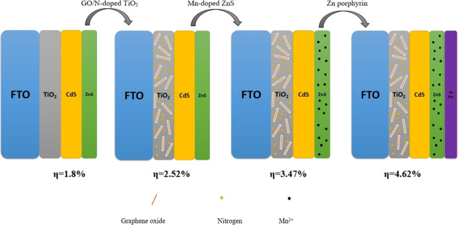
It is vital to acquire power conversion efficiencies comparable to other emerging solar cell technologies by making quantum dot-sensitized solar cells (QDSSCs) competitive. In this study, the effect of graphene oxide (GO), nitrogen, manganese, and a porphyrin compound on the performance of QDSSCs based on a TiO2/CdS/ZnS photoanode was investigated. First, adding GO and nitrogen into TiO2 has a conspicuous impact on the cell efficacy. Both these materials reduce the recombination rate and expand the specific surface area of TiO2 as well as dye loading, reinforcing cell efficiency value. The maximum power conversion efficiency of QDSSC with a GO N-doped photoelectrode was 2.52%. Second, by employing Mn2+ (5 and 10 wt %) doping of ZnS, we have succeeded in considerably improving cell performance (from 2.52 to 3.47%). The reason for this could be for the improvement of the passivation layer of ZnS by Mn2+ ions, bringing about to a smaller recombination of photoinjected electrons with either oxidized dye molecules or electrolyte at the surface of titanium dioxide. However, doping of 15 wt % Mn2+ had an opposite effect and somewhat declined the cell performance. Finally, a Zn-porphyrin dye was added to the CdS/ZnS by a cosensitization method, widening the light absorption range to the NIR (near-infrared region) (>700 nm), leading to the higher short-circuit current density (JSC) and cell efficacy. Utilizing an environmentally safe porphyrin compound into the structure of QDSSC has dramatically enhanced the cell efficacy to 4.62%, which is 40% higher than that of the result obtained from the TiO2/CdS/ZnS photoelectrode without porphyrin coating.
1. Introduction
As one of the momentous renewable energy sources, solar energy could be one of the best candidates for energy supply in the world. For this purpose, innovative ideas are needed to harvest incident solar energy into electrical energy with a higher output to meet the challenging goals for clean energy supply and demand.1,2 Dye-sensitized solar cells (DSSCs) are considered to be an alternative to conventional solid-state solar cells due to the low-cost manufacturing and high photovoltaic performance.3−5 Typically, DSSCs include transparent conducting oxide electrode FTO (fluorine-doped tin oxide), ITO (indium tin oxide) with a TiO2 nanocrystal (as anode), and a counter electrode (as cathode) and an electrolyte containing a redox couple such as iodine/iodide and sulfide/polysulfide.3,4
Quantum dot-sensitized solar cells (QDSSCs) are one of the new generation of solar cells, which are structurally and functionally similar to DSSCs.6−8 Having great properties such as a tunable band gap, high absorption coefficient, and hot electron injection, leading to reduce the dark current and increase the overall efficiency of a solar cell,7 QDSSCs have become a hopeful alternative for DSSCs. So far, research studies have been fulfilled using sensitizing either TiO2 or ZnO nanostructures with low band gap semiconductor quantum dots such as CdS,9 CdSe,10 CdTe,11 PbS,9 InP,12 and PbSe.13
In this study, two ZnS quantum dot layers have been used as passivation layers, reducing the recombination rate of quantum dot CdS solar cells7,14,15 Moreover, doping of transition metal ions such as Mn2+ would influence the optical, electronic, and physical properties of quantum dots. Santra and Kamat have succeeded in significantly improving QDSSC performance by using manganese in the structure. They have found that the doping of CdS/CdSe films with Mn2+ has achieved nearly a 20% enhancement in the power conversion efficiency as compared to undoped films.7
On the other hand, selecting the proper electrolyte and electrocatalyst are the important issue in designing promising QDSSCs with high performance. Using sulfide electrolyte is prevalent instead of iodine electrolyte in QDSSCs. It is confirmed that employing iodine diminishes the conductivity and the surface activity, resulting in reduction in the efficiency.7−9
Additionally, platinum is an ubiquitous material used as an electroctalyst in DSSCs. Regarding the fact that sulfur compounds as an electrolyte are strongly absorbed on the surface of the platinum layer7−9 because of the HSAB theory, this metal is not a good choice for acting as an electrocatalyst in QDSSCs utilizing polysulfide electrolytes. In addition, platinum is an expensive material, which even increases the cost of laboratory-made cells. Considering the shortcomings mentioned above, researchers have been trying to replace new compounds such as hybrid materials,16 carbon materials,17 conductive polymers,18 and inorganic materials instead of platinum. Inorganic materials such as metal sulfides are more noteworthy than the others thanks to their superior electronic conductivity and large specific surface area.19−22 In the present work, we have used a nanostructured CuS film as an electrocatalyst on the counter electrode.
Overall, there are three restrictions in preparing as well as employing QDSSCs, which draw our attention in this study:
-
I.
TiO2 only absorbs lights in the UV light region.
-
II.
High electron recombination rate in the cell.
-
III.
Restrictions on the absorption of light at near-infrared region (NIR) wavelengths.
Although, TiO2 is one of the most commonly used compounds in QDSSC construction as the first layer of the substrate due to its low price and relative thermal stability; nonetheless, it only absorbs light in the visible range mitigating cell efficiency.23 Adding several metals and nonmetals to TiO2 have been examined by researchers for tackling this problem.24−26 Nitrogen is one of the best promising compounds, which has been assayed for this purpose.27−29 According to the reported results, adding nitrogen to TiO2 not only broadens the light absorption range of TiO2 but also increases the amount of dyes (quantum dot dyes) adsorbed on the titanium surface, which in turn enhances both short-circuit current density (JSC) and the efficiency of the cell. Shu and co-workers30 have increased the performance of their designed QDSSC by doping of nitrogen into the TiO2 substrate, thereby increasing the efficiency from 2.14 to 3.67%.
As pointed above, another drawback that can emerge in QDSSCs could be the high electron recombination rate.31−33 In this regard, utilizing ZnS as the passivation layer and the addition of metal ions such as manganese to the quantum dots would significantly decrease the electron recombination rate.34,35 Herein, we have used three strategies simultaneously for achieving the minimum electron recombination rate. In our procedure, in addition to deposition of ZnS as the passivation layer on the top of the layers in the CdS quantum dot and doping of nitrogen and manganese into the ZnS, we have added graphene oxide into the TiO2 substrate with optimum composition percentage.7 Owing to the unique features of graphene oxide, including great thermal stability, wide specific surface area, high flexibility and hardness, high charge carrier mobility (200,000 cm2 V–1 s–1), and high conductivity because of its low band gap, it can be expected that the combination of TiO2 with GO brings about a faster electron transfer and declines the electron recombination rate.36−38
Last but not least, developing organic dyes with a UV–vis–NIR light harvesting capability is one of the best ways to increase light harvesting, which finally rises short-circuit current density (JSC).39,40 It is well-known that a single dye cannot absorb panchromatic sunlight, and it has remained a big problem for the researchers. One solution for dealing with this problem is the modification of photoanodes employing the cosensitization method. According to this procedure, we can use either one or more organic dyes as the second dye (complementary dye), which expands the wavelength range of light absorption from UV–vis to NIR range, resulting in an improvement in the cell efficiency.41−43 Either metal-porphyrin or free-base porphyrin as well as ruthenium complexes is some of the best compounds used in this strategy.44,45 Using environmentally friendly porphyrin compounds render beneficial properties that make these materials suitable for solar cell systems. Simply put, they exhibit high light harvesting ability in the near-infrared region as well as over the whole visible region.
In the current work, we have employed Zn-porphyrin (porphyrin, 5,10-bis(4′-carboxymethylphenyl)-15,20-bis(4′-pyridyl)) into the photoanode of QDSSC and investigated the photovoltaic performance and cell efficiency. To the best of our knowledge, this is the first account of using an environmentally friendly porphyrin compound in the structure of QDSSC based on the TiO2/CdS photoanode. Moreover, it is worth noting that no report has been published concerning the modification of all components of photoelectrodes in one study to enhance the efficiency of QDSSC. So, this shows the importance of our work on this aspect.
2. Experimental Section
2.1. Materials
All the materials used in this study were provided by Sigma-Aldrich and Merck Element and were used as received. Commercial nanocrystalline titania Degussa P25 (specific surface area, 50 m2/g) was used in all cell fabrications. Graphene oxide was synthesized as described in our earlier reports.46 Zinc-porphyrin, namely, 5,10-[bis(4-pyridyl)]-15,20-[bis(4-methylbenzoate)] zinc(II) porphyrin, was synthesized as reported previously.47
2.2. Methods
Scanning electron microscopy (SEM) analysis was used to investigate the surface morphology of compounds on an FTO glass performed by Hitachi (SEM) at 30 kV. Fourier transform infrared spectra were obtained by FTIR 8400S spectrophotometer (Shimadzu, Japan) in the range of 400–4000 cm–1. A diffuse reflectance spectrum (DRS) recorded from a Shimadzu (MPC-2200) spectrophotometer and UV–visible spectrometer (Shimadzu UV-1700) was used in light absorption studies of the synthesized compounds (in the range of 200–800 nm). X-ray diffraction (XRD) analysis was achieved from a JEOL JDX-8030 X-ray powder diffractometer with Cu Kα (l = 0.154 nm) radiation (40 kV, 30 mA). The photocurrent–voltage (J–V) analysis of the cells was measured with a Keithley model 2400 digital source meter (Keithley, USA). IPCE analysis was performed by a device manufactured by our laboratory team with a W Oriel xenon lamp and a Jobin-Yvon monochromator. Electrochemical impedance spectroscopy (EIS) measurements of the cells were achieved under AM 1.5 G simulated light (Luzchem) using potantiostat/galvanostat (PGSTAT 100, Autolab, Eco-Chemie) at an AC amplitude of 10 mV within the frequency range from 0.01 Hz to 500 kHz.
2.3. Preparation of the TiO2 Paste
The TiO2 paste was prepared by stirring (nanocrystalline) nc-TiO2 powders in pure water (30 wt %) with acetylacetone (10 wt %) and polyethylene glycol (PEG) (40 wt % relative to the TiO2) for 1 h.32 We prepared four types of TiO2 pastes by nc-TiO2 powders with different average sizes (15 and 27 nm) and PEG with different molecular weights (20,000 and 500,000). Then, the resulting pastes were cast onto a glass substrate coated with indium-doped tin oxide (ITO) with a Scotch tape as a frame and spacer, raking off the excess solution with a glass rod (squeegee technique). The TiO2 electrodes were dried in air at room temperature for 10 min, annealed at 450 °C for 30 min in a furnace, and then cooled down to rt.
2.4. Fabrication of TiO2/CdS(5)/ZnS(2) Photoelectrode
At first, the TiO2 film was dipped in 0.1 M Cd(NO3)2 solution for 5 min and rinsed with ethanol. Following that, it was dipped for 1 min in 0.1 M Na2S solution. These two steps actually formed a CdS quantum dot layer on the photoelectrode. The number of CdS QDs was increased by repeating the assembly cycles from one to five cycles. For the ZnS passivation layer, the TiO2/CdS film was dipped into 0.1 M Zn(NO3)2 solution for 5 min. Then, it was dipped into 0.1 M Na2S solution for another 5 min. The number of ZnS QDs was increased by repeating the assembly cycles twice. Finally, they were annealed in a vacuum with different temperatures to avoid oxidation.
2.5. Preparation of N-Doped TiO2
N-doped TiO2 particles were prepared using the sol–gel method.48 In this procedure, titanium isopropoxide was dissolved in 100 mL of isopropyl alcohol (IPA) to form a 0.1 M solution and was vigorously stirred at 60 °C for 30 min. Then, hexadecyltrimethylammonium bromide (CTAB) (3.64 g, 0.01 mol) was added to the solution. Following that, PEG 20000 (2 g) was poured to the solution; the resulting mixture was stirred for an additional 30 min and then calcined at 500 °C for 2 h at a ramp rate of 5 °C/min to give a white powder of N-doped TiO2 particles.
2.6. Fabrication of the GO/N-Doped TiO2 Photoelectrode
N-doped TiO2 particles (0.06 g) in each sample were used to prepare GO/N-doped TiO2 pastes. In this regard, 0, 0.001, 0.01, 0.1, and 1 mL of GO was added prior to the first sonication. Then, the prepared pastes were immersed in ethanol and coated on the FTO (fluorine-doped tin oxide) glass using the doctor blade method and subsequently dried at 70 °C for 5 min. Following that, the dried GO/N-doped TiO2 pastes were calcined in an electric furnace at 450 °C for 30 min in air conditions at a heating rate of 5 °C/min. Then, the final electrodes were dipped in a 40 mM TiCl4 solution for 30 min at 70 °C. In the final step, the electrodes were sintered at 450 °C in air at a heating rate of 5 °C/min for 30 min again.
2.7. GO/N-Doped TiO2/CdS(5)/ZnS(2)
GO/N-doped TiO2/CdS(5)/ZnS(2) was prepared by a similar method described in Section 2.4, except that five layers of CdS and two layers of ZnS were deposited on the GO/N-doped TiO2 film.
2.8. GO/N-Doped TiO2/CdS(5)/Mn-Doped ZnS(2)
A similar method to Section 2.4 has been done. However, in the ZnS deposition step, to incorporate doping of Mn2+, manganese acetate (0.025 M) was mixed with zinc nitrate (0.1 M). This allowed coadsorption of Mn2+ and Zn2+ ions, which in turn simplified incorporation of Mn2+ into the ZnS film. Moreover, for comparison purposes, we have prepared three different types of semiconductor photoanodes of 5, 10, and 15 wt % manganese acetate (Mn)-doped ZnS films on GO/N-doped TiO2/CdS(5)/ by the abovementioned SILAR process.
2.9. GO/N-Doped TiO2/CdS(5)/Mn-Doped ZnS(2)/Zn-Porphyrin
To add a porphyrin derivative to the structure of GO/N-doped TiO2/CdS(5)/Mn-doped ZnS(2), the photoelectrode was dipped into a zinc-porphyrin solution (0.5 mM) for 6 h at room temperature and then dried at air conditions.
2.10. Fabrication of a Copper Sulfide (CuS) Counter Electrode7
The CuS counter electrode was prepared using a low-temperature (CBD) chemical bath deposition technique. The ultrasonically well-cleaned, specially holed FTO substrate was vertically immersed in the aqueous solution consisting of 0.1 M copper sulfate pentahydrate, 0.4 M sodium thiosulfate, and 0.7 M acetic acid. Here, copper sulfate acts as the copper source, sodium thiosulfate as the sulfur source, and the acetic acid as the catalyst, which promotes the supply of sulfur for CuS construction. The substrate-dipped growth solution was kept in a hot air oven and maintained at 60 °C. The deposition temperature was maintained for 45 min. Finally, the CuS-coated films were washed several times with DI water, dried and used for preparation of QDSSCs.
2.11. Fabrication of QDSSCs
The structure of QDSSCs was designed using a hot melting sheet (SX 1170-60, Solaronix) at 100 °C, and the internal space was filled with a redox liquid electrolyte containing 1 M Na2S with 2 M S and 0.2 M NaOH in methanol and DI water at a ratio of 7:3.
3. Result and Discussion
3.1. SEM, XRD, IR, and UV–Vis Analysis
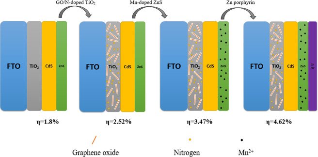
Figure 1 schematically shows the process for preparing our designed photoanode step by step. In our procedure, we have performed three prominent stages for modification of the photoelectrode to achieve higher efficiency cells. These stages include adding GO and nitrogen in the TiO2 substrate, doping of Mn2+ into ZnS passivation layer, and coating of Zn-porphyrin.
Figure 1.
Fabrication process employed to prepare the GO/N-doped TiO2/CdS/Mn-doped ZnS/Zn-porphyrin photoande.
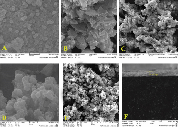
Scanning electron microscopy was applied to study the morphology of TiO2 and CdS nanoparticles as well as the final photoanode containing the porphyrin fragment and Mn doped into ZnS, and Figure 2 shows the top-view SEM images of the samples. As shown (Figure 2A), the TiO2 nanoparticles are deposited almost regularly at the surface of the FTO. Moreover, Figure 2B indicates the graphene oxide sheets incorporated into the titanium dioxide particles. Besides, after adding CdS-ZnS quantum dots to TiO2, the morphological changes of particles are clearly visible (Figure 2C). Finally, Figure 2D,F displays the morphology of the photoanode after doping of manganese and coating of Zn porphyrin, respectively.
Figure 2.
SEM images of (A) TiO2 nanoparticles, (B) GO/N-doped TiO2, (C) GO/N-doped TiO2/CdS/ZnS, (D) GO/N-doped TiO2/CdS/Mn-doped ZnS, (E) GO/N-doped TiO2/CdS/Mn-doped ZnS/Zn-porphyrin, and (F) cross-sectional view of GO/N-doped TiO2/CdS/Mn-doped ZnS/Zn-porphyrin.
Figure 3 shows the XRD patterns of GO N-doped TiO2 and TiO2/CdS/15Mn-doped ZnS. The presence of two peaks at 25 (101) and 48° (200) indicates the anatase phase of the semiconductor compound (TiO2) after deposition on the anode. The XRD peak positions for GO N-doped TiO2/CdS/15Mn-doped ZnS (Figure 3, bottom) are shown at 2θ values of 28.4, 33.2, 47.3, and 56.2° matched with the (111), (200), (220), and (311) ZnS nanoparticles crystalline planes. This accordance confirms the existence of ZnS nanoparticles in the deposited composition.
Figure 3.
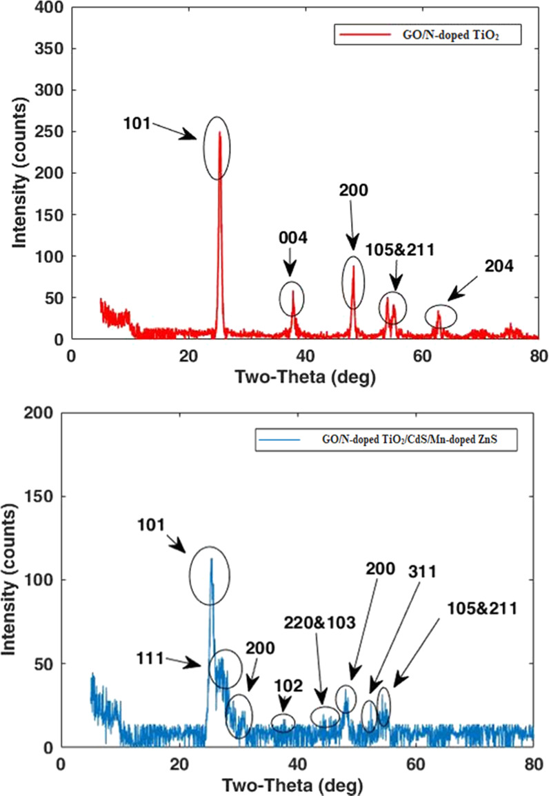
XRD patterns of GO/N-doped TiO2 (top) and TiO2/CdS/Mn-doped ZnS (bottom).
At the same time, the peaks at 28.3, 36.8, and 48.1° exactly correspond to the (101), (102), and (103) planes of CdS nanoparticles. As shown in Figure 3, some XRD peaks have overlapped with each other such as the (102) plane of CdS nanoparticles and the (004) plane of TiO2 nanoparticles. As a final point, the decrease in the peak intensity of TiO2, CdS, and ZnS in GO N-doped TiO2/CdS/15Mn-doped ZnS is mainly due to either the doping of manganese into ZnS or formation of some amorphous substances on the final thin film surface.7 The XRD pattern of the latter film did not differ by adding Zn-porphyrin as well.
FTIR analysis was performed to investigate the bonds and functional groups present in all photoanodes. Based on the obtained data, all photoelectrodes have shown the characteristic bands related to existence of ZnS and CdS in their structures. The FTIR spectrum of the GO/N-doped TiO2/CdS/10Mn-doped ZnS is shown in Figure 4. As depicted in the figure, a broad peak appearing at 3400–3650 cm–1 in the high frequency is ascribed to the stretching mode of O–H bond and reveals the presence of hydroxyl groups in graphene oxide moiety. Moreover, the broad band observed in the region between 1600 and 1730 cm–1 was assigned to the carboxyl group as well as the stretching and bending vibration of OH groups of water molecules adsorbed on graphene oxide.
Figure 4.
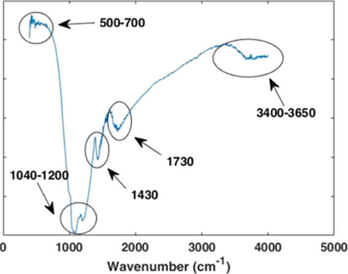
IR spectrum of GO/N-doped TiO2/CdS/10Mn-doped ZnS.
Additionally, the peak at 1430 cm–1 denotes the C–O–C stretching vibration.49 Meanwhile, the observed peaks at 602 and 667 cm–1 are attributed to the Zn–S and Cd–S stretching vibration, respectively.
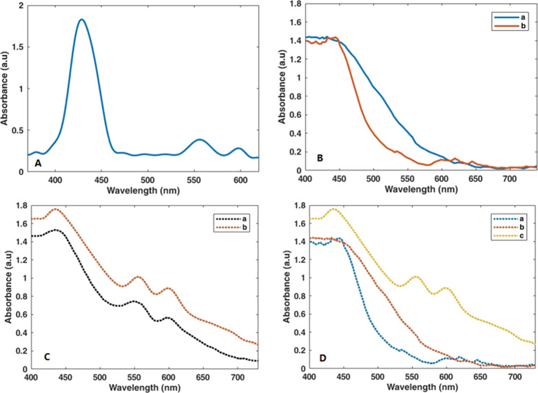
Figure 5 illustrates the UV–vis absorption spectra of porphyrin dye and various photoanodes fabricated in this study. In the UV–vis spectrum of Zn-porphyrin (Figure 5A), an intense Soret band in the 400–460 nm range and moderate Q bands in the 540–610 nm range are observed. According to Figure 5B, after doping of manganese into ZnS, a redshift in the visible region appears.
Figure 5.
UV–vis absorption spectra of (A) Zn-porphyrin dye. (B) a = CdS/ZnS and b = CdS/Mn-doped ZnS (on TiO2). (C) a = CdS/Mn-doped ZnS/Zn-porphyrin (on TiO2) and b = CdS/Mn-doped ZnS/Zn-porphyrin (on GO/N-doped TiO2). (D) a = CdS/ZnS, b = CdS/Mn-doped ZnS, and c = CdS/Mn-doped ZnS/Zn-porphyrin (on GO/N-doped TiO2).
Figure 5C shows the effect of adding nitrogen into the electrode. It can be seen that existing nitrogen brings about a redshift in the spectrum; however, owing to the low amount of nitrogen in the substrate composition, this redshift is moderate. It is well established that the presence of nitrogen not only increases light absorption range but also enhances CdS-ZnS quantum dot adsorption on the surface of TiO2, resulting in the increment of efficiency.48 The most rational explanation for this is that adding nitrogen to the titanium substrate rises the active surface area of the TiO2 from 53.31 to 54.20 m2/g, which in turn results in the increased absorption of corresponding quantum dots onto the substrate. At the same time, graphene oxide sheets can act as a bridge between TiO2 nanoparticles. Here, the presence of graphene oxide sheets among the titanium nanoparticles has caused the expansion of the active surface area of the TiO2 substrate from 54.20 to 57.58 m2/g, which reinforces the effect of existing nitrogen. Figure 5D displays the UV–vis spectrum of the final photoanode after coating of Zn-porphyrin in the structure. Apparently, a broad absorption throughout the 300–750 nm is observed. This large redshift may correspond to the great interaction of porphyrin dye with other components such as GO/N-doped TiO2 and CdS/Mn-doped ZnS in the photoanode structure.
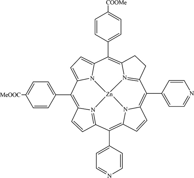
Zn-porphyrin possesses a mesosubstituted structure with two pyridyl groups and two benzoate groups at cis positions to each other (Figure 6). This compound contains functional groups such as a benzoate fragment, which is suitable to act as an anchoring group to TiO2.50 As described earlier, addition of Zn-porphyrin surges the light absorption to 750 nm in the final photoelecrode. Undoubtedly, this major alteration will boost the cell efficacy to a large extent.
Figure 6.
Chemical structure of the Zn-porphyrin employed in the present study.
3.2. J–V and IPCE Analysis
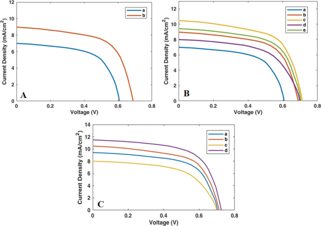
For the purpose of examining the electrical behavior and the energy conversion efficiency of cell construction with the desired compounds, voltage–current (J–V graphs) analysis was accomplished. The electrical properties of all devices prepared in this study are shown in Figure 7. More precisely, data including open-circuit potential (VOC), fill factor (FF), short-circuit current density (JSC), and the efficiency of cell (η) have been listed in Table 1. At first, we have investigated the TiO2/CdS/ZnS electrode and achieved following parameters: VOC = 0.60 V, JSC = 6.98 mA cm–2 FF = 0.46 and η = 1.80%.
Figure 7.
Photocurrent density–voltage graphs of QDSSCs based on several photoanodes: (A) a = TiO2/CdS/ZnS and b = GO/N-doped TiO2 CdS-ZnS. (B) a = CdS/ZnS (on bare TiO2), b = CdS/ZnS (on GO/N-doped TiO2), c = CdS-10Mn-doped ZnS (on GO/N-doped TiO2), d = CdS-15Mn-doped ZnS (on GO/N-doped TiO2), and e = CdS-5Mn-doped ZnS (on GO/N-doped TiO2). (C) a = CdS-5Mn-doped ZnS (on GO/N-doped TiO2), b = CdS-10Mn-doped ZnS (on GO/N-doped TiO2), c = CdS-15Mn-doped ZnS (on GO/N-doped TiO2), and d = CdS-10Mn-doped ZnS/Zn-porphyrin (on GO/N-doped TiO2).
Table 1. Photovoltaic Parameters of QDSSCs Based on Various Photoanodes Fabricated in this Study.
| photoanode | VOC (V) | JSC (mA cm–2) | FF | η % |
|---|---|---|---|---|
| TiO2/CdS/ZnS | 0.60 | 6.98 | 0.46 | 1.80 |
| GO/N-doped TiO2/CdS/ZnS | 0.69 | 8.97 | 0.45 | 2.52 |
| GO/N-doped TiO2/CdS/5MnZnS | 0.70 | 9.42 | 0.50 | 3.07 |
| GO/N-doped TiO2/CdS/10MnZnS | 0.71 | 10.46 | 0.49 | 3.47 |
| GO/N-doped TiO2/CdS/15MnZnS | 0.70 | 7.98 | 0.47 | 2.43 |
| GO/N-doped TiO2/CdS/10MnZnS/Zn-porphyrin | 0.72 | 11.47 | 0.60 | 4.62 |
As can be seen from the aforementioned data, cell efficiency in this case was 1.8%. By adding graphene oxide and nitrogen into the TiO2 segment, the amount of efficacy increased to 2.52%. This enhancement can be justified by the fact that, on the one hand, graphene oxide sheets own high electrical conductivity, resulting in a high charge carrier mobility, and at the same time, existing nitrogen is important as it can produce an extensive surface area on TiO2. Both of these factors can increase the short-circuit current density (JSC) in the cell due to an increase in the rate of electron transfer. Meanwhile, in comparison with a previous study on QDSSCs containing incorporation of graphene oxide and nitrogen into the titanium substrate, which were reported by Kim et al.,48 a noticeable enhancement (44%) in our cell efficacy can be observed. As illustrated before, doping of manganese has been done to improve cell performance. For this purpose, different amounts of manganese (5, 10, and 15 wt %) have been doped into the ZnS passivation layer.
Regarding the J–V graphs, adding 5 and 10 wt % Mn2+ into the ZnS increases cell performance.7,51 However, the latter has a greater effect on the energy conversion efficiency. Yet, employing 15 wt % Mn2+ declines the short-circuit current density (JSC) in the cell and therefore reduces the cell efficiency. The chief cause for the enhancement of cell efficacy (3.07 and 3.47%) in the case of using 5 and 10 wt % manganese is related to the effective diffusion of Mn2+ in the titanium dioxide nanoparticles. However, increasing amount of manganese to 15 wt % has decreased the cell efficiency and JSC as well. That is probably due to the increased recombination rate of charge carriers with electrolyte redox species on the semiconductor interface.7
Finally, according to the results (VOC = 0.72, JSC = 11.47 mA cm–2, FF = 0.60, and η = 4.62%), addition of Zn-porphyrin into the structure of photoelectrode causes a 9.6% increase in the short-circuit current density (from 10.46 to 11.47 mA cm–2), which in turn results in a 33% increase in efficiency (from 3.47 to 4.62%). All of these results indicate a 92% increase in cell efficiency compared to the best results in a similar based quantum dot family conducted by Rao et al.7
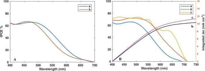
To complete the results of the light absorption analysis by the compounds deposited on the anode, the incident photon-to-carrier conversion efficiency (IPCE) analysis of all the deposited compounds was performed. IPCE analysis was first carried out on the quantum dots of CdS/ZnS and CdS/Mn-doped ZnS deposited on bare TiO2 shown in Figure 8. Both QDSSCs based on doped and undoped manganese into the photoanode exhibit broad response with a maximum IPCE around 65%. In addition, the longer wavelength response of Mn-doped ZnS parallels the behavior seen in the absorption spectra.
Figure 8.
IPCE spectra of QDSSCs based on different photoanodes. (A) a = CdS/ZnS and b = CdS/Mn-doped ZnS. (B) a = CdS/Mn-doped ZnS (on bare TiO2), b = CdS/Mn-doped ZnS (on GO/N-doped TiO2), and c = CdS/Mn-doped ZnS/Zn-porphyrin (on GO/N-doped TiO2). The right-hand axis indicates the integrated photocurrent that is expected to be generated under AM 1.5 G irradiation.
In the following, to evaluate the effect of adding nitrogen to the substrate composition, IPCE analysis was performed on two cells made of bare TiO2 and a GO N-doped TiO2 substrate. As mentioned earlier, addition of nitrogen increases the adsorption of dyes (quantum dots) on the surface of TiO2, therewith increasing the IPCE and efficiency of the cell. In this case, the IPCE percentage has increased from about 65 to 70%. Moreover, coating of porphyrin into the CdS/Mn-doped ZnS has produced a striking change. This system exhibits broad response with a maximum IPCE near 75%. Also, extended wavelength response of the final device in the presence of porphyrin is accordance with the findings of UV–vis spectra.
Additionally, the integrated JSC values for the devices without and with porphyrin coating have been calculated to be 10.37 and 15.68 mA cm–2 (Figure 8B), respectively, which are close to the measured JSC of 10.46 and 15.80 mA cm–2 for corresponding devices. This acknowledges that any mismatch between the simulated sunlight and the AM 1.5 G standard is small.52
3.3. Impedance Analysis and Stability Test
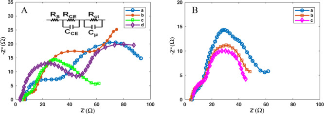
The electrochemical parameters such as the series resistance (RS), the charge transfer resistance at the counter electrode/electrolyte interface (RCE), the charge transfer resistance at the photoanode/electrolyte interface (Rct), and chemical capacitance (Cμ) were obtained directly by the impedance spectroscopy using the ZView software and have been shown in Table 2. Figure 9 shows the Nyquist plots for all devices generated in this work. The inset in the figure contains the equivalent circuit used to fit the plots. As can be seen in Table 2, the RS values decreased gradually from 12.60 to 8.98 Ω in the final cell. The low RS values are beneficial and provide great bonding strength between the photoanode and the FTO substrate, which in turn enhances the collection of more electrons from the external circuit.
Table 2. Fitting Results of the Electrochemical Impedance Spectra of QDSSCs with Different Photoanodes.
| photoanode | RS (Ω) | Rct (Ω) | RCE (Ω) | Cμ (μF) |
|---|---|---|---|---|
| TiO2/CdS/ZnS | 12.60 | 22.08 | 32.30 | 4.98 |
| TiO2/CdS/5MnZnS | 11.19 | 7.06 | 22.12 | 7.43 |
| TiO2/CdS/10MnZnS | 10.03 | 6.30 | 20.30 | 8.83 |
| TiO2/CdS/15MnZnS | 9.21 | 35.13 | 27.60 | 4.79 |
| GO/N-doped TiO2/CdS/10MnZnS | 9.75 | 5.90 | 18.70 | 9.32 |
| GO/N-doped TiO2-CdS-10MnZnS-Zn-porphyrin | 8.98 | 5.30 | 18.10 | 9.96 |
Figure 9.
Nyquist diagrams of QDSSCs fabricated with various photoanodes. (A) a = TiO2/CdS/ZnS, b = TiO2/CdS/5MnZnS, c = TiO2/CdS/10MnZnS, and d = TiO2/CdS/15MnZnS. (B) = a TiO2/CdS/10MnZnS, b = GO/N-doped TiO2/CdS/10MnZnS, and c = GO/N-doped TiO2-CdS-10MnZnS-Zn-porphyrin.
The Rct value of the device containing 10 wt % Mn is 6.30 Ω, indicating the superior charge transfer and electrocatalytic performance at the photoanode/electrolyte interface. However, this figure for the device containing 15 wt % Mn is 35.13 Ω, showing that a higher amount of manganese reduces the electron transfer rate and causes poor efficiency. Moreover, the RCE value of the final cell possessing porphyrin and 10 wt % Mn is 18.10 Ω, which is much lower than the value of an undoped manganese film (32.20 Ω). Increment of this value demonstrates poor catalytic ability; therefore, a decrease in efficiency is observed. Regarding the Cμ value, it gently rises (except in 15 wt % Mn-ZnS) and reaches 9.96 in the final cell possessing porphyrin. The higher Cμ value corresponds to the higher surface area, bringing about better catalytic performance.53
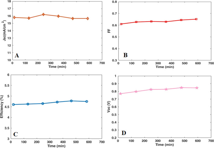
Finally, the stability of the final device based on the GO/N-doped TiO2/CdS/10MnZnS/Zn-porphyrin photoanode was investigated under continuous illumination, which is vital for commercialization. Thus, the long-term stability of the device over 600 min was examined and Figure 10 shows the extracted photovoltaic parameters (η, JSC, FF, and VOC). These parameters exhibited nearly constant with slight fluctuations during the stability test. According to these graphs, the voltage parameter was partially increased until 500 min and then stabilized. These findings revealed the promising stability of our final device during the time mentioned.
Figure 10.
Stability evaluation of J–V curves, (A) JSC, (B) FF, (C) efficiency (%), and (D) VOC for the QDSSC based on the GO/N-doped TiO2-CdS-10MnZnS-Zn-porphyrin photoanode.
4. Conclusions
In summary, several types of QDSSCs based on CdS/TiO2 have been fabricated and fully characterized. Then, on the grounds that some limitations exist in QDSSCs, we have made changes step by step to diminish the relevant restrictions in our designed cells. The most pivotal modification fulfilled in the device includes adding GO into TiO2, doping of nitrogen into TiO2, doping of manganese with different weight percentages into ZnS, and coating of Zn-porphyrin into the photoanode. Not only did adding graphene oxide and nitrogen into TiO2 decrease the rate of electron recombination in the cell and increase the amount of light absorption on the TiO2 surface, but it also expanded the quantum dot CdS/ZnS adsorption on the TiO2 surface. To minimize the electron recombination rate and increase the short-circuit current density (JSC) in the cell, we have doped an optimum amount of Mn (10 wt %) into the ZnS quantum dot as a passivation layer. After making these two important changes in the target cell, we have witnessed a great change in cell efficacy from 1.80 to 3.47%. Moreover, in the final step, we have employed Zn-porphyrin with the cosensitization method in the structure of photoanode. It was found that adding Zn-porphyrin to the quantum dots of CdS/ZnS had a tremendous impact on the cell efficacy. In this case, the efficacy reached 4.62%. This figure is much higher than those reported for TiO2/CdS QDSSCs. Meanwhile, impedance analysis resulted in the lowest electrical resistances Rct and RCE for the final device containing porphyrin and 10 wt % Mn among all devices prepared in this work. This confirms that the appropriate amount of manganese ions alongside with porphyrin was found very effective to improve the surface and electronic properties both in chemical stability and photovoltaic performance.
Acknowledgments
The authors are grateful to Department of Chemistry, Iran University of Science and Technology (IUST), Tehran, Iran, for providing the facilities necessary for the execution of this work.
The authors declare no competing financial interest.
References
- Bing J. M.New Energy Options Inc, assignee. Method and system for predicting solar energy production. U. S. Pat DE 7580817, 2009.
- Hess D. J. Industrial fields and countervailing power: The transformation of distributed solar energy in the United States. Global Environ. Change 2013, 23, 847–855. 10.1016/j.gloenvcha.2013.01.002. [DOI] [Google Scholar]
- Rajavelu K.; Rajakumar P. Synthesis and DSSC application of donor-acceptor stilbenoid dendrimers with triphenylamine as core and benzothiazole as surface unit. Org. Electron. 2018, 56, 192–200. 10.1016/j.orgel.2018.02.020. [DOI] [Google Scholar]
- Sahito I. A.; Sun K. C.; Lee W.; Kim J. P.; Jeong S. H. Graphene nanosheets as counter electrode with phenoxazine dye for efficient dye sensitized solar cell. Org. Electron. 2017, 44, 32–41. 10.1016/j.orgel.2017.01.035. [DOI] [Google Scholar]
- Dhar A.; Kumar N. S.; Paul P. K.; Roy S.; Vekariya R. L. Influence of tagging thiophene bridge unit on optical and electrochemical properties of coumarin based dyes for DSSCs with theoretical insight. Org. Electron. 2018, 53, 280–286. 10.1016/j.orgel.2017.12.007. [DOI] [Google Scholar]
- Shen G.; Du Z.; Pan Z.; Du J.; Zhong X. Solar paint from TiO2 particles supported quantum dots for photoanodes in quantum dot–sensitized solar cells. ACS omega. 2018, 3, 1102–1109. 10.1021/acsomega.7b01761. [DOI] [PMC free article] [PubMed] [Google Scholar]
- Rao S. S.; Durga I. K.; Tulasi-Varma C. V.; Punnoose D.; Kim S.-K.; Kim H.-J. Enhance the performance of quantum dot-sensitized solar cell by manganese-doped ZnS films as a passivation layer. Org. Electron. 2015, 26, 200–207. 10.1016/j.orgel.2015.07.048. [DOI] [Google Scholar]
- Mandal S.; Garcia Iglesias M.; Ince M.; Torres T.; Tkachenko N. V. Photoinduced Energy Transfer in ZnCdSeS Quantum Dot–Phthalocyanines Hybrids. ACS omega. 2018, 3, 10048–10057. 10.1021/acsomega.8b01623. [DOI] [PMC free article] [PubMed] [Google Scholar]
- Pawar S. A.; Patil D. S.; Lokhande A. C.; Gang M. G.; Shin J. C.; Patil P. S.; Kim J. H. Chemical synthesis of CdS onto TiO2 nanorods for quantum dot sensitized solar cells. Opt. Mater. 2016, 58, 46–50. 10.1016/j.optmat.2016.05.019. [DOI] [Google Scholar]
- Firoozi N.; Dehghani H.; Afrooz M.; Khalili S. S. Improvement photovoltaic performance of quantum dot-sensitized solar cells using deposition of metal-doped ZnS passivation layer on the TiO2 photoanode. Microelectron. Eng. 2018, 198, 8–14. 10.1016/j.mee.2018.06.007. [DOI] [Google Scholar]
- Yue G.; Wu J.; Xiao Y.; Lin J.; Huang M.; Lan Z.; Fan L. CdTe quantum dots-sensitized solar cells featuring PCBM/P3HT as hole transport material and assistant sensitizer provide 3.40% efficiency. Electrochim. Acta 2012, 85, 182–186. 10.1016/j.electacta.2012.08.117. [DOI] [Google Scholar]
- Zaban A.; Mićić O. I.; Gregg B. A.; Nozik A. J. Photosensitization of nanoporous TiO2 electrodes with InP quantum dots. Langmuir 1998, 14, 3153–3156. 10.1021/la9713863. [DOI] [Google Scholar]
- King L. A.; Parkinson B. A. Photosensitization of ZnO crystals with iodide-capped PbSe quantum dots. J. Phys. Chem. Lett. 2016, 7, 2844–2848. 10.1021/acs.jpclett.6b01133. [DOI] [PubMed] [Google Scholar]
- Pawar S. A.; Patil D. S.; Jung H. R.; Park J. Y.; Mali S. S.; Hong C. K.; Shin J. C.; Patil P. S.; Kim J. H. Quantum dot sensitized solar cell based on TiO2/CdS/CdSe/ZnS heterostructure. Electrochim. Acta. 2016, 203, 74–83. 10.1016/j.electacta.2016.04.029. [DOI] [Google Scholar]
- Li Z. X.; Xie Y. L.; Xu H.; Wang T. M.; Xu Z. G.; Zhang H. L. Expanding the photoresponse range of TiO2 nanotube arrays by CdS/CdSe/ZnS quantum dots co-modification. J. Photochem. Photobiol. A. Chem. 2011, 224, 25–30. 10.1016/j.jphotochem.2011.09.002. [DOI] [Google Scholar]
- Van Pham C.; Madsuha A. F.; Nguyen T. V.; Krueger M. Graphene-quantum dot hybrid materials on the road to optoelectronic applications. Synth. Met. 2016, 219, 33–43. 10.1016/j.synthmet.2016.04.029. [DOI] [Google Scholar]
- Khalili S. S.; Dehghani H.; Afrooz M. Composite films of metal doped CoS/carbon allotropes; efficient electrocatalyst counter electrodes for high performance quantum dot-sensitized solar cells. J. Colloid Interface Sci. 2017, 493, 32–41. 10.1016/j.jcis.2017.01.005. [DOI] [PubMed] [Google Scholar]
- Yeh M.-H.; Lee C.-P.; Chou C.-Y.; Lin L.-Y.; Wei H.-Y.; Chu C.-W.; Vittal R.; Ho K.-C. Conducting polymer-based counter electrode for a quantum-dot-sensitized solar cell (QDSSC) with a polysulfide electrolyte. Electrochim. Acta 2011, 57, 277–284. 10.1016/j.electacta.2011.03.097. [DOI] [Google Scholar]
- Lee Y.-L.; Lo Y.-S. Highly efficient quantum-dot-sensitized solar cell based on co-sensitization of CdS/CdSe. Adv. Funct. Mater. 2009, 19, 604–609. 10.1002/adfm.200800940. [DOI] [Google Scholar]
- Yang Z.; Chen C.-Y.; Liu C.-W.; Li C.-L.; Chang H.-T. Quantum dot–sensitized solar cells featuring CuS/CoS electrodes provide 4.1% efficiency. Adv. Energy Mater. 2011, 1, 259–264. 10.1002/aenm.201000029. [DOI] [Google Scholar]
- Chen H.; Zhu L.; Liu H.; Li W. Efficient iron sulfide counter electrode for quantum dots-sensitized solar cells. J. Power Sources 2014, 245, 406–410. 10.1016/j.jpowsour.2013.06.004. [DOI] [Google Scholar]
- Balis N.; Dracopoulos V.; Bourikas K.; Lianos P. Quantum dot sensitized solar cells based on an optimized combination of ZnS, CdS and CdSe with CoS and CuS counter electrodes. Electrochim. Acta 2013, 91, 246–252. 10.1016/j.electacta.2013.01.004. [DOI] [Google Scholar]
- Sudhagar P.; Jung J. H.; Park S.; Lee Y. G.; Sathyamoorthy R.; Kang Y. S.; Ahn H. The performance of coupled (CdS: CdSe) quantum dot-sensitized TiO2 nanofibrous solar cells. Electrochem. Commun. 2009, 11, 2220–2224. 10.1016/j.elecom.2009.09.035. [DOI] [Google Scholar]
- Park J.-Y.; Lee K.-H.; Kim B.-S.; Kim C.-S.; Lee S.-E.; Okuyama K.; Jang H.-D.; Kim T.-O. Enhancement of dye-sensitized solar cells using Zr/N-doped TiO2 composites as photoelectrodes. RSC Adv. 2014, 4, 9946–9952. 10.1039/c4ra00194j. [DOI] [Google Scholar]
- Habibi M. H.; Karimi B.; Zendehdel M.; Habibi M. Fabrication, characterization of two nano-composite CuO–ZnO working electrodes for dye-sensitized solar cell. Spectrochim. Acta, Part A. 2013, 116, 374–380. 10.1016/j.saa.2013.07.046. [DOI] [PubMed] [Google Scholar]
- Zhang X.; Liu F.; Huang Q. L.; Zhou G.; Wang Z. S. Dye-sensitized W-doped TiO2 solar cells with a tunable conduction band and suppressed charge recombination. J. Phys. Chem. C 2011, 115, 12665–12671. 10.1021/jp201853c. [DOI] [Google Scholar]
- Lai Y. K.; Huang J. Y.; Zhang H. F.; Subramaniam V. P.; Tang Y. X.; Gong D. G.; Sundar L.; Sun L.; Chen Z.; Lin C. J. Nitrogen-doped TiO2nanotube array films with enhanced photocatalytic activity under various light sources. J. Hazard. Mater. 2010, 184, 855–863. 10.1016/j.jhazmat.2010.08.121. [DOI] [PubMed] [Google Scholar]
- de Souza Filho E. A.; Pieretti E. F.; Bento R. T.; Pillis M. F. Effect of nitrogen-doping on the surface chemistry and corrosion stability of TiO2 films. J. Mater. Res. Technol. 2020, 9, 922–934. 10.1016/j.jmrt.2019.11.032. [DOI] [Google Scholar]
- Park J.-Y.; Lee K.-H.; Kim B.-S.; Kim C.-S.; Lee S.-E.; Okuyama K.; Jang H.-D.; Kim T.-O. Enhancement of dye-sensitized solar cells using Zr/N-doped TiO2 composites as photoelectrodes. RSC Adv. 2014, 4, 9946–9952. 10.1039/c4ra00194j. [DOI] [Google Scholar]
- Shu T.; Xiang P.; Zhou Z. M.; Wang H.; Liu G. H.; Han H. W.; Zhao Y. D. Mesoscopic nitrogen-doped TiO2 spheres for quantum dot-sensitized solar cells. Electrochim. Acta 2012, 68, 166–171. 10.1016/j.electacta.2012.02.068. [DOI] [Google Scholar]
- Subalakshmi K.; Senthilselvan J. Effect of fluorine-doped TiO2 photoanode on electron transport, recombination dynamics and improved DSSC efficiency. Solar Energy. 2018, 171, 914–928. 10.1016/j.solener.2018.06.077. [DOI] [Google Scholar]
- Sharif N. F. M.; Kadir M. Z. A. A.; Shafie S.; Rashid S. A.; Hasan W. Z. W.; Shaban S. Charge transport and electron recombination suppression in dye-sensitized solar cells using graphene quantum dots. Results Phys. 2019, 13, 102171. 10.1016/j.rinp.2019.102171. [DOI] [Google Scholar]
- Aslam M. M.; Ali S. M.; Fatehmulla A.; Farooq W. A.; Atif M.; Al-Dhafiri A. M.; Shar M. A. Growth and characterization of layer by layer CdS–ZnS QDs on dandelion like TiO2 microspheres for QDSSC application. Mater. Sci. Semicond. Process. 2015, 36, 57–64. 10.1016/j.mssp.2015.03.030. [DOI] [Google Scholar]
- Firoozi N.; Dehghani H.; Afrooz M.; Khalili S. S. Improvement photovoltaic performance of quantum dot-sensitized solar cells using deposition of metal-doped ZnS passivation layer on the TiO2 photoanode. Microelectron. Eng. 2018, 198, 8–14. 10.1016/j.mee.2018.06.007. [DOI] [Google Scholar]
- Wang X.; Zhi L.; Müllen K. Transparent, conductive graphene electrodes for dye-sensitized solar cells. Nano Lett. 2008, 8, 323–327. 10.1021/nl072838r. [DOI] [PubMed] [Google Scholar]
- Bostwick A.; McChesney J.; Ohta T.; Rotenberg E.; Seyller T.; Horn K. Experimental studies of the electronic structure of graphene. Prog. Surf. Sci. 2009, 84, 380–413. 10.1016/j.progsurf.2009.08.002. [DOI] [Google Scholar]
- Surana K.; Konwar S.; Singh P. K.; Bhattacharya B. Utilizing reduced graphene oxide for achieving better efficient dye sensitized solar cells. J. Alloys Compd. 2019, 788, 672–676. 10.1016/j.jallcom.2019.02.287. [DOI] [Google Scholar]
- Saji V. S.; Pyo M. Effect of coadsorbents on DSSC sensitized by NIR absorbing poly (ethyl thieno [3, 4-b] thiophene-2-carboxylate). Curr. Appl. Phys. 2010, 10, S410–S413. 10.1016/j.cap.2010.02.011. [DOI] [Google Scholar]
- Tadge P.; Yadav R. S.; Vishwakarma P. K.; Rai S. B.; Chen T. M.; Sapra S.; Ray S. Enhanced photovoltaic performance of Y2O3: Ho3+/Yb3+ upconversion nanophosphor based DSSC and investigation of color tunability in Ho3+/Tm3+/Yb3+ tridoped Y2O3. J. Alloys Compd. 2020, 821, 153230. 10.1016/j.jallcom.2019.153230. [DOI] [Google Scholar]
- Liu D.; Liu J.; Liu J.; Liu S.; Wang C.; Ge Z.; Hao X.; Du N.; Xiao H. The photovoltaic performance of CdS/CdSe quantum dots co-sensitized solar cells based on zinc titanium mixed metal oxides. Phys. E (Amsterdam, Neth.). 2020, 115, 113669. 10.1016/j.physe.2019.113669. [DOI] [Google Scholar]
- Naik P.; Abdellah I. M.; Abdel-Shakour M.; Su R.; Keremane K. S.; El-Shafei A.; Adhikari A. V. Improvement in performance of N3 sensitized DSSCs with structurally simple aniline based organic co-sensitizers. Solar Energy 2018, 174, 999–1007. 10.1016/j.solener.2018.09.071. [DOI] [Google Scholar]
- Naik P.; Su R.; El-Shafei A.; Adhikari A. V. Improved photovoltaic performances of Ru (II) complex sensitized DSSCs by co-sensitization of carbazole based chromophores. Inorg. Chem. Commun. 2017, 86, 241–245. 10.1016/j.inoche.2017.10.030. [DOI] [Google Scholar]
- Jie J.; Xu Q.; Yang G.; Feng Y.; Zhang B. Porphyrin sensitizers involving a fluorine-substituted benzothiadiazole as auxiliary acceptor and thiophene as π bridge for use in dye-sensitized solar cells (DSSCs). Dyes Pigm. 2020, 174, 107984. 10.1016/j.dyepig.2019.107984. [DOI] [Google Scholar]
- Yang L. N.; Lin L. G.; Meng A. L.; Li Z. J. Theoretical insights into co-sensitization mechanism in Zn-porphyrin and Y123 co-sensitized solar cells. J. Photochem. Photobiol., A Chem. 2019, 369, 25–33. 10.1016/j.jphotochem.2018.10.014. [DOI] [Google Scholar]
- Kotteswaran S.; Mohankumar V.; Pandian M. S.; Ramasamy P. Effect of dimethylaminophenyl and thienyl donor groups on Zn-Porphyrin for dye sensitized solar cell (DSSC) applications. Inorg. Chim. Acta 2017, 467, 256–263. 10.1016/j.ica.2017.08.020. [DOI] [Google Scholar]
- Zare-Dorabei R.; Rahimi R.; Koohi A.; Zargari S. Preparation and characterization of a novel tetrakis (4-hydroxyphenyl) porphyrin–graphene oxide nanocomposite and application in an optical sensor and determination of mercury ions. RSC Adv. 2015, 5, 93310–93317. 10.1039/C5RA17047H. [DOI] [Google Scholar]
- Daphnomili D.; Landrou G.; Singh S. P.; Thomas A.; Yesudas K.; Bhanuprakash K.; Sharma G. D.; Coutsolelos A. G. Photophysical, electrochemical and photovoltaic properties of dye sensitized solar cells using a series of pyridyl functionalized porphyrin dyes. RSC Adv. 2012, 2, 12899–12908. 10.1039/c2ra22129b. [DOI] [Google Scholar]
- Kim S. B.; Park J. Y.; Kim C. S.; Okuyama K.; Lee S. E.; Jang H. D.; Kim T. O. Effects of graphene in dye-sensitized solar cells based on nitrogen-doped TiO2 composite. J. Phys. Chem. C 2015, 119, 16552–16559. 10.1021/acs.jpcc.5b02309. [DOI] [Google Scholar]
- Khalili D. Graphene oxide: a promising carbocatalyst for the regioselective thiocyanation of aromatic amines, phenols, anisols and enolizable ketones by hydrogen peroxide/KSCN in water. New J. Chem. 2016, 40, 2547–2553. 10.1039/C5NJ02314A. [DOI] [Google Scholar]
- Sharma G. D.; Daphnomili D.; Gupta K. S. V.; Gayathri T.; Singh S. P.; Angaridis P. A.; Kitsopoulos T. N.; Tasis D.; Coutsolelos A. G. Enhancement of power conversion efficiency of dye-sensitized solar cells by co-sensitization of zinc-porphyrin and thiocyanate-free ruthenium (II)-terpyridine dyes and graphene modified TiO2 photoanode. RSC Adv. 2013, 3, 22412–22420. 10.1039/c3ra42537a. [DOI] [Google Scholar]
- Santra P. K.; Kamat P. V. Mn-doped quantum dot sensitized solar cells: a strategy to boost efficiency over 5%. J. Am. Chem. Soc. 2012, 134, 2508–2511. 10.1021/ja211224s. [DOI] [PubMed] [Google Scholar]
- Tu Y.; Wu J.; He X.; Guo P.; Wu T.; Luo H.; Liu Q.; Wang K.; Lin J.; Huang M.; Huang Y.; Lan Z.; Li S. Solvent engineering for forming stonehenge-like PbI2 nano-structures towards efficient perovskite solar cells. J. Mater. Chem. A 2017, 5, 4376–4383. 10.1039/C6TA11004E. [DOI] [Google Scholar]
- Lu S.; Peng S.; Zhang Z.; Deng Y.; Qin T.; Huang J.; Ma F.; Hou J.; Cao G. Impacts of Mn ion in ZnSe passivation on electronic band structure for high efficiency CdS/CdSe quantum dot solar cells. Dalton Trans. 2018, 47, 9634–9642. 10.1039/C8DT01943F. [DOI] [PubMed] [Google Scholar]


