

Abstract
Introduction
One of the principle factors for the success of implant supported/retained overdentures (IOs) is the manner in which the stresses are transferred to the surrounding bone. Hence, the aim of the present study is to compare the stress induced in the mandible around IOs, using two different attachment systems, locator and telescopic.
Methods
3D finite element models were prepared using Pro/ENGINEER or PTC Creo to simulate 4 clinical situations: IOs using two different attachment systems, locator and telescopic, with and without splinting. A vertical compressive load of 35N was directed toward the central fossa in the molar region of each overdenture. Non-linear static contact analysis was carried out to determine the stress distribution in various components of IOs. Then, the models were analyzed by a finite element program ABAQUS, and displayed using Von Mises stress patterns.
Results
The contact stress values developed on the implant and attachment components were lower with locator attachment, in both splinted and non-splinted models. On the other hand, the stress distribution to the cortical bone was more with non-splinted/splinted locator attachments (3.73/4.12 Mega Pascals) when compared to the non-splinted/splinted telescopic attachments (2.66/3.7 Mega Pascals). The stresses in all the components of overdenture were greater with the splinted model compared to non-splinted, in both the attachment systems.
Conclusion
The locator attachment might demonstrate superior clinical performance, as the stresses on implant and attachment components were less compared to telescopic. Non-splinted model showed better results in both the attachment types.
Keywords: attachment, locator, overdenture, stress, telescopic
Introduction
Edentulism is a major perpetuating problem in developing countries [1,2]. The consequence of edentulism is bone resorption, which is ten times greater during the first year than in the following years, with mandible experiencing four times greater bone loss than the maxilla [3–5]. Hence, mandibular complete dentures are specifically focused in the literature [6–8]. It was demonstrated, in a study, that 50% of conventional mandibular complete denture wearers displayed problems with retention and stability [6]. Moreover, long term usage of complete dentures further resorbs the bone [4,5,9,10], in turn compromising the treatment outcome.
An overdenture employing either natural tooth abutments or implants is an effective alternative treatment modality for the rehabilitation of edentulous patients [10,11]. Studies have indicated a greater probability of treatment success with the use of implants [12,13]. There has been a deceleration in the rate of resorption to 25% and subsequent increase in the alveolar bone height with occlusal load [14,15]. Hence, implant supported/retained overdentures (IOs) have been advocated in the literature as a means of preserving the structures associated with mandibular denture support, in turn augmenting retention, stability and extending the longevity of the prostheses [11–25].
Various types of attachments used with IOs are ball, bar, magnetic, telescopic and locator attachments [26–32]. The mode of retention of these attachments could be frictional, mechanical, both frictional and mechanical or magnetic. The selection of attachment system depends on the amount of retention needed, available inter arch space, manual dexterities of the patient and skills of the dentist [26,27]. Of all, locator and telescopic attachments for IOs have got wide range of acceptance these days [33–42].
The locator attachment with its low profile design is considered as an alternative to the ball attachment, especially when the interarch distance is inadequate, due to its small dimensions and when patients experience problems with rapid wearing of ball abutment components [33–37]. In addition to this it has a self-locating design, which allows the patients to seat the denture easily without the need for accurate alignment of the attachment component in a repeatable path of insertion. Its dual retention is another characteristic feature that provides a greater retention surface area [36,37]. Studies have shown that locator attachment shows superior clinical results compared to ball and bar attachments, with respect to prosthetic complications and maintenance of oral functions [33,35]. Locator attachment is unique in having an inbuilt angulation compensation up to 40° [33–37]. Thus, this attachment is reported to be associated with a more favorable force distribution and magnitude.
An overdenture with telescopic attachment is a prosthesis that consists of a primary coping that is cemented to the abutments in a patient’s mouth and a secondary coping that is attached to the prosthesis and fits on the primary coping [38]. Telescopic crowns, are also known as double crowns, crown and sleeve copings. These have been found to provide better force distribution due to the circumferential relation of the outer crown to the abutment [38,39]. This makes axial transfer of occlusal load that produce less rotational torque on the abutment by improving the crown root ratio, thus preserving the tooth and alveolar bone. Double crowns also provide horizontal stabilization as a result of the cone-shaped wall structure and stabilize prostheses against lateral dislocation forces [41]. Comparative studies of telescopic attachments with bar attachment observed superior results with telescopic [38,41].
In spite of the prospective and maintenance studies on locator attachment and telescopic crowns individually, there is no reported study that compared these two. Hence, the present study is planned to evaluate and compare the stress distribution in the bone around mandibular IOs with locator and telescopic attachments using 3 dimensional finite element analysis (3D FEA).
Materials and methods
The process employed in the present study can be arbitrarily divided into three phases:
➢ Geometrical designing of 3D models
➢ Discretization process
➢ Finite element analysis
Geometrical designing of 3D models (Figures 1–6)
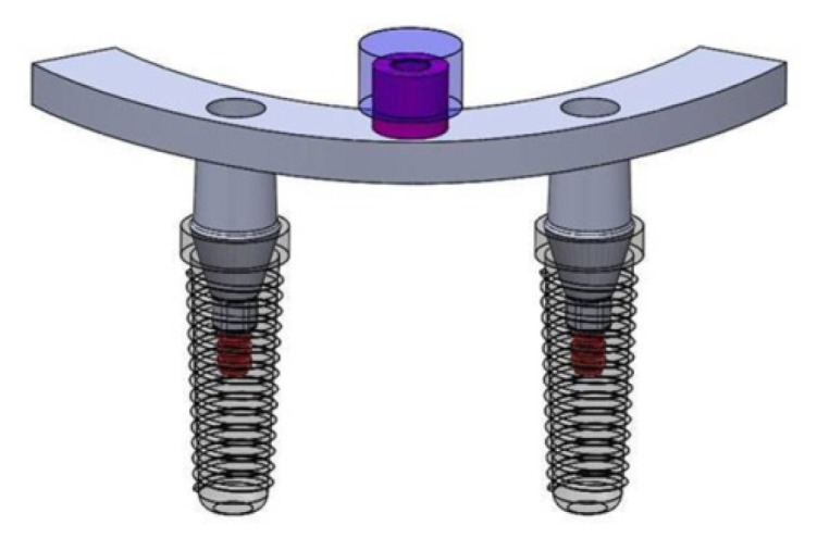
Figure 1.

Implant supported overdenture – 3D model.
Figure 2.

Implant supported overdenture, non-splinted and locator attachments.
Figure 3.

Geometric design of implant supported overdenture, non-splinted and locator attachment.
Figure 4.

Implant supported overdenture, non-splinted and telescopic attachment.
Figure 5.

Geometric design of implant supported overdenture, non-splinted and telescopic attachment.
Figure 6.
Geometric design of implant supported overdenture, splinted attachments.
➢ Implant models
3D, root-form, threaded, titanium dental implant models with locator or telescopic attachments were designed, based on the accurate dimensions and designs collected from the manufacturer (Noble Biocare, Switzerland). The implant models had 3.7 mm diameter, 13 mm length and internal hex connection. They were simulated as titanium alloy (Ti6Al4V).
➢ Bone model
A D2 bone was modeled and a computer tomography scan of the patient mandible used by plotting key points on the Pro/ENGINEER or PTC Creo software. The edentulous mandible was modeled as 2mm constant cortical bone layer around a cancellous bone core in the interforaminal region, whereas in the remaining areas it was assumed to be homogenous.
➢ Locator attachment and nylon cap (dimensions and material properties as per ZEST Anchors, USA)
➢ Telescopic attachment; primary and secondary copings (dimensions and material properties as per Dentsply, ANKYLOS Syncone/5°, USA)
➢ Overdenture (assumed to be polymethylmethacrylate)
➢ Splinted bar for locator and telescopic attachments
The material properties incorporated in the study are represented in Table I. All materials were assumed to be isotropic, homogenous and elastic.
Table I.
Material properties incorporated in the study.
| S.No | Material | Young’s Modulus (GPa) | Poisson’s Ratio | Density |
|---|---|---|---|---|
| 1 | Cortical bone | 13700 | 0.3 | 850–1250 HU (D2 bone) |
| 2 | Cancellous bone | 1370 | 0.3 | - |
| 3 | Titanium alloy (Ti6Al4V-implant) | 135000 | 0.33 | 4.43 g/cm3 |
| 4 | Nylon Ring | 350 | 0.4 | - |
| 5 | Cobalt Chromium | 218000 | 0.33 | 8.5 g/cm3 |
| 6 | Mucosa/Gingiva | 1 | 0.37 | - |
| 7 | Type 3 Gold | 85000 | 0.3 | 15 g/cm3 |
| 8 | Polymethyl Methacrylate (PMMA) | 2400 | 0.35 | 1.19 g/cm3 |
GPa: Gigapascal, g/cm3: Grams per cubic millimeter, HU: Hounsfield unit
All the above models, along with the surrounding alveolar bone and overlying mucosa, were assembled to form a total of 4 clinical simulations.
➢ Implant supported overdenture with non-splinted locator attachment
➢ Implant supported overdenture with splinted locator attachment
➢ Implant supported overdenture with non-splinted telescopic attachment
➢ Implant supported overdenture with splinted telescopic attachment
Discretization process (Figures 7 and 8)
Figure 7.

Meshing of overdenture, non-splinted and locator attachment.
Figure 8.

Meshing of overdenture, splinted locator (A,B) and telescopic attachments (C,D).
This procedure includes creating the mesh, elements with their respective nodes and defining boundary conditions. Meshing divides the body into finite number of elements, each element having nodes. The total number of elements and nodes for each model are mentioned in Table II. As an alternative to the quadratic tetrahedral elements in ABAQUS/Standard (C3D10 or C3D10I), the modified quadratic tetrahedral element (C3D10M) was employed. This element was robust for large-deformation and contact problems using either the traditional node-to-surface or the surface-to-surface contact discretization. It also exhibits minimal shear and volumetric locking.
Table II.
Number of elements and nodes for each model.
| S.No | Component | Element Type | Elements | Nodes |
|---|---|---|---|---|
| 1 | Cortical bone | C3D101 | 133093 | 196993 |
| 2 | Cancellous Bone | C3D101 | 37645 | 66882 |
| 3 | Gingiva | C3D101 | 57360 | 95009 |
| 4 | Implant | C3D101 | 73820 | 110234 |
| 5 | Nylon cap | C3D101 | 15159 | 22838 |
| 6 | Telescopic attachment | C3D101 | 5321 | 8229 |
| 7 | Screw | C3D101 | 38028 | 56653 |
| 8 | Splint | C3D101 | 21650 | 33229 |
| 9 | Denture | C3D101 | 77208 | 115810 |
| Total | 772559 | 503491 | ||
The forces and the boundary conditions were defined to simulate applied loads and constraints of the structure. Boundary conditions reflect the real situation of the displacement produced at each node. It was defined to simulate the real condition by releasing and restraining some nodes from movement or rotation according to the nature of the 3-Dimensional model. In the present study, contacts with friction (coefficient of friction 0.1) were specified. They were introduced between overdenture and mucosa, and between parts of both the selected attachments to simulate the interactions existing between these bodies. Contact within the attachment assemblies was essential to reproduce the behavior of the two retention mechanisms studied. Implants were considered totally osseointegrated, so a mechanically perfect interface was presumed between implants and bone. A vertical compressive load of 35 Newtons was introduced for all the assemblies in the first molar region to simulate occlusal load. A nonlinear contact stress analysis was performed using ABAQUS/Standard and the stress levels were determined. The stress distribution pattern around each implant was provided in the form of 3Dimensional static models made up of the surrounding bone around each dental implant together with the stresses represented by color coded zones; red as maximum and dark blue as minimum. The color and size of each zone represents the stresses occurring within (Von Mises patterns). The values were recorded and tabulated for four different clinical situations.
Ethics approval
The study was reviewed and approved by Ethics Committee of the Army College of Dental Sciences, Secunderabad, India (ACDS/IEC/11/September 2018).
Results
Stress (Table III)
Table III.
Contact stress induced for vertical compressive load of 35 Newtons.
| Stress (in Megapascal) | |||||
|---|---|---|---|---|---|
| S.No | Components | Non-Splinted | Splinted | ||
| Locator | Telescopic | Locator | Telescopic | ||
| 1 | Cortical Bone | 3.73 | 2.66 | 4.12 | 3.7 |
| 2 | Cancellous Bone | 0.295 | 0.49 | 1.17 | 1.05 |
| 3 | Gingiva | 0.14 | 0.138 | 0.21 | 0.22 |
| 4 | Cap | 5.7 | 40.5 | 7.42 | 61.47 |
| 5 | Implant | 2.1 | 8.73 | 25.35 | 24.2 |
| 6 | Attachment | 10.25 | 26.41 | 12.1 | 30.19 |
| 7 | Screw | - | - | 34.5 | 30.89 |
| 8 | Splinted Bar | - | - | 43.32 | 48.36 |
| 9 | Abutment | - | - | 57.65 | 54.22 |
Von Mises stress fields were traced in the form of color-coded bands. The stress distribution in different components were analyzed based on the color-coded bands with red being the highest followed by orange, yellow, light green, green, light blue, blue and dark blue in descending order.
Distribution of stresses in non-splinted attachments (Figures 9 and 10)
Figure 9.

Von Mises stress contour plot- overdenture, non-splinted and locator attachment.
Figure 10.

Von Mises stress contour plot- overdenture, non-splinted and telescopic attachment.
When the non-splinted attachment models were compared, the stress on cortical bone was more with locator attachment when compared to telescopic, whereas on cancellous bone it was more with telescopic. The stress on gingiva showed no difference between the two models. On the other hand, the stress on cap, implant and attachment was more with telescopic attachment when compared to locator.
Distribution of stresses in splinted attachments (Figures 11 and 12)
Figure 11.

Von Mises stress contour plot- overdenture, splinted and locator attachment.
Figure 12.

Von Mises stress contour plot- overdenture, splinted and telescopic attachment.
When the splinted attachment models were compared, the stress on cortical and cancellous bones was more for the locator attachment. The stress on gingiva showed no difference between the two models. On the other hand, the stress on cap, attachments and splinted bars were more with telescopic attachments. The stress on implant and screw were almost similar with locator showing slightly higher values.
Deflection (Table IV)
Table IV.
Deflection for vertical compressive load of 35 Newtons.
| Deflection (in millimeters) | |||||
|---|---|---|---|---|---|
| S.No | Components | Non-splinted | Splinted | ||
| Locator | Telescopic | Locator | Telescopic | ||
| 1 | Cortical Bone | 6.15E-04 | 4.14E-04 | 4.52E-04 | 4.19E-04 |
| 2 | Cancellous Bone | 1.18E-03 | 1.09E-03 | 8.93E-04 | 7.89E-04 |
| 3 | Gingiva | 9.72E-02 | 9.25E-02 | 1.16E-01 | 1.18E-01 |
| 4 | Cap | 1.34E-02 | 8.36E-03 | 2.98E-02 | 5.85E-02 |
| 5 | Implant | 7.61E-04 | 4.58E-04 | 1.11E-03 | 1.00E-03 |
| 6 | Attachment / Attachment on splinted bar | 9.40E-04 | 3.59E-03 | 9.61E-03 | 8.73E-03 |
| 7 | Screw | - | - | 8.63E-04 | 8.11E-04 |
| 8 | Splinted Bar | - | - | 1.88E-02 | 1.77E-02 |
| 9 | Abutment | - | - | 4.82E-03 | 4.45E-03 |
E: Exponential form
When the non-splinted models were compared, the deflection was more with the locator attachment in all the components, except cap. Even in the splinted models, the deflections were more with the locator attachment in all the components, except cap.
Discussion
Proper prosthetic rehabilitation can minimize the bone resorption that occurs after the loss of teeth [11,13]. With the advent and success of osseointegrated dental implant, the concept of IOs has been accepted world wide as a reliable treatment protocol for the management of completely edentulous patients [15–19]. The IOs have become the standard of care because of the greater stability derived from the mechanical attachment retaining the restoration, limited lateral movements that consequently minimize soft tissue trauma [17,26,27].
IOs are subjected to various types of axial and non-axial stresses, including the masticatory forces. The resultant of these forces is transmitted to the implant through the superstructure via the attachments [7]. As the titanium implants are stiffer than natural teeth and as implant–bone interface is rigid, the loads are directly transmitted to the adjacent bone [10]. Thus, the ability of the attachments to dissipate the stresses transmitted by the superstructures influences the prognosis and the success of the implants. In the present study, the tapered implants have been considered for both the attachment systems, as it is reported to provide better stress distribution [16,22].
The techniques like strain gauge, photo-elasticity and FEA have been employed for evaluating the stress distribution in IOs with various attachments [17]. FEA has become an increasingly useful tool for studying the effects of stress on implant and surrounding bone, thus making it an effective computational tool that has been adapted from the engineering arena to dental implants [43]. In the present study, 3D FEA is considered as it is predominantly viewed as the most suitable tool [33–35]; additional advantages being the representation of complex geometries accurately, easy model modifications as well as the depiction of internal stress and other mechanical quantities. Four clinical situations are simulated in the models, splinted and non-splinted implants with locator and telescopic attachments. A nonlinear contact stress analysis was used to analyze the stress pattern, as linear static analysis cannot represent proper physics of the problem, due to complexities involved in analyzing the total assembly with different non-linear contacts. Linear analysis is based on the static and linearity assumptions. When these assumptions fail, linear analysis will produce wrong predictions. Hence, nonlinear analysis is apt to model the nonlinearities of the present design. Amount of force applied on the models in the present study was 35 N. This is because it simulated the bite forces of edentulous patients with overdentures supported by implants in the mandible [34].
During mastication, loads are transferred to alveolar bone surrounding the IOs [34]. The stresses induced by the occlusal loads are initially transferred from the implant to the cortical bone, while a small amount of remaining stresses to the cancellous bone. It has been observed that cortical bone has a greater ability to transfer stress, because of higher elastic modulus [33,34]. A key factor for success or failure of dental implants is dependent on the manner in which stresses are transferred to peri-implant bone. The influence of different types of attachments on peri-implant stress has been investigated [33,35]. In the present study, stress transferred to the cortical bone in splinted and non-splinted locator attachment was more than telescopic attachment. On the other hand, in the components above the mucosa like the caps, implants and attachments, the amount of contact stresses are less with locator attachment than telescopic attachments, indicating a possibility of superior performance and greater prosthesis life span. The time needed between the successive maintenance sessions can also be expected to be less. The stress created on the implant was also less with the locator attachment, 2.1 MPa, as compared to 8.73 MPa for telescopic attachments, which is a clinical advantage. This can be attributed to the geometrical design of locator attachment with smaller height and wider diameter that allows better dissipation of stresses that resulted from the occlusal load application. Another factor is that the material of locator attachment is titanium, whose elastic modulus is 63% more than gold of telescopic attachment [39–42]. Thus, the section modulus, bending resistance, strength and bending moment of inertia are more for locator attachment than telescopic attachment.
When stress patterns generated in splinted and non-splinted models in both the attachment types were compared, stresses were less in non-splinted model. This can be attributed to the fact that, in non-splinted attachment model only vertical compressive forces act. On the contrary, in splinted ones, the combined vertical compressive force along with the bending moment might have created high stress. Also due to the cantilever effect of splinted bar, the deflection was of higher value causing high stresses at the level of the contact zone of the abutment, implant and screw.
The major limitations of the present study are that the stress distribution has been evaluated only under vertical load and consideration of the lowest possible force of 35 N. Another limitation is the assumption of bone as isotropic and homogenous, though the tissue behavior is not. The FEA is a numerical mathematical solution technique, with possible numerical errors and differences in the stresses from one configuration to another. The stress singularities and notch sensitivities in each model might also influence the results. The FEA cannot be used to reproduce the tissue behavior, but can approximate it and provide partially relevant results. Hence, further randomized clinical studies on this topic are needed to draw final conclusions, in spite of the superiority of locator over telescopic attachment as reported in the present study.
Conclusion
- The contact stresses developed on the attachment and implant components were less in the locator model when compared to telescopic, irrespective of splinting procedure. The stresses transferred to the supporting structure, cortical bone, were more with locator attachment compared to the telescopic one, in both non-splinted and splinted models.
- The stresses in all the components of overdenture were greater in the splinted model compared with the non-splinted one, irrespective of the attachment type.
- Thus, from a clinical viewpoint, locator attachment can be considered as a suitable alternative to telescopic for IOs. On the other hand, non-splinted design is preferable when compared to the splinted one.
References
- 1.Peltzer P, Hewlett S, Yawson AE, Moynihan P, Preet R, Fan Wu, et al. Prevalence of loss of all teeth (edentulism) and associated factors in older adults in China, Ghana, India, Mexico, Russia and South Africa. Int J Environ Res Public Health. 2014;11:11308–11324. doi: 10.3390/ijerph111111308. [DOI] [PMC free article] [PubMed] [Google Scholar]
- 2.Reddy NS, Reddy NA, Narendra R, Reddy SD. Epidemiological survey on edentulousness. J Contemp Dent Pract. 2012;13:562–570. doi: 10.5005/jp-journals-10024-1187. [DOI] [PubMed] [Google Scholar]
- 3.Atwood DA, Coy WA. Clinical, cephalometric, and densiometric study of reduction of residual ridges. J Prosthet Dent. 1971;26:280–295. doi: 10.1016/0022-3913(71)90070-9. [DOI] [PubMed] [Google Scholar]
- 4.D’Souza D. Residual ridge resorption – Revisited. Oral health care – Prosthodontics, Periodontology, Biology, Research and Systemic conditions. 2012;2:15–24. [Google Scholar]
- 5.Tallgren A. The continuing reduction of the residual alveolar ridges in complete denture wearers: a mixed-longitudinal study covering 25 years. J Prosthet Dent. 1972;27:120–131. doi: 10.1016/0022-3913(72)90188-6. [DOI] [PubMed] [Google Scholar]
- 6.Anwar A, Kumar B, Akhtar MD, Rahman MZ. Complete denture satisfaction among population in Bihar – A study. IOSR-JDMS. 2015;14:68–72. [Google Scholar]
- 7.Allen PF, McMillan AS. A review of the functional and psychosocial outcomes of edentulousness treated with complete replacement dentures. J Can Dent Assoc. 2003;69:662. [PubMed] [Google Scholar]
- 8.Hantash RO, AL-Omiri MK, Yunis MA, Dar-Odeh N, Lynch E. Relationship between impacts of complete denture treatment on daily living, satisfaction and personality profiles. J Contemp Dent Pract. 2011;12:200–207. doi: 10.5005/jp-journals-10024-1035. [DOI] [PubMed] [Google Scholar]
- 9.Douglass JB, Meader L, Kaplan A, Ellinger CW. Cephalometric evaluation of the changes in patients wearing complete dentures: a 20-year study. J Prosthet Dent. 1993;69:270–275. doi: 10.1016/0022-3913(93)90105-w. [DOI] [PubMed] [Google Scholar]
- 10.Karkazis HC, Lambadakis J. Changes in mandibular alveolar bone and anterior face height after four years of complete denture wearing. Eur J Prosthodont Restor Dent. 1994;2:109–111. [PubMed] [Google Scholar]
- 11.Burns DR. The mandibular complete overdenture. Dent Clin North Am. 2004;48:603–623. v–vi. doi: 10.1016/j.cden.2004.03.002. [DOI] [PubMed] [Google Scholar]
- 12.Chee W, Jivraj S. Treatment planning of the edentulous mandible. Br Dent J. 2006;201:337–347. doi: 10.1038/sj.bdj.4814041. [DOI] [PubMed] [Google Scholar]
- 13.Samra RK, Bhide SV, Goyal C, Kaur T. Tooth supported overdenture. A concept overshadowed but not yet forgotten! J Oral Res Rev. 2015;7:16–21. [Google Scholar]
- 14.Burns DR, Unger JW, Elswick RK, Jr, Beck DA. Prospective clinical evaluation of mandibular implant overdentures: Part I - Retention, stability, and tissue response. J Prosthet Dent. 1995;73:354–363. doi: 10.1016/s0022-3913(05)80331-2. [DOI] [PubMed] [Google Scholar]
- 15.Burns DR. Mandibular implant overdenture treatment: consensus and controversy. J Prosthodont. 2000;9:37–46. doi: 10.1111/j.1532-849x.2000.00037.x. [DOI] [PubMed] [Google Scholar]
- 16.von Wowern N, Gotfredsen K. Implant-supported overdentures, a prevention of bone loss in edentulous mandibles? A 5-year follow-up study. Clin Oral Implants Res. 2001;12:19–25. doi: 10.1034/j.1600-0501.2001.012001019.x. [DOI] [PubMed] [Google Scholar]
- 17.Sadowsky SJ. Mandibular implant-retained overdentures: a literature review. J Prosthet Dent. 2001;86:468–473. doi: 10.1067/mpr.2001.119921. [DOI] [PubMed] [Google Scholar]
- 18.Kordatzis K, Wright PS, Meijer HJ. Posterior mandibular residual ridge resorption in patients with conventional dentures and implant overdentures. Int J Oral Maxillofac Implants. 2003;18:447–452. [PubMed] [Google Scholar]
- 19.Roldan AL, Santolaya AD, Bertomeu IG, Castillo EG, Otaolaurruchi ES. Bone resorption processes in patients wearing overdentures. A 6-years retrospective study. J Clin Exp Dent. 2009;1:24–30. [PubMed] [Google Scholar]
- 20.Mericske-Stern R. Overdentures with roots or implants for elderly patients: a comparison. J Prosthet Dent. 1994;72:543–550. doi: 10.1016/0022-3913(94)90129-5. [DOI] [PubMed] [Google Scholar]
- 21.Bergendal T, Engquist B. Implant-supported overdentures: a longitudinal prospective study. Int J Oral Maxillofac Implants. 1998;13:253–262. [PubMed] [Google Scholar]
- 22.Bhandare V, Dange SP, Khalikar A, Khalikar S. Implant supported overdenture: A step ahead from edentulism. IJOICR. 2015;6:76–81. [Google Scholar]
- 23.Johns RB, Jemt T, Heath MR, Hutton JE, McKenna S, McNamara DC, et al. A multicenter study of overdentures supported by Brånemark implants. Int J Oral Maxillofac Implants. 1992;7:513–522. [PubMed] [Google Scholar]
- 24.Feine JS, Carlsson GE, Awad MA, Chehade A, Duncan WJ, Gizani S, et al. The McGill consensus statement on overdentures. Mandibular two-implant overdentures as first choice standard of care for edentulous patients. Gerodontology. 2002;19:3–4. [PubMed] [Google Scholar]
- 25.Visser A, Raghoebar GM, Meijer HJ, Batenburg RH, Vissink A. Mandibular overdentures supported by two or four endosseous implants. A 5-year prospective study. Clin Oral Implants Res. 2005;16:19–25. doi: 10.1111/j.1600-0501.2004.01085.x. [DOI] [PubMed] [Google Scholar]
- 26.Trakas T, Michalakis K, Kang K, Hirayama H. Attachment systems for implant retained overdentures: a literature review. Implant Dent. 2006;15:24–34. doi: 10.1097/01.id.0000202419.21665.36. [DOI] [PubMed] [Google Scholar]
- 27.Kim HY, Lee YJ, Shin SW, Bryant SR. Attachment systems for mandibular implant overdentures: a systematic review. J Adv Prosthodont. 2012;4:197–203. doi: 10.4047/jap.2012.4.4.197. [DOI] [PMC free article] [PubMed] [Google Scholar]
- 28.Davis DM, Packer ME. Mandibular overdentures stabilized by Astra Tech implants with either ball attachments or magnets: 5-year results. Int J Prosthodont. 1999;12:222–229. [PubMed] [Google Scholar]
- 29.Davis DM, Packer ME. The maintenance requirements of mandibular overdentures stabilized by Astra Tech implants using three different attachment mechanisms--balls, magnets, and bars; 3-year results. Eur J Prosthodont Restor Dent. 2000;8:131–134. [PubMed] [Google Scholar]
- 30.Gotfredsen K, Holm B. Implant-supported mandibular overdentures retained with ball or bar attachments: a randomized prospective 5-year study. Int J Prosthodont. 2000;13:125–130. [PubMed] [Google Scholar]
- 31.Ha SR, Kim SH, Song SI, Hong ST, Kim GY. Implant-supported overdenture with prefabricated bar attachment system in mandibular edentulous patient. J Adv Prosthodont. 2012;4:254–258. doi: 10.4047/jap.2012.4.4.254. [DOI] [PMC free article] [PubMed] [Google Scholar]
- 32.Gotfredsen K, Holm B. Implant-supported mandibular overdentures retained with ball or bar attachments: A randomized prospective 5-year study. Int J Prosthodont. 2000;13:125–130. [PubMed] [Google Scholar]
- 33.Abdelhamid AM, Assaad NK, Neena AF. Three dimensional finite element analysis to evaluate stress distribution around implant retained mandibular overdenture using two different attachment systems. J Dent Health Oral Disord Ther. 2015;2:171–178. [Google Scholar]
- 34.Dashti MH, Atashrazm P, Emadi MI, Mishaeel S, Banava S. The effects of two attachment types on the stressed introduced to the mandibular residual ridge: a 3D finite element analysis. Quintessence Int. 2013;44:585–590. doi: 10.3290/j.qi.a29753. [DOI] [PubMed] [Google Scholar]
- 35.Eltaftazani I, Moubarak A, El-Anwar M. Locator attachment versus ball attachment: 3-dimensional finite element study. Egypt Dent J. 2011;57:73–85. [Google Scholar]
- 36.Evtimovska E, Masri R, Driscoll CF, Romberg E. The change in retentive values of locator attachments and hader clips over time. J Prosthodont. 2009;18:479–483. doi: 10.1111/j.1532-849X.2009.00474.x. [DOI] [PubMed] [Google Scholar]
- 37.Cakarer S, Can T, Yaltirik M, Keskin C. Complications associated with the ball, bar and locator attachments for implant-supported overdentures. Med Oral Patol Oral Cir Bucal. 2011;16:953–959. doi: 10.4317/medoral.17312. [DOI] [PubMed] [Google Scholar]
- 38.Zou D, Wu Y, Huang W, Wang F, Wang S, Zhang Z, et al. A 3-year prospective clinical study of telescopic crown, bar, and locator attachments for removable four implant–supported maxillary overdentures. Int J Prosthodont. 2013;26:566–573. doi: 10.11607/ijp.3485. [DOI] [PubMed] [Google Scholar]
- 39.Oh JR, Woo YH, Lee SB, Bak J. Finite element analysis of stress distribution on telescopic system for mandibular implant supported overdenture. J Korean Acad Prosthodont. 2008;46:359–371. [Google Scholar]
- 40.Krennmair G, Weinländer M, Krainhöfner M, Piehslinger E. Implant-supported mandibular overdentures retained with ball or telescopic crown attachments: a 3-year prospective study. Int J Prosthodont. 2006;19:164–170. [PubMed] [Google Scholar]
- 41.Hoffmann O, Beaumont C, Tatakis DN, Zafiropoulos GG. Telescopic crowns as attachments for implant supported restorations. a case series. J Oral Implantol. 2006;32:291–299. doi: 10.1563/0-815.1. [DOI] [PubMed] [Google Scholar]
- 42.Romanos GE, May S, May D. Treatment concept of the edentulous mandible with prefabricated telescopic abutments and immediate functional loading. Int J Oral Maxillofac Implants. 2011;26:593–597. [PubMed] [Google Scholar]
- 43.Trivedi S. Finite element analysis: a boon to dentistry. J Oral Biol Craniofac Res. 2014;4:200–203. doi: 10.1016/j.jobcr.2014.11.008. [DOI] [PMC free article] [PubMed] [Google Scholar]