Abstract
Laboratory-acquired infections (LAIs) are defined as infections of laboratory staff by exposure to pathogenic microorganisms during an experimental procedure. For a biosafety level-3 (BSL-3) laboratory with a high potential of exposure, reducing risks and threats relevant to LAIs has become a critical concern, especially after the recent outbreak of Novel Coronavirus causing COVID-19 in Wuhan, China. This study aimed to investigate the spatial-temporal characteristics of bioaerosol dispersion and deposition of two kinds of bioaerosols (Serratia marcescens and phage ΦX174). A combination of laboratory experiment and numerical simulation was adopted to explore bioaerosol removal. Three-dimensional concentration iso-surface mapping in conjunction with flow field analysis was employed to elucidate bioaerosol migration and deposition behavior. The total deposition number and unit area deposition ratio were calculated for different surfaces. The results indicate that bioaerosol concentration remains stable for up to 400 s after release, and that almost 70% of all bioaerosol particles become deposited on the surfaces of walls and equipment. Vortex flow regions and high-concentration regions were determined, and the most severely contaminated surfaces and locations were identified. Our results could provide the scientific basis for controlling the time interval between different experiments and also provide guidelines for a laboratory disinfection routine. Furthermore, future work regarding laboratory layout optimization and high efficiency air distribution for bioaerosol removal in a BSL-3 laboratory should be emphasized.
Keywords: Bioaerosol particles, Ventilation, Removal rate, Deposition rate, Biosafety level-3 laboratory
Highlights
-
•
Ventilation efficiency of removing two kinds of bioaerosols was quantitatively examined.
-
•
Removal time for two kinds of bioaerosols in a BSL-3 laboratory was determined.
-
•
The most seriously contaminated locations in a BSL-3 laboratory were explored.
-
•
Guidelines for a BSL-3 laboratory follow-up disinfection routine were proposed.
1. Introduction
Airborne infectious diseases have attracted significant attention worldwide in recent decades due to successive outbreaks of severe acute respiratory syndrome (SARS), Middle East respiratory syndrome (MERS), tuberculosis (TB), and other emerging infections (EIs) [[1], [2], [3], [4], [5], [6], [7]]. In particular, since December 2019, one emerging pneumonia infection COVID-19, caused by the Novel Coronavirus SARS-CoV-2, has spread quickly from Wuhan to the whole of China. Evidence shows that this infectious disease can spread through aerosols [8]. In addition, the risk of accidental exposure during a normal working procedure or emergency issue, such as frequent bioterrorism, have also caused international alert [[9], [10], [11]]. As a result, the need to eliminate pathogenic bioaerosols has been promoted, and a safe environment to avoid the threat of infectious microorganisms and protect human health is essential [12].
A BSL-3 laboratory is mandatory for testing pathogenic bioaerosols and for vaccine development, such as for COVID-19, that display high infectivity [13]. However, such biosafety laboratories could actually become a source of LAIs if they are inappropriately designed and operated. Therefore, our pursuits are aimed at exploring the diffusion of bioaerosols in a BSL-3 laboratory, with the goal of proposing effective control strategies for risk reduction, especially in unexpected situations.
In recent years, a number of studies have been carried out on standard systems, normal management, and risk assessment in biosafety laboratories [14,15]. Some researchers have even employed visualization and CFD technology to investigate the risk of exposure to infections in the laboratory. Barbosa et al. [16] numerically simulated the contaminant contention of a biological safety cabinet (BSC) with different indoor parameters (e.g. inflow velocity, air exchange rate, and room thermal load), and found that increasing the indoor ventilation rate may reduce the control effect of the BSC on pollutants, therefore increasing the risk of exposure. Similarly, Liu et al. [17] utilized a CFD method to study the transport characteristics of gaseous pollutants in a chemical laboratory under different ventilation conditions. They identified the location of the pollution source, the ventilation mode, and the air exchange rate as the three major factors affecting overall ventilation performance. Feng et al. [18] explored the impact of airflow on aerosol protection in the laboratory and found that air distribution pattern was a critical factor in influencing the residence time of bioaerosols, thereby affecting exposure risk.
All of these studies highlight the need to create a safer laboratory environment. However, they all focus only on the impact of ventilation pattern and airflow conditions on bioaerosols or gaseous pollutants, which is not enough. To create a truly safer working environment, more work is needed to identify ways to remove bioaerosols as well as determine the effect of the spatial-temporal characteristics of a typical BSL-3 laboratory layout. Thus, the aim of the current study was to identify the most seriously contaminated locations within a BSL-3 laboratory, as well as to determine the ventilation efficiency for bioaerosol removal, in an effort to develop guidelines for routine laboratory operations. Experiments and numerical simulations were used to explore potential infection risks from exposure to two kinds of bioaerosols, Serratia marcescens and phage ΦX174, in a typical BSL-3 laboratory. The ventilation efficiency of bioaerosol removal was quantitatively examined, and the spatial-temporal characteristics of bioaerosol dispersion and deposition were investigated in depth. In addition, the most contaminated areas and surfaces within the laboratory were identified. Numerical tracking, including both suspended and deposited bioaerosols, was employed to determine migration patterns and deposition mechanisms. A three-dimensional concentration iso-surface map in conjunction with flow field was used to determine the formation of vortex flow regions and high-concentration regions (both in space or on a surface). Our results provide the scientific basis for determining the optimal time interval between different experiments, and will help to devise guidelines for routine follow-up disinfection procedures in the laboratory. The layout of the BSL-3 laboratory used in this study was designed according to the standards of the World Health Organization [19], and therefore all conclusions regarding biological aerosol removal or deposition will be relevant to the operation of other similar BSL-3 laboratories.
2. Methodology
2.1. Physical model
A typical BSL-3 laboratory with dimensions x × y × z = 8 m × 2.5 m × 4 m in Beijing was selected as the physical model (Fig. 1 (a) and (b)). The laboratory was modeled with an up-supply and up-return ventilation mode, which was characterized by a downward airflow into the room from ceiling inlets, then flow out of the room through ceiling outlets after sustained directional movement [20]. According to the experimental investigation, clean air with velocity 0.7 m/s was supplied from two square diffusers measuring 0.63 m × 0.63 m and exhausted from outlets measuring 1.086 m × 0.553 m.
Fig. 1.
(a) Vertical view of BSL-3 laboratory; (b) Field experimental picture in BSL-3 laboratory; (c) Schematic representation of BSL-3 laboratory layout; (d) Locations of sampling points.
Fig. 1(c) shows a schematic representation of the laboratory layout and sampling points in a CFD model with dimensions equivalent to the experimental laboratory. To simplify the analysis and description of relevant details, X+, X-, Z+ and Z-were used to represent the front, rear, left and right walls, along the direction of the main airflow, respectively. This BSL-3 laboratory was equipped with an A2 biosafety cabinet (BSC, 2.5 m × 0.9 m × 2.1 m), as well as six other items of commonly used equipment and two experimental tables (Fig. 1(c)). Each piece of equipment was represented by a rectangular box, which is the general shape of autoclaves, centrifuges, freezers, incubators, and most biological laboratory equipment [16]. The locations of sampling points S1, S2, S3 and S4 are shown in Fig. 1(d), and the dimensions of the laboratory equipment and experimental tables are listed in Table 1 . Due to the particularity of BSL-3 laboratory, there are several considerations for the arrangement of sampling points in this study. First of all, it is not appropriate to select too many sampling points due to the fact that excessive arrangement of measuring equipment may damage the ventilation form. Second, the sampling points should be representative and can cover the typical positions (i.e. source position, two diffusion positions of main flow zone, outlet position) so as to capture the characteristics of pollutant removal path. Finally, several sampling points should be selected at the height of human respiratory zone, which is beneficial to the analysis of subsequent simulations.
Table 1.
Size of laboratory equipment and experimental tables.
| Biosafety Cabinet | Laboratory equipment (1) | Laboratory equipment (2) | Laboratory equipment (3) | Laboratory equipment (4) | Laboratory equipment (5) | Laboratory equipment (6) | Experimental table | |
|---|---|---|---|---|---|---|---|---|
| X(m) | 2.5 | 0.5 | 1 | 0.75 | 0.8 | 0.55 | 0.5 | 3 |
| Y(m) | 2.1 | 0.5 | 1 | 2 | 0.5 | 1.65 | 1.5 | 0.85 |
| Z(m) | 0.9 | 1.45 | 0.5 | 0.85 | 0.5 | 0.55 | 0.5 | 0.5 |
The purpose of this study aims to evaluate the removal effect of bioaerosols and the actual operation effect of sustained directional airflow, because the clean air control scope and real operation effect were often affected by experiment layouts. Therefore, for better analyses, the contaminant source was placed in the clean zone (below the inlet). The bioaerosol diffusion and deposition rules obtained under this adverse scenario has more important guiding significance for the operation of an actual biosafety laboratory.
In addition, specific operation policies implemented in a BSL-3 laboratory are illustrated because operating characteristics during the experiment were relevant to the collection of experimental data and simulation settings. The interval between experiments was about 30 min, and included ventilation and evacuation (5 min), fumigation and disinfection (10 min), wiping and disinfection of key areas (5 min), ventilation and evacuation (5 min) and system inspection (5 min).
2.2. Numerical model
A numerical model was built based on the actual laboratory size and room layout. In addition, relevant simulation settings were set according to the actual airflow form and boundary conditions. All parameters (i.e. source concentration, diameter, release speed, and position) of the two bioaerosols in the simulation were based on experimental data and were carefully verified.
According to previous reports, a typical laboratory environment has low velocity, incompressible, and turbulent fluid characteristics [21]. As a consequence, airflow can be regarded as a continuous fluid and can be represented by the Euler conservation equation [22]. In the current study, CFD simulations were carried out using ANSYS Fluent 17.0, and grids of the model were built by GAMBIT. The supply air diffusers were defined as a velocity-inlet boundary, pressure was specified at the outlets and a no-slip boundary condition was applied to the surfaces (i.e. walls, ceiling, ground, and equipment). After comprehensive consideration of simulation reliability and resource utilization, the N-point air supply opening model [23] and a standard k-ε model were used to generate the turbulence model [24]. Meanwhile, the standard wall function was adopted [25], the second order upwind scheme was used for all variables, and the SIMPLE algorithm used to calculate the flow field. Based on the Lagrangian viewpoint, a particle tracking model was established to simulate the motion of spherical particles in continuous fluid. According to the basic theories of aerosol mechanics [26], gravity, drag force, thermophoretic force (non-isothermal), Saffman force, pressure gradient force, magnus force, and virtual mass force of particles must be considered when computing particle motion. Normally, the pressure gradient force, magnus force, and virtual mass force are very small compared to other forces, and are often neglected [27]. In addition, the isothermal boundary condition was employed in this simulation, therefore the effect of thermophoretic force was not considered. In summary, the equation of motion takes into account significant factors affecting particle motion including drag force , gravity and Saffman force and is defined in Equation (1).
| (1) |
Drag force is defined as:
| (2) |
where is the molecular dynamic viscosity of the air, is the particle density, is the particle diameter, is the fluid drag coefficient, is the particle Reynolds number, is the air velocity, and is the particle velocity.
All objects are attracted by gravity, and gravitational deposition becomes more important as particle size increases. The gravity of the particles was defined as:
| (3) |
Bioaerosol particles in a shear flow field may be subjected to a force perpendicular to the mainstream. The lift of particles in a long shear flow field far from a wall is calculated using the Saffman force:
| (4) |
where is the air velocity gradient perpendicular to the wall surface, and is the axial velocity of the particle.
In the present study, a one-way coupling Lagrangian approach was used to calculate the diffusion of all bioaerosol particles. Moreover, the discrete random walk (DRW) model was used to determine the effect of turbulence on particle diffusion. When particle concentration is low, the simulation assumes that the effect of particles on flow field is negligible. In addition, the following assumptions were used in this study:
-
(1)
The up-supply and up-return ventilation mode was taken and the particle volume fraction in the environment was much smaller than Elghobashi's given criterion (less than 10−6) [28]. Thus, the effect of particle settling velocity on turbulence can be considered negligible compared to the high inflow turbulence level of the indoor environment.
-
(2)
The experimental results showed that indoor temperature was basically stable at 22 ± 1 °C. Therefore, the influence of a heat source on bioaerosol deposition or airflow is negligible in this model [29].
-
(3)
According to results of Hinds [30], the concentration will be halved by solidification only after more than 200 days. Therefore, it was assumed that there was no collision or solidification between the particles.
-
(4)
The bioaerosol particles were assumed to be completely reserved on the surface when in contact with the floor, wall, ceiling or equipment, due to the fact that the boundary conditions of solid surfaces in real laboratories exhibit relatively high absorption and the selected particle size was too small. In fact, the wall condition was set as a “trap” [26,31].
-
(5)
According to Wei et al. [32], the evaporation time of small particles is very short and the evaporation time of 1 μm particles is about 0.0006–0.0031 s. A similar conclusion was drawn by Morawska [33], therefore we determined that evaporation effect would negligible in our simulation due to the small size of the selected bioaerosols.
The following criteria were exercised for the simulation work of this study. First, the simulation work has been repeated multiple times under same boundary conditions. Secondly, the simulation and the experimental results were verified by spatial concentration, and the results were acceptable. Therefore, the conclusions of subsequent simulations are considered to be stable and reliable.
2.3. Bioaerosols parameters
Both Serratia marcescens and phage ΦX174 were selected to represent high-risk microorganisms in the present study. The bioaerosol source was 0.1 m in front of S1, and bioaerosol particles were produced at the start of the experiment using a single aerosol generator. Total particle concentration at the source was tested at 10 min after release using an Aerodynamic Particle Sizer (APS 3321), and four six-stage Andersen samplers (i.e. S1, S2, S3 and S4) were used to collect bioaerosols at each sampling point. During the experimental process, sampling flow settings were all set to 28.3 L/min, and time settings were 0.5 min for S1, 5 min for S2, and 10 min for S3 and S4. Under the condition of convergence, the time step of numerical simulation was gradually increased from 0.1s to 1s. Based on this, the tracking simulation was set to 900 s to ensure that all particles were deposited or removed.
The experimental process for the two types of bioaerosols were consistent and the parameters are shown in Table 2 . It is worth mentioning that the chosen release speed of 0.53 m/s was based on a bioaerosol flux of 10 L/min, and the amount of bioaerosol particles used in the CFD model was based on experimental data to ensure accuracy of the simulations. The bioaerosol diameter used in this study was the median aerodynamic particle size calculated by the APS 3321. Relevant sampling results and particle size distribution are shown in Fig. 2 .
Table 2.
Parameters of Serratia marcescens and phage ΦX174 (used for CFD model).
| Diameter (μm) | Measuring time point | Relative humidity | Amount (CFU/m3) | Density (kg/m3) | Releasing speed (m/s) | Source location | |
|---|---|---|---|---|---|---|---|
| Serratia marcescens | 0.760 | 10 min after release | 20% | 932173 | 1000 | 0.53 | 0.1 m distance of S1 |
| Phage ΦX174 | 0.696 | 10 min after release | 21% | 878862 | 1000 | 0.53 | 0.1 m distance of S1 |
Fig. 2.
Particle counts and size distribution from the Aerodynamic Particle Sizer (APS 3321): (a) Serratia marcescens (b) Phage ΦX174.
3. Validation of numerical model
A structured grid in a Cartesian coordinate system was employed to build a numerical model of the BSL-3 laboratory. Grid structure and density have been shown to significantly affect the simulation results of a flow field [[34], [35], [36]], therefore a grid independence test of the BSL-3 laboratory was undertaken. Compared with a nominal grid size of 50 mm, 25 mm and 20 mm, three sets of grid configurations (554857, 2077985 and 4065482) were tested and all were encrypted where the velocity gradient was large [37]. Grid sensitivity was verified by the velocity variation at different heights below Inlet1 and Outlet1, as well as from a comparison between experimental and simulation results. The variation in velocity between 20 mm and 25 mm grids was very small, and the curve of the 25 mm grids was closer to the measured results (Fig. 3 ). Therefore, a grid size of 25 mm was selected for all subsequent simulations and analyses in this study.
Fig. 3.
Sensitivity of velocity to grid for three grids below Inlet 1 and Outlet 1.
The flow field in this model was verified to ensure accuracy of the numerical calculation of the continuous phase fluid. Since the motion of bioaerosol particles is primarily affected by airflow, an accurate model of continuous phase fluid is essential for exploring bioaerosol diffusion. From this, various air velocities at different heights (along a straight line) directly below four diffusers (two inlets and two outlets) were selected and compared between numerical simulations and field measurements (Fig. 4 ). Results show that the experimental and numerical velocity data are in agreement. The mean absolute percentage error (MAPE) for velocity was less than 10% [38], suggesting that the boundary condition settings of the flow field are reasonable. The top-right corner of Fig. 4 shows the plane velocity field measurements at 0.1 m below the inlets, which is very close to the diffusers. Due to the characteristics of the diffusers, the fluctuation in air velocity at this position made it difficult to accurately capture the instantaneous velocity. However, after performing error analysis, the velocity deviation between numerical and measurement results for supply air was also less than 10%. Therefore, the air supply in the model can be considered acceptable.
Fig. 4.
Inlet and outlet air velocity verification: comparison between experiment and simulation.
One inevitable deviation in velocity pattern might be caused by a combination of systematic deviation due to anemometer operation, simplification of diffusers in the CFD model, and difficulty in capturing velocity near the wall boundary. However, a deviation analysis of the whole simulation indicated that these were all within the acceptable range of the analysis.
To better track or predict the spread of bioaerosol particles in a typical BSL-3 laboratory, a bioaerosol release experiment was performed. Anderson samplers and plate counting method were used to obtain the colony-forming number of viable microorganisms, and then the concentration value of airborne culturable bioaerosols was calculated by Equation (5). The source concentration in the simulation was converted based on the concentration of viable microorganisms obtained by Anderson sampler, so all particles in the simulation were assumed to be viable. In addition, the growth, reproduction and death characteristics of the bioaerosol diffusion process in the simulation could be neglected due to the short time in the air.
| (5) |
where C is the airborne culturable microbial concentration, m is the dilution multiple, N is colony number, F is the sampling flow rate, and T is the sampling time.
Sampling data for two kinds of bioaerosols at each point (S1, S2, S3 and S4) are shown in Table 3 . The experiments repeated 5 times for each sampling point. The initial concentration used in the numerical calculation model and the verification data were based on these values. Due to the uncertainty of measurements from the six-stage Andersen sampler, the data for Serratia marcescens in group 5 differed greatly from those for the other groups. These data were therefore excluded and the Serratia marcescens concentration was determined using the average from the first four groups only.
Table 3.
Sampling data for Serratia marcescens and phage ΦX174 at each point. (All data in the table was calculated and converted on the basis of Equation (5). The consistency of S1-phage data between group 2 and group 4, group 3 and group 5 is due to the same number of PFU observed).
| Species & Point |
Serratia marcescens (CFU/m3) |
Phage ΦX174 (PFU/m3) |
||||||
|---|---|---|---|---|---|---|---|---|
| S1 | S2 | S3 | S4 | S1 | S2 | S3 | S4 | |
| Group 1 | 933074 | 5915 | 3435 | 293 | 1051270 | 84601 | 8198 | 343 |
| Group 2 | 930318 | 4982 | 2519 | 283 | 557173 | 87018 | 4424 | 452 |
| Group 3 | 931731 | 4339 | 2954 | 216 | 1114346 | 84163 | 5537 | 473 |
| Group 4 | 933569 | 4608 | 1837 | 269 | 557173 | 85385 | 6929 | 548 |
| Group 5 | 467350 | 5477 | 2710 | 452 | 1114346 | 82855 | 3481 | 378 |
| Average | 932173 | 4961 | 2686 | 265 | 878862 | 84804 | 5714 | 439 |
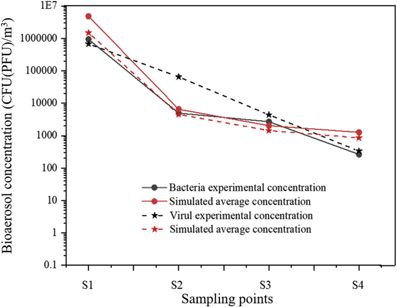
Fig. 5 shows the concentration verification for two kinds of bioaerosols, where the curves represent the trend of measured and simulated bacteria and virus concentrations at four sampling points. The experimental concentration correlated with the simulated average concentration, and the simulation values for bacteria and virus were similar. The concentration verification results indicate that the numerical prediction is highly consistent with the experimental data, which demonstrates the validity of subsequent simulations.
Fig. 5.
Concentration verification of two kinds of bioaerosols in experiment and simulation.
4. Results and discussion
Based on the above-mentioned verifications, the efficiency of the ventilation at removing bioaerosols in the BSL-3 laboratory was first analyzed, followed by the migration pattern of the bioaerosols, and then the formation mechanism of a high-concentration region. Finally, the deposition characteristics and mechanisms of bioaerosols will be discussed.
4.1. Ventilation efficiency of bioaerosol removal in a BSL-3 laboratory
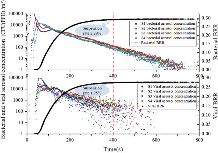
Fig. 6 shows the decreasing trend of bioaerosol concentration at spatial sampling points and the bioaerosol removal rate (BRR) for both bioaerosols based on the simulation, which reflects the bioaerosol-removing characteristics. At S1, the concentration of both bioaerosols reached a maximum at 25–35 s and then decreased significantly, whereas the concentration at S2 increased gradually. This suggests that bioaerosols would be dominated by directional airflow towards S1, but would soon be directed to S2 after about 5 s due to the fact that the bioaerosol release from the source was set as a one-time rather than continuous release. Subsequently, it was also noticed that the concentrations at S3 and S4 reached their peak at 40–50 s, but only about 1/100 of the original amount remained at this time. It can therefore be concluded that there was significant non-directional diffusion of bioaerosol particles after passing through S2, as explained by the interference of vortex flow by obstacles. When the directional airflow encountered an obstacle, it would cause boundary layer separation and form turbulent zones of varying degrees, thereby reducing the bioaerosol particle carrying capacity of the directional airflow, causing some to fall off the airflow. This conclusion was confirmed later. The concentration of phage ΦX174 was slightly different from that of Serratia marcescens, but their removal efficiencies were similar. This finding shows that differences in size and mass between the two bioaerosols led to slightly different airflow follow-ability, but there was no significant difference in the trend of their decrease. Therefore, only Serratia marcescens was used in later analyses of bioaerosol migration and deposition.
Fig. 6.
Concentration variation of bioaerosols with time at each sampling point and BRR (bioaerosol removal rate) of air outlets.
The bioaerosol removal rate (BRR) refers to the ratio of the amount removed through the outlets to the original released amount and was used to evaluate the removal efficiency of bioaerosol particles in a biosafety laboratory. Results show that the removal rate for the two bioaerosols tended to stabilize after 400 s, and both were below 30% (29.5% for Serratia marcescens and 28% for phage ΦX174). As can be seen in Fig. 6, the suspension rate of residual bioaerosols in space was 2.29% and 1.95% at that time, and the proportion that attached to or settled on indoor surfaces was close to 70% for both particles. Thus, under the influence of bioaerosol characteristics and indoor obstacles, nearly 70% of bioaerosol particles became deposited on various surfaces, including the wall, ground, ceiling, equipment, and tables during movement with the airflow. It is therefore possible that these deposited bioaerosol particles may greatly increase the exposure risk in the laboratory.
4.2. Migration of bioaerosols and mechanism of formation of a high-concentration region
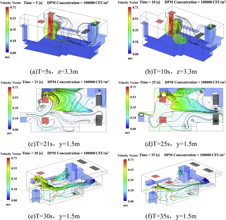
After investigating the motion of bioaerosol particles, it was clear that airflow was the main factor determining their trajectory. Since the BLS-3 laboratory was modeled with an up-supply and up-return ventilation mode, it can be predicted that bioaerosol particles will undergo complex migration in three-dimensional space under the function of airflow combined with obstacles. To visualize the spread of bioaerosol particles under the control of airflow, three-dimensional concentration iso-surface maps were employed to determine migration characteristics.
Fig. 7 illustrates the migration pattern of bioaerosol particles in the BSL-3 laboratory with a velocity streamline map and a three-dimensional concentration iso-surface map. After bioaerosol particles are released from the source, they would be controlled by the vertical airflow and moved downward. Ten seconds later, a cloud of high-concentration particles would hit the ground and move in two directions, as affected by airflow on the ground. Next, some of the particles were seen to move below experimental Table 1, while the others moved toward the two outlets. The former particles were captured by surfaces and caused rapid attenuation, then escaped from the experimental table and gradually moved upwards with the updraft before eventually being adsorbed onto the surface of equipment 3. The latter particles were carried by the airflow toward the outlets where most would be deposited on the ground. The entire process took about 30 s and is described in detail in Fig. 7(a)–(e). It was also seen that under the influence of vortex flow regions, several high-concentration regions still existed in space after 35 s (Fig. 7(f)).
Fig. 7.
Iso-surface map of concentration and velocity streamline maps at different sections, DPM Concentration = 100000 CFU/m.3.
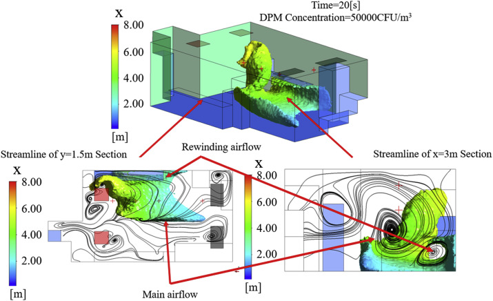
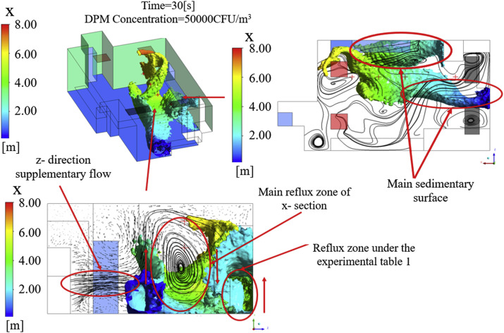
Fig. 8, Fig. 9 explain the formation mechanism of high-concentration regions with velocity streamline maps of typical cross-sections. They show that the trajectory of bioaerosol particles is mainly affected by the movement of the main airflow and is consistent with previous data. However, a number of vortex flow regions of different scales were also observed that were due to obstruction by laboratory equipment or the internal interaction of airflow. The reflux zone under experimental Table 1 and the main reflux zone of the X-section were the two main vortex flow regions. The former was caused by obstruction from the wall and table when the airflow moved below experimental Table 1, resulting in rewinding airflow, while the latter was a clockwise rotating airflow produced by an interaction between the Z-direction supplementary flow and the main airflow. Both of these can weaken the particle carrying capacity of the airflow and cause bioaerosol particles to fall out and remain for a length of time, thus forming high-concentration residual regions.
Fig. 8.
Iso-surface maps of concentration and velocity streamline maps at different cross-sections, DPM Concentration = 50000 CFU/m3, T = 20 s.
Fig. 9.
Iso-surface maps of concentrations and velocity streamline maps at different cross-sections, DPM Concentration = 50000 CFU/m3, T = 30 s.
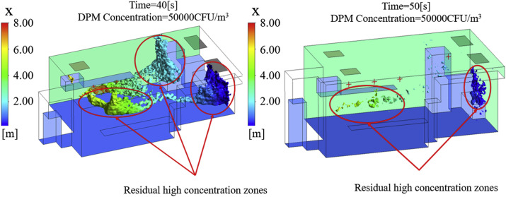
As shown in Fig. 10 , high-concentration residual regions formed in three main locations: the side of equipment 3, the lower half of the X-wall, and a small region below the inlets. After the process of surface capture and ventilation removal at T = 50 s, the high-concentration regions were obviously reduced, and only a small region below the inlets and on the lower half of the X-wall remained. These results show that migration of the cloud of high-concentration particles was consistent with the direction of airflow, while the high-concentration regions were closely related to the vortex flow regions. Thus, it can be concluded that equipment layout is a critical factor in the particle carrying capacity of directional airflow, and thereby the risk of exposure to bioaerosols in the laboratory.
Fig. 10.
Iso-surface maps of DPM Concentration = 50000 CFU/m3, T = 40 s and 50 s.
4.3. Deposition characteristics and mechanism of bioaerosols in a BSL-3 laboratory
From our bioaerosol migration data, it is clear that the risk of exposure to bioaerosols in a BSL-3 laboratory comes mainly from deposition pollution. There were, however, obvious differences in the spatial-temporal characteristics of deposition between different surfaces, and it was therefore necessary to conduct further in-depth analysis.
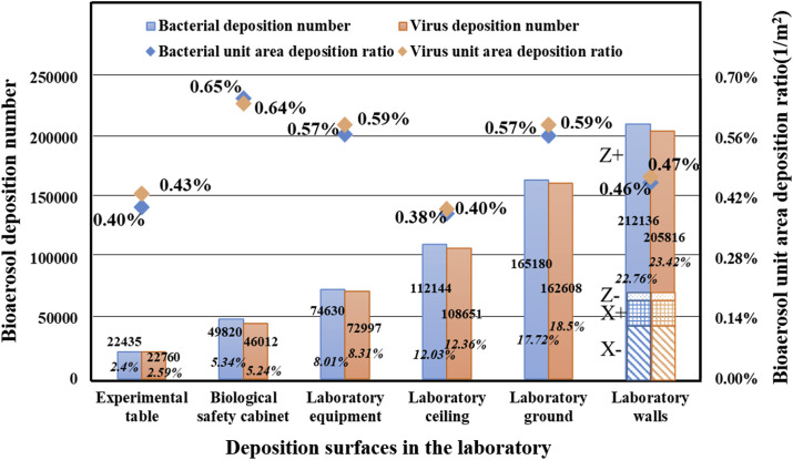
The sedimentation statistics of both bioaerosols on different surfaces (including ceiling, ground, walls, laboratory equipment, and tables) are shown in Fig. 11 , and the deposition ratio and unit area deposition ratio of bioaerosols for each surface are also given. The deposition ratio is defined as the percentage of total deposition particles on all surfaces to the original released amount. The unit area deposition ratio was introduced to systematically compare the concentration of bioaerosol particles on different surfaces. Their mathematical models are defined by Equation (6) and Equation (7).
| (6) |
| (7) |
where is the deposition ratio of equipment or table, r is the surface with potential for sedimentary particles, N i is the deposition number on surface i, A is the released amount, is the unit area deposition ratio of equipment or table, and S i is the area of deposition surface i.
Fig. 11.
Sedimentation statistics for both bioaerosols on different surfaces (ceiling, ground, walls, laboratory equipment, and tables).
The above parameters reflect the degree of pollution for each surface to a certain extent. We found that more than 50% of bioaerosol particles were deposited on the inner surface of the building: about 22.76% on the walls, 17.72% on the ground, and 12.03% on the ceiling. It is therefore worth noting that the cleanliness of the building envelope deserves attention when performing biosafety experiments, rather than being ignored. However, taking into consideration differences in surface area, the unit area deposition ratios of the biological safety cabinet (BSC), laboratory equipment, and floor were higher than for other surfaces (0.65%/m2, 0.57%/m2, 0.57%/m2, respectively). These results indicate that surfaces are more likely to enhance deposition pollution due to airflow, even though the surface area of some equipment is small. Thus, careful disinfection of the surfaces of laboratory equipment should be emphasized.
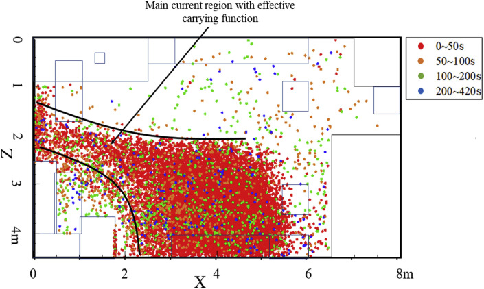
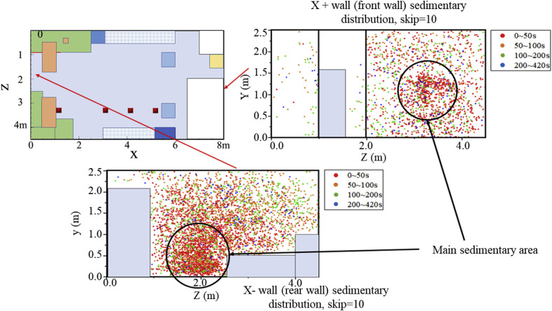
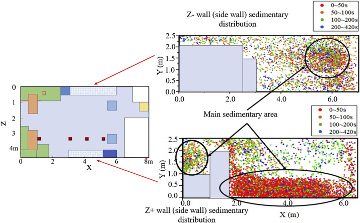
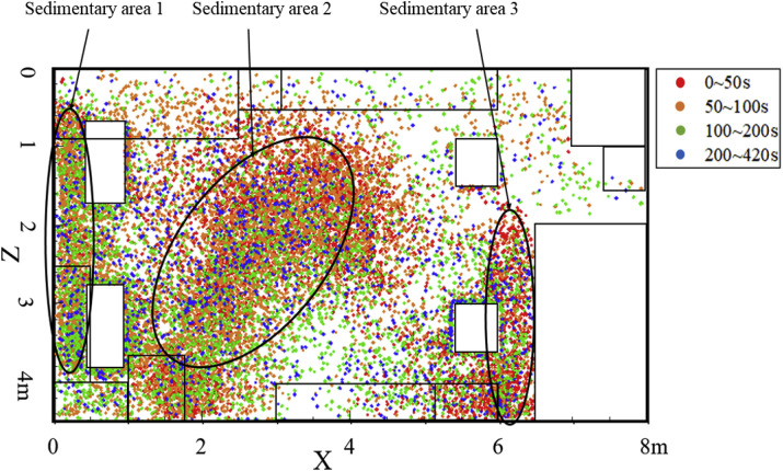
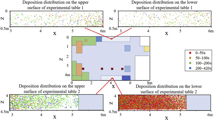
To further explain the deposition mechanism of bioaerosol particles, an exploration of the main sedimentary area of some typical surfaces in the laboratory was carried out. Fig. 12, Fig. 13, Fig. 14, Fig. 15, Fig. 16 show bioaerosol deposition at different times on the walls, ground, ceiling, laboratory equipment, and experimental tables. In particular, Fig. 13 shows the presence of highly concentrated particles, a large number of which coincided, making it difficult to highlight the sedimentary distribution. Therefore, the number of deposited particles was reduced in proportion and skip = 10 represents only 1/10 of the actual particles.
Fig. 12.
Distribution of bioaerosol deposition on the ground after different time periods.
Fig. 13.
Distribution of bioaerosol deposition on X- and X+ walls after different time periods.
Fig. 14.
Distribution of bioaerosol deposition on Z- and Z+ walls after different time periods.
Fig. 15.
Distribution of bioaerosol deposition on the ceiling after different time periods.
Fig. 16.
Distribution of bioaerosol deposition on upper and lower surfaces of the experimental tables after different time periods.
Fig. 12 shows the deposition distribution on the ground, and the main sedimentary area was located in the banded area between the source and the outlets. Combining this finding with the airflow analysis described in the previous section reveals that the sedimentary area would completely coincide with the coverage area of the main airflow with particle carrying capacity.
Fig. 13, Fig. 14 show the distribution of bioaerosol deposition on the surrounding walls. The amount of bioaerosol deposition on the X-wall was greater than on the X+ wall, which was mainly determined by the direction of the main airflow (Fig. 13). Moreover, most of the deposition occurred in the first 50 s, which is consistent with the migration time of high-concentration regions to the outlets. Similar results were found for the other walls: the amount of deposition on the Z+ sidewall was much greater than on the Z-wall, and the main sedimentary area was located below experimental Table 1 (Fig. 14). This was due to the fact that the vortex flow region under experimental Table 1 was close to the release source, thus carrying a large number of bioaerosols that remained for a long time. There was also a small main sedimentary area on equipment 2, and again it can be shown that bioaerosol particles carried in the vortex flow are not carried out of the room and eventually become deposited on the wall near the vortex flow regions.
Fig. 15 shows the distribution on three sedimentary areas on the ceiling, where bioaerosol particle deposition is mainly related to the indoor updraft. In addition, it was found that there were relatively more deposited particles on the ceiling. This could be explained by the strong lift of the updraft with a certain particle carrying capacity and could be enhanced by the presence of equipment under the up-supply and up-return ventilation mode.
Fig. 16 shows the deposition distribution on the upper and lower surfaces of the experimental tables. Due to the low and narrow space under experimental Table 1, the bioaerosol particles were not effectively discharged with the airflow, but instead repeatedly collided with obstacles, resulting a large amount of deposition. Through a detailed analysis of the deposited particles on each surface, we showed that the deposition distribution of bioaerosols is closely related to the airflow characteristics, and the area near the vortex flow region was found to be the most seriously contaminated area.
5. Conclusions
The aim of the present study was to investigate the migration and deposition characteristics of bioaerosol particles in a BSL-3 laboratory by focusing on three aspects: removal efficiency, removal time, and deposition distribution of bioaerosols. Consistent experimental results confirmed the validity of the CFD simulation. The main conclusions of the study are as follows:
-
(1)
There was no obvious difference in the removal efficiency of two kinds of bioaerosol in the BSL-3 laboratory. Almost 70% of bioaerosol particles became deposited on the surface of walls and equipment, leading to a high potential risk of laboratory-acquired infection. Therefore, it is necessary to pay close attention to follow-up laboratory disinfection routines.
-
(2)
The removal rates for both types of bioaerosol showed that they tended to stabilize after 400 s, which provides a scientific basis for regulating the time interval between different experiments.
-
(3)
Bioaerosol migration patterns indicate that high-concentration regions form mainly within vortex flow regions. Obstacles in the laboratory, such as equipment and tables, can influence the indoor flow field and increase the residence time of bioaerosols. Therefore, it is necessary to optimize the layout of laboratory equipment to improve the efficiency of bioaerosol removal.
-
(4)
In this BSL-3 laboratory, more than 50% of bioaerosols were deposited on the walls (22.76%), ground (17.71%) and ceiling (12.03%). Moreover, the unit area deposition ratio of bioaerosols for the biosafety cabinet, laboratory equipment, and ground was 0.65%/m2, 0.57%/m2, and 0.57%/m2, respectively, indicating that there is a higher potential for bioaerosol deposition on the surface of laboratory equipment. Therefore, disinfection of the surfaces of laboratory equipment is extremely important.
In summary, the potential infection risk from exposure to bioaerosols in a BSL-3 laboratory was investigated in detail using experimental and simulation methods. The results provide a scientific basis for controlling the time interval between different experiments and also provide guidelines for routine laboratory disinfection protocols. Future studies should be focused on optimizing the laboratory layout and improving the air distribution for efficient removing of bioaerosol.
Declaration of competing interest
The author(s) declared no potential conflicts of interest with respect to the research, authorship, and/or publication of this article.
Acknowledgment
This work was funded by the National Natural Science Foundation of China (No. 41977368, 51708211), the National Science and Technology Ministry of China (2016YFC1201302), and Fundamental Research Funds for the Central Universities (No.2020YJ007).
References
- 1.Yu I.T.S., Wong T.W., Chiu Y.L., Lee N., Li Y. Temporal-spatial analysis of severe acute respiratory syndrome among hospital inpatients. Clin. Infect. Dis. 2005;40(9):1237–1243. doi: 10.1086/428735. [DOI] [PMC free article] [PubMed] [Google Scholar]
- 2.Qian H., Li Y., Nielsen P.V., Huang X. Spatial distribution of infection risk of SARS transmission in a hospital ward, Build. Environ. Times. 2009;44(8):1651–1658. doi: 10.1016/j.buildenv.2008.11.002. [DOI] [Google Scholar]
- 3.Zhu S., Demokritou P., Spengler J. Experimental and numerical investigation of micro-environmental conditions in public transportation buses. Build. Environ. 2010;45(10):2077–2088. doi: 10.1016/j.buildenv.2010.03.004. [DOI] [PMC free article] [PubMed] [Google Scholar]
- 4.Hathway E.A., Noakes C.J., Sleigh P.A., Fletcher L.A. CFD simulation of airborne pathogen transport due to human activities. Build. Environ. 2011;46(12):2500–2511. doi: 10.1016/j.buildenv.2011.06.001. [DOI] [PMC free article] [PubMed] [Google Scholar]
- 5.Tang J.W., Noakes C.J., Nielsen P.V., Eames I., Nicolle A., Li Y., Settles G.S. Observing and quantifying airflows in the infection control of aerosol- and airborne-transmitted diseases: an overview of approaches. J. Hosp. Infect. 2011;77(3):213–222. doi: 10.1016/j.jhin.2010.09.037. [DOI] [PMC free article] [PubMed] [Google Scholar]
- 6.Azimi P., Stephens B. HVAC filtration for controlling infectious airborne disease transmission in indoor environments: predicting risk reductions and operational costs. Build. Environ. 2013;70:150–160. doi: 10.1016/j.buildenv.2013.08.025. [DOI] [PMC free article] [PubMed] [Google Scholar]
- 7.Liu Z., Ma S., Cao G., Meng C., He B.J. Distribution characteristics, growth, reproduction and transmission modes and control strategies for microbial contamination in HVAC systems: a literature review. Energy Build. 2018;177:77–95. doi: 10.1016/j.enbuild.2018.07.050. [DOI] [Google Scholar]
- 8.Wu J.T., Leung K., Leung G.M. Nowcasting and forecasting the potential domestic and international spread of the 2019-nCoV outbreak originating in Wuhan, China: a modelling study. Lancet. 2020 doi: 10.1016/S0140-6736(20)30260-9. [DOI] [PMC free article] [PubMed] [Google Scholar]
- 9.Pedrosa P.B.S., Cardoso T.A.O. Viral infections in workers in hospital and research laboratory settings: a comparative review of infection modes and respective biosafety aspects. Int. J. Infect. Dis. 2011;15(6):e366–e376. doi: 10.1016/j.ijid.2011.03.005. [DOI] [PMC free article] [PubMed] [Google Scholar]
- 10.D'Amelio E., Gentile B., Lista F., D'Amelio R. Historical evolution of human anthrax from occupational disease to potentially global threat as bioweapon. Environ. Int. 2015;85:133–146. doi: 10.1016/j.envint.2015.09.009. [DOI] [PubMed] [Google Scholar]
- 11.Artika I.M., Ma'roef C.N. Laboratory biosafety for handling emerging viruses. Asian Pac. J. Trop. Biomed. 2017;7(5):483–491. doi: 10.1016/j.apjtb.2017.01.020. [DOI] [PMC free article] [PubMed] [Google Scholar]
- 12.Li N., Hu L., Jin A., Li J. Biosafety laboratory risk assessment. J. Biosaf. Biosecur. 2019 doi: 10.1016/j.jobb.2019.01.011. [DOI] [Google Scholar]
- 13.Huang C., Wang Y., Li X., Ren L., Zhao J., Hu Y., Zhang L., Fan G., Xu J., Gu X., Cheng Z., Yu T., Xia J., Wei Y., Wu W., Xie X., Yin W., Li H., Liu M., Xiao Y., Gao H., Guo L., Xie J., Wang G., Jiang R., Gao Z., Jin Q., Wang J., Cao B. Clinical features of patients infected with 2019 novel coronavirus in Wuhan, China. Lancet. 2020;395(10223):497–506. doi: 10.1016/S0140-6736(20)30183-5. [DOI] [PMC free article] [PubMed] [Google Scholar]
- 14.Zaki A.N. Biosafety and biosecurity measures: management of biosafety level 3 facilities. Int. J. Antimicrob. Agents. 2010;36:S70–S74. doi: 10.1016/j.ijantimicag.2010.06.026. [DOI] [PubMed] [Google Scholar]
- 15.Magnuson M., Campisano R., Griggs J., Fitz-James S., Hall K., Mapp L., Mullins M., Nichols T., Shah S., Silvestri E., Smith T., Willison S., Ernst H. Analysis of environmental contamination resulting from catastrophic incidents: Part 2. Building laboratory capability by selecting and developing analytical methodologies. Environ. Int. 2014;72:90–97. doi: 10.1016/j.envint.2014.01.021. [DOI] [PubMed] [Google Scholar]
- 16.Barbosa B.P.P., Brum N.D.C.L. Sensitivity tests of biological safety cabinets' contaminant contention to variations on indoor flow parameters in biosafety level laboratories. Build. Environ. 2017;124:1–13. doi: 10.1016/j.buildenv.2017.07.034. [DOI] [Google Scholar]
- 17.Liu W., Liu D., Gao N. CFD study on gaseous pollutant transmission characteristics under different ventilation strategies in a typical chemical laboratory. Build. Environ. 2017;126:238–251. doi: 10.1016/j.buildenv.2017.09.033. [DOI] [Google Scholar]
- 18.Feng X., Zhang Y., Xu Z., Song D., Cao G., Liang L. Aerosol containment by airflow in biosafety laboratories. J. Biosaf. Biosecur. 2019;1(1):63–67. doi: 10.1016/j.jobb.2018.12.009. [DOI] [Google Scholar]
- 19.World Health Organization . third ed. 2015. Laboratory Biosafety Manual.http://www.who.int/csr/delibepidemics/WHO_CDS_CSR_LYO_2004_11/en/ [Google Scholar]
- 20.Tian Z.F., Tu J.Y., Yeoh G.H., Yuen R.K.K. On the numerical study of contaminant particle concentration in indoor airflow. Build. Environ. 2006;41(11):1504–1514. doi: 10.1016/j.buildenv.2005.06.006. [DOI] [Google Scholar]
- 21.Nielsen P.V. Computational fluid dynamics and room air movement. Indoor Air. 2004;14(7):134–143. doi: 10.1111/j.1600-0668.2004.00282.x. [DOI] [PubMed] [Google Scholar]
- 22.Zhang Z., Chen Q. Experimental measurements and numerical simulations of particle transport and distribution in ventilated rooms, Atmos. Environ. Times. 2006;40(18):3396–3408. doi: 10.1016/j.atmosenv.2006.01.014. [DOI] [Google Scholar]
- 23.Zhao B., Li X., Yan Q. A simplified system for indoor airflow simulation. Build. Environ. 2003;38(4):543–552. doi: 10.1016/S0360-1323(02)00182-8. [DOI] [Google Scholar]
- 24.Launder B.E., Spalding D.B. The numerical computation of turbulent flows. Comput. Methods Appl. Mech. Eng. 1974;3(2):269–289. doi: 10.1016/0045-7825(74)90029-2. [DOI] [Google Scholar]
- 25.Gao N.P., Niu J.L. Modeling particle dispersion and deposition in indoor environments. Atmos. Environ. 2007;41(18):3862–3876. doi: 10.1016/j.atmosenv.2007.01.016. [DOI] [PMC free article] [PubMed] [Google Scholar]
- 26.Zhao B., Zhang Y., Li X., Yang X., Huang D. Comparison of indoor aerosol particle concentration and deposition in different ventilated rooms by numerical method. Build. Environ. 2004;39(1):1–8. doi: 10.1016/j.buildenv.2003.08.002. [DOI] [Google Scholar]
- 27.Zhao B., Yang C., Yang X., Liu S. Particle dispersion and deposition in ventilated rooms: testing and evaluation of different Eulerian and Lagrangian models. Build. Environ. 2008;43(4):388–397. doi: 10.1016/j.buildenv.2007.01.005. [DOI] [Google Scholar]
- 28.Elghobashi S. On predicting particle-laden turbulent flows. Appl. Sci. Res. 1994;52(4):309–329. doi: 10.1007/BF00936835. [DOI] [Google Scholar]
- 29.Chen F., Yu S.C.M., Lai A.C.K. Modeling particle distribution and deposition in indoor environments with a new drift-flux model. Atmos. Environ. 2006;40(2):357–367. doi: 10.1016/j.atmosenv.2005.09.044. [DOI] [Google Scholar]
- 30.Hinds W.C. John Wiley & Sons; New York: 1999. Aerosol Technology: Properties, Behavior, and Measurement of Airborne Particles. [DOI] [Google Scholar]
- 31.Zhang Z., Kleinstreuer C. Airflow structures and nano-particle deposition in a human upper airway model. J. Comput. Phys. 2004;198(1):178–210. doi: 10.1016/j.jcp.2003.11.034. [DOI] [Google Scholar]
- 32.Wei J., Li Y. Enhanced spread of expiratory droplets by turbulence in a cough jet. Build. Environ. 2015;93:86–96. doi: 10.1016/j.buildenv.2015.06.018. [DOI] [Google Scholar]
- 33.Morawska L. Droplet fate in indoor environments, or can we prevent the spread of infection? Indoor Air. 2006;16:335–347. doi: 10.1111/j.1600-0668.2006.00432.x. [DOI] [PubMed] [Google Scholar]
- 34.Nielsen P.V. Department of Civil Engineering, Aalborg University; Aalborg: 2009. CFD in Ventilation Design: a New REHVA Guide Book. [Google Scholar]
- 35.Li Y., Huang X., Yu I.T.S., Wong T.W., Qian H. Role of air distribution in SARS transmission during the largest nosocomial outbreak in Hong Kong. Indoor Air. 2005;15(2):83–95. doi: 10.1111/j.1600-0668.2004.00317.x. [DOI] [PubMed] [Google Scholar]
- 36.Srebric J., Vukovic V., He G., Yang X. CFD boundary conditions for contaminant dispersion, heat transfer and airflow simulations around human occupants in indoor environments. Build. Environ. 2008;43(3):294–303. doi: 10.1016/j.buildenv.2006.03.023. [DOI] [Google Scholar]
- 37.King M.F., Noakes C.J., Sleigh P.A., Camargo-Valero M.A. Bioaerosol deposition in single and two-bed hospital rooms: a numerical and experimental study, Build. Environ. Times. 2013;59:436–447. doi: 10.1016/j.buildenv.2012.09.011. [DOI] [Google Scholar]
- 38.Romano F., Marocco L., Gustén J., Joppolo C.M. Numerical and experimental analysis of airborne particles control in an operating theater. Build. Environ. 2015;89:369–379. doi: 10.1016/j.buildenv.2015.03.003. [DOI] [Google Scholar]


