

Abstract

This paper describes a simple, reproducible, and scalable procedure for the preparation of a SiO2-containing supercapacitor with high cycle stability. A carbon mesoporous material (CMM) with a high specific surface area, CMK-3, was adopted as an electric double-layer capacitor (EDLC) active material for the preparation of electrodes for the supercapacitor. The optimized SiO2 content decreased as the microsphere diameter decreased, and the optimal specific capacitance was obtained with 6 wt % SiO2 microspheres (100 nm size). The capacitance improved from 133 to 298 F/g. The corresponding capacitance retention rate after 1000 cycles increased from 68.04 to 91.53%. In addition, the energy density increased from 21.05 to 26.25 Wh/kg with a current density of 1 A/g. Finally, similar results based on active carbon, CeO2/CMK-3, and graphene/CNT/MnOv composite electrodes demonstrated that the proposed method exhibits wide compatibility with diverse electrode materials.
1. Introduction
There is increasing demand for environmentally friendly, high-performance, rechargeable energy storage/conversion devices. Supercapacitors bridge the gap between traditional high-power capacitors and high-energy devices,1,2 thus their desirable features and applications have attracted intensive research attention.3−8 To date, studies have been focused on increasing the energy density and/or power density with complex metal oxide alloys, conductive polymers, and electrolytes or developing special material structures.9−13 In this work, we demonstrate a new strategy for increasing energy density and power density simultaneously by simply dispersing the SiO2 microspheres in the electrode.
Supercapacitors can be categorized as either electrochemical double-layer capacitors (EDLCs) or pseudocapacitors.14,15 Carbon materials are frequently adopted as EDLC active materials because of their high conductivity, porous structure, thermal/chemical stability, high surface area, and low cost.14,16,17 CMK-3 is a representative of and has been used frequently as a supercapacitor.18−20 On the other hand, expensive redox-active materials, e.g., conductive polymers or metal oxides, are frequently added to the improve overall performance.19,21−23
The utilization efficiency of an electrode active surface crucial for supercapacitor is related to the affinity between species at the electrolyte–material interface. Davoodabadi et al. reported an experimental and theoretical study on electrolyte absorption kinetics, showing that enhanced electrolyte–electrode affinity is beneficial for improving the performance of lithium batteries.24 We observed a similar phenomenon in the proton-exchange membrane fuel cells; the addition of insulating SiO2 microspheres in the electrode matrix resulted in a 1.5-fold increase in power density and improved electrode durability.25 Meanwhile, SiO2 has also been adopted as an electrode component in several supercapacitor studies.21,22,26−30 However, the advantage of SiO2 for the electrolyte–electrode affinity was overlooked; these studies attributed the improvement to the spatial and templating effects of SiO2.
Considering the spatial effect, Zheng et al. found that the addition of SiO2 spheres between the MoS2 nanosheets caused a deformation of the nanosheets; this created large pores between the nanosheets and resulted in larger specific surface area and more facile electrolyte ion transport.28 Wang et al. demonstrated the impact of SiO2 on the microstructure and charge–discharge performance of the reduced graphene composites.29 Briefly, SiO2 prevented the stacking and loss of surface area, thereby promoting ion transport and improving the performance of the electrode material.28,29 Ali et al. embedded Co3O4 nanoparticles in a SiO2 matrix to prevent the aggregation of the Co3O4 nanoparticles and achieved an improved electroactive surface utilization, charge-storage properties, and cycling stability.21
Considering the template effect, SiO2 spheres were used as templates to control the formation of MnO2 spheres and the core–shell nanostructures, thereby providing more reduction sites for the Faradic reactions.22,27 Zhang et al. used SiO2 spheres to prepare SiO2/MnO2 core–shell nanostructures; they suggest that the silica cores control the size of MnO2 shells, and these nonagglomerated particles offer active sites for the desired reactions.27 Iro et al. utilized SiO2 spheres as templates for the preparation of MnO2 hollow spheres to produce active sites.22 Zhang et al. designed a hierarchical SiO2@C/TiO2 hollow sphere structure in which the porous SiO2 layer was thought to offer channels for ion diffusion through the hierarchical structure, thereby shortening the ion-transfer path and enhancing the overall specific capacitance.26
On the other hand, Leonard et al. coated SiO2 nanoparticles on a carbon nanofoam, an activated carbon cloth, and an activated carbon powder and examined their performance as organic electrolytes. The authors showed that the addition of SiO2 increases the capacitance and the energy density (up to 140%) at high power. However, they noted that the mechanism by which SiO2 improved the performance was unknown,30 and that an understanding of the mechanism would facilitate the design of new materials with improved capacitance and energy density. It may be surmised that the role of SiO2 in supercapacitors is to facilitate ion transfer by generating a structure with active sites. However, little is known about the effect of dispersing SiO2 microspheres in an electrode matrix, and studies on this are required.
This report provides a simple, fast, stable, and highly reproducible method for improving the supercapacitor performance by dispersing SiO2 microspheres in the electrode matrix. The mass fraction and particle size of the SiO2 microspheres were optimized for the preparation of CMK-3 supercapacitor electrodes. Compared with pristine CMK-3 (electrode CS0), the composite electrode exhibited a higher specific capacitance and a significant improvement in cycle stability, energy density, and power density. This study is the first to demonstrate that the addition of SiO2 microspheres can improve the electrode/electrolyte affinity and presents a reasonable mechanism for the improvements. Additionally, the Supporting Information details similar results obtained with active carbon, CeO2/CMK-3, graphene, and graphene/CNT/MnOv-based electrodes, suggesting that our method is compatible with many known electrode materials.
2. Results and Discussion
2.1. Microstructure and Dispersion of CMK-3 and SiO2 Microsphere
The morphologies and mesostructure of SBA-15 and CMK-3 for electrode preparation were confirmed by scanning electron microscopy (SEM), transmission electron microscopy (TEM), and X-ray diffraction (XRD) (as shown in Figure S1). As shown in Figure S1a,b, the morphology of CMK-3 exhibits units with a length of ca. 1 μm and a width of ca. 300–500 nm (Figure S1b, Supporting Information), indicating that CMK-3 is a perfect replica of the SBA-15 fiber. The two-dimensional (2-D) hexagonal mesostructure of CMK-3 rods is displayed in Figure S1c (side view) and Figure S1d (cross section). The XRD patterns of the SBA-15 template and CMK-3 are displayed in Figure S1e,f, respectively. The N2 adsorption/desorption isotherm analysis suggests that CMK-3 has a uniform pore size of 3.8 nm, a specific surface area of 1254.7 m2/g, and a specific pore volume of 1.53 cm3/g.
The SiO2 particle size varied with the mass fractions of ammonia solution and tetraethyl orthosilicate (TEOS) used during the preparation, with lower ammonia and TEOS contents producing smaller microspheres. For instance, 50 nm SiO2 microspheres were obtained with an EtOH:H2O:NH4OH:TEOS ratio of 100:10:1:1 (S50 SEM image shown in Figure S2a and Table 1); gradually increasing the NH4OH and TEOS concentrations leads to an increase in sphere size (50–400 nm) (Figure S2a–e and Table 1; hereafter denoted as Sx, where the subscript x indicates the size of the SiO2 microspheres).
Table 1. Designation of SiO2 Microsphere and the Corresponding Processing Parameters.
| SiO2 microsphere designation (Sx) | EtOH (mL) | H2O (mL) | NH4OH (mL) | TEOS (mL) | size (nm) | electrode designation (CSx–y) | Sx mass fraction; y (wt %) |
|---|---|---|---|---|---|---|---|
| CS0 | y = 0 | ||||||
| S50 | 100 | 10 | 1 | 1 | 40–60 | CS50–y | y = 1–15 |
| S100 | 100 | 10 | 2.5 | 1.5 | 100–130 | CS100–y | y = 1–15 |
| S200 | 100 | 15 | 10 | 3 | 200–230 | CS200–y | y = 1–15 |
| S300 | 100 | 10 | 10 | 10 | 280–310 | CS300–y | y = 1–15 |
| S400 | 100 | 10 | 20 | 5 | 360–430 | CS400–y | y = 1–15 |
Sx: designation of SiO2 microspheres, where the subscript x indicates the particle size.
CSx–y: designation of the CMK-3/Sx composite electrodes, where the subscript x indicates the mass fraction of Sx.
The microscopic morphology of the electrode (Figure S3a–g) exhibits an agglomeration of S50 (50 nm SiO2 microspheres), regardless of the mass fraction of S50. Even when the slurry used for electrode preparation was pretreated with ball milling (200 rpm; 30 min), spontaneous agglomeration was still observed in the electrode (Figure S3a-1). This can be attributed to a reduction in the surface free energy of the nanoparticles.31,32 Compared with S50, SiO2 microspheres with particle size between 100 and 400 nm (i.e., S100, S200, S300, and S400) can be better dispersed in the electrode material (CS100–y, CS200–y, CS300–y, CS400–y, shown in Figures 1 and S4–S6, respectively; where the subscript y represents the mass fraction (%) of Sx). However, when the SiO2 microsphere content exceeded a certain mass fraction, the microspheres began to aggregate. With the increasing size of the SiO2 microspheres, aggregation begins at a higher SiO2 mass fraction. The aggregation of SiO2 microspheres in CS100–y, CS200–y, and CS300–y (microsphere sizes 100, 200, and 300 nm) occurred with SiO2 mass fractions ≥8% (Figure 1e), 10% (Figure S4f), and 15% (Figure S5g), respectively. Besides, no aggregation of S400–y was observed in other electrodes. This indicated that the larger the SiO2 microspheres, the less likely they are to aggregate in the slurry owing to a lower surface free energy. The EDS analyses of CS100–15 and CS400–15 are shown in Figures S7 and S8, respectively.
Figure 1.
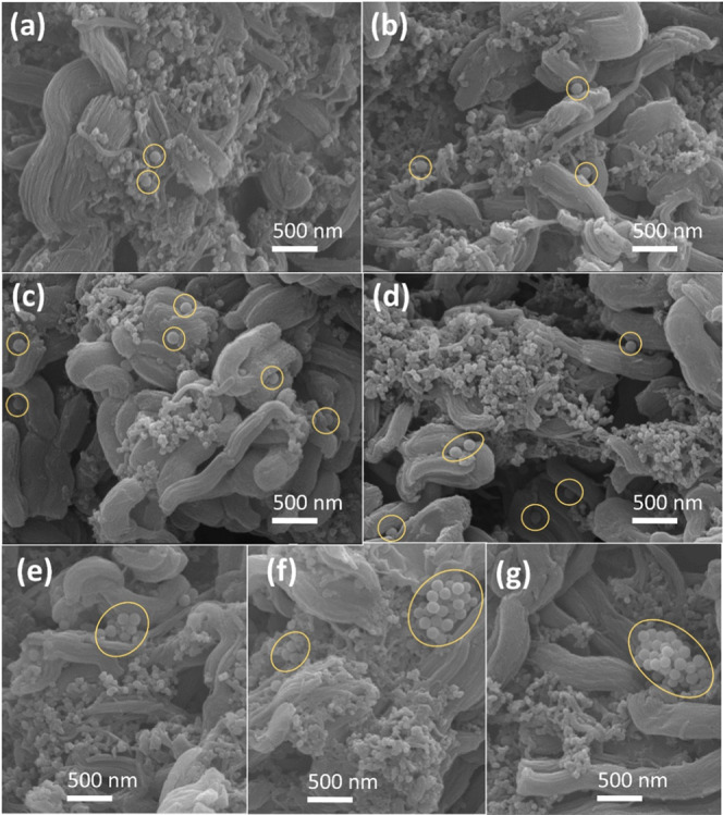
SEM morphologies of the electrode sheets: (a) CS100–1, (b) CS100–2, (c) CS100–4, (d) CS100–6, (e) CS100–8, (f) CS100–10, and (g) CS100–15.
2.2. Effect of SiO2 Mass Fraction on Electrode Hydrophilicity
Figure 2 shows that the water uptake by the CS100–y electrode depended on the SiO2 mass fraction. For the CMK-3 electrode without SiO2 microspheres (CS0), the water uptake was only 18.6%. As the SiO2 mass fraction increased from 1 to 6% (CS100–1 to CS100–6), the water uptake by the electrode increased to 42.1%. This could be attributed to the hydrophilicity of the SiO2 microspheres. However, further increases in the mass fraction of SiO2 (e.g., CS100–8) caused a decrease in water uptake (36.4%), which was attributable to aggregation and the reduced number of hydrophilic regions. Since an aqueous electrolyte was used in this study, water uptake by electrode materials modeled the electrode/electrolyte affinity.
Figure 2.
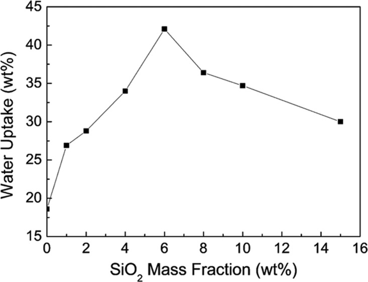
Effects of the SiO2 mass fraction on the electrode water uptake.
2.3. Effect of SiO2 Microsphere Diameter and Mass Fraction on Capacitance
Chronopotentiometry (CP) measurements were used to examine the capacitance of the electrodes containing SiO2 microspheres (50–400 nm; 0–15 wt %). These measurements could improve the understanding of the effect of microspheres on (1) the electrode/electrolyte affinity, (2) the charge transfer, and (3) the capacitance of the supercapacitor. Figure 3a–e demonstrates the impact of SiO2 microspheres (particle sizes 50–400 nm) on the relative capacitance. The charging/discharging curves of the optimal conditions of each group are shown in Figure S9.
Figure 3.
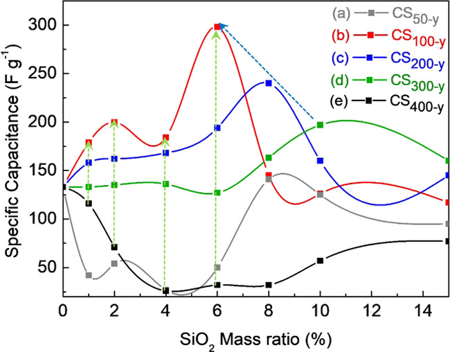
Capacitance versus mass fraction of the SiO2 microspheres with sizes: (a) CS50–y, (b) CS100–y, (c) CS200–y, (d) CS300–y, and (e) CS400–y.
When the mass fractions of the 100 nm SiO2 microspheres were 0, 1, 2, 4, 6, 8, 10, or 15 wt %, the capacitances were 133, 179, 200, 184, 298, 145, 126, and 117 F/g, respectively (Figure 3b). The capacitance increased gradually, peaking at 298 F/g for an S100 content of 6 wt %. This could be attributed to the dispersion of the SiO2 microspheres and thus the enhanced affinity between the electrode and the electrolyte (discussed in Section 2.2); this was confirmed by electrical impedance spectroscopy (EIS; Figure S11a). The Rct (charge transfer resistance) and RΩ (electrode resistance) of CS100–6 were much lower than those of CS0, indicating an improved electrode/electrolyte affinity. Increasing the mass fraction further (from 8 to 15 wt %) caused a decreased capacitance, beginning with the point at which SiO2 microspheres began aggregating (Figure 1e) and limiting the charge conduction.
For SiO2 microspheres with diameters of 200 nm (S200) and 300 nm (S300), a trend similar to that of CS100 was found. The capacitance increased with the mass fraction of SiO2 microspheres and reached maximum values of 240 and 197 F/g at 8 and 10 wt %, respectively (Figure 3c,d). Further increases in the SiO2 content resulted in a decreased capacitance after the SiO2 ratio had reached the point at which aggregation commenced (Figures S4f and S5g). The best capacitance values for CS100–y, CS200–y, and CS300–y occurred at mass fractions just below that at which aggregation occurred, verifying that the aggregation of SiO2 microspheres negatively affected the capacitor performance. Thus, the optimized mass fractions of S100, S200, and S300 were 6, 8, and 10 wt % (CS100–6, CS200–8, and CS300–10), respectively.
When the diameter of the SiO2 microspheres was increased to 400 nm (S400), the addition of the SiO2 microspheres reduced the capacitance below that of CS0 (Figure 3e). No obvious aggregation of the SiO2 microspheres was observed in CS400–y. However, the CS400–y films tended to tilt and peel off after the measurement (Figure S10e–f). In other words, when the particle size of the SiO2 microspheres exceeded a critical point, e.g., 400 nm, reduced adhesion between the electrode film and the substrate led to poor performance and an unstable capacitance (Figure 3e). In contrast, when the size of the SiO2 microspheres was reduced to 50 nm (S50), the extensive agglomeration in all of the CS50–y electrodes (described in Section 2.1 and shown in Figure S3) led to poor penetration of the electrolyte in the electrode. This hindered the local charge transfer, and the capacitance varied independently of the mass fraction of the SiO2 microspheres (Figure 3a).
These results indicated that as the particle size of SiO2 microspheres decreased from 300 to 200 to 100 nm, the optimal mass fraction of SiO2 also decreased from 10 to 8 to 6 wt %, respectively, and the corresponding capacitances were 197, 240, and 298 F/g, respectively (shown as a blue arrow in Figure 3). On the other hand, considering the effect of microsphere size on capacitance, a decrease in the microsphere size led to a higher capacitance when the SiO2 mass fraction ≤6 wt % (shown as green arrows in Figure 3; it should be noted that CS50–y did not follow the trend because of the aggregation discussed in Section 2.1). This could be attributed to the higher surface area affecting the affinity between the electrode and electrolyte. This indicated that the smaller the SiO2 microsphere size, the more effective it was in improving the specific capacitance of the electrode.
2.4. Cycle Stability
The optimized electrode CS100–6 was examined with long-term charge/discharge tests at a current density of 5 A/g. Figure 4 shows the cycle stabilities for CS0 and CS100–6 electrodes, indicating that after 1000 cycles, the capacitance retention of the CS100–6 electrode was 91.5%, much higher than those of CS0 (68.0%), CS200–8 (77.5%; Figure S12), and CS300–10 (79.3%; Figure S12). Other studies report stabilities between 78 and 90% after 1000 cycles,21,27,28 so the composite electrode described herein exhibits excellent performance.
Figure 4.

Cycle life diagram of CS100–6 and CS0 at the current density of 5 A/g.
Degradation during the charge–discharge process is often due to the volume expansion/shrinkage in polymer-based and metal oxide based supercapacitors.33−35 Fan et al. found that the charging/discharging process can also lead to a degradation of the carbon microstructure, resulting in poorer electrochemical and cycling performance.36 Therefore, the low retention rate of the CS0 electrode can be attributed to the reduced utilization of active material caused by rapid charging/discharging cycling. Conversely, with the dispersion of SiO2 microsphere in the CS100–6 electrode, more uniform expansion and shrinkage can be expected to mitigate the microstructure degradation and declining capacitance. The phenomenon can also be observed by comparing the EIS of the CS100–6 electrode before and after 1000 charging/discharging cycling test (shown in Figure S11a,b, respectively). It was found that the Rct was increased after the cycling test, which can be attributed to degradation. The improved cycle stability exhibited by the CS100–6 electrode can be attributed to the uniform penetration of the electrolyte into the electrode, which prevents microscale cracking of the electrode during charge/discharge.
In summary, these results clarified that an effective dispersion of hydrophilic SiO2 allows an electrolyte to permeate an electrode effectively and uniformly, thereby increasing the effective active area for electrochemical reactions, improving charge transport, and improving the cycle stability.
2.5. Energy and Power Densities
To further evaluate the applicability of our proposed electrode, Ragone plots were constructed to compare the energy and power densities of CS0, CS100–6, and recently reported materials. As shown in Figure 5, when the current density in the CS0 electrode was increased from 1 to 10 A/g, the energy density was reduced from 21.05 to 0.16 Wh/kg; when the current density through the CS100–6 electrode was increased from 1 to 10 A/g, its energy density (26.25 Wh/kg) was only reduced to 11.53 Wh/kg. In addition, when the current density was further increased to 20 A/g, the energy densities of CS0 and CS100–6 were 0.07 and 6.67 Wh/kg, respectively. Only when the current density was increased to more than 30 A/g did the energy density of CS100–6 begin to show a significant decrease. Besides, CS100–6 also shows outstanding performance under high power density conditions, when compared with a pristine electrode (CS0). The results indicate that the energy density and high power density can be improved easily by the dispersion of SiO2 microspheres. Figure 5 shows that the performance of our CS100–6 electrode surpasses those described in recent studies.23,26,37−39 Additionally, Ragone plots shown in Figure S13 indicates improved performance resulting from the dispersion of SiO2 microspheres to active carbon, CeO2/CMK-3, graphene, and our recently reported graphene/CNT/MnOv-based electrodes,40 suggesting that the proposed method is compatible for broader electrode materials.
Figure 5.

Comparison between CS0 and CS100–6.
3. Conclusions
This is the first report demonstrating enhanced energy density, power density, and cycling stability realized by improving the electrolyte/electrode affinity and dispersing the SiO2 microspheres in the electrode. Mesoporous carbon CMK-3 was adopted as an EDLC active material, SiO2 microspheres were added to the electrodes, and the effects of the microspheres’ sizes and mass fractions on specific capacitance were studied to optimize electrodes. Further, the electrodes’ energy density vs power density and cycle stability were compared.
When the size of the SiO2 microspheres was reduced (300, 200, and 100 nm), the optimal mass fraction decreased (10, 8, and 6 wt %, respectively) and the capacitance values increased (197, 240, and 298 F/g, respectively), indicating that a smaller particle size leads to larger microsphere surface areas. This facilitates the electrolyte/electrode contact and ion transport. Our CS100–6 electrode exhibited excellent cycle stability and retained 91.53% of its capacitance after 1000 charge–discharge cycles. A comparison via Ragone plots showed that higher energy density and higher power density can be achieved by dispersing SiO2 microspheres in the electrodes. When the CMK-3 electrodes operate under a low-current mode (1 A), the energy densities of CS0 and CS100–6 were 21.05 and 26.05 Wh/kg, respectively; however, when these operated under high current (10 A), the energy densities of CS0 and CS100–6 were 0.16 and 11.5 Wh/kg, respectively. This illustrates the outstanding performance of the CS100–6 electrode, especially under high power density conditions. Finally, it was proved that the proposed method is compatible with a variety of materials; therefore, further integrating this strategy with emerging supercapacitors is valuable for their commercial applications.
4. Experimental Section
4.1. Preparation of Mesoporous Template and CMK-3
Mesoporous silica (SBA-15) was prepared according to the known procedure.18,19,41,42 It was started by dissolving P123 triblock copolymer (EO20-PO70EO20; Pluronic P123; Aldrich) in aqueous hydrochloric acid (1.3 M) at a temperature ≤40 °C. The desired amount of tetraethyl orthosilicate (TEOS, Aldrich) was added, and the solution was stirred for 1 h in a 40 °C water bath. The mixture was aged in an oven at 100 °C for 48 h. The white precipitate was filtered and washed on a Büchner funnel, dried in an oven, and calcined in a furnace at 570 °C for 6 h to obtain the mesoporous SBA-15.
Mesoporous carbon (CMK-3) was made by nanocasting using the mesoporous SBA-15 as a template.18 CMK-3 was prepared by dissolving sucrose in a dilute H2SO4 solution (0.3 M). This solution was slowly mixed with the desired quantity of SBA-15 and heated for 12 h (6 h under 60 °C; 6 h under 120 °C) to effect dehydration. The mixture was subjected to high-temperature carbonization at 900 °C under a nitrogen atmosphere, and the silica template was removed with a hydrofluoric acid solution (1.0 M). The mesoporous CMK-3 carbon was filtered with a Büchner funnel, washed until the washings were neutral, and then dried in an oven.
4.2. Preparation of SiO2 Microsphere and Electrodes
The procedure for the preparation of silica microspheres was modified from the method of Jiang et al.43 The desired ratio of aqueous ammonia (1–20 mL) and TEOS (1–10 mL) was added to a stirred aqueous ethanol solution (ethanol 100 mL; H2O 10–15 mL). The resulting solution was stirred at room temperature for 12 h and then centrifuged (6500 rpm) for 20 min. After repeated washing and centrifugation processes, the white precipitate was dried in an oven. Table 1 lists the designations of the SiO2 microspheres (Sx) and the corresponding experimental parameters.
To fabricate electrodes, slurries were prepared by dissolving Sx, CMK-3, Super-P carbon black, and poly(vinylidene fluoride) (PVDF) in N-methyl-2-pyrrolidone (NMP) using 30 min of stirring and 30 min of ultrasonic vibration. The CMK-3:Super-P:PVDF ratio of 8:1:1 was adopted for EDLCs, and various mass fractions (1–15% compared to CMK-3) of Sx (S50, S100, S200, S300, S400) additives were used. The resulting black slurry was used to prepare the electrodes.
The titanium sheet was used as a substrate and a current collector; it was uniformly coated with the slurry and placed in a vacuum oven at 100 °C for 30 min. These resultant electrodes were denoted as CSx–y (Table 1).
4.3. Characterization Techniques
Scanning electron microscopy (SEM, JSM-7100F), transmission electron microscopy (TEM, JEM-1400), and X-ray diffraction (XRD, Panalytical X’Pert3 Powder) were used to analyze the surface morphology, the crystal structure, and the microstructure of the composite materials, respectively. Energy-dispersive X-ray spectrometry (EDS) was employed to observe the chemical composition and distribution of the electrode components. Porosity and specific surface area were analyzed with 77 K N2 adsorption/desorption isotherm experiments using an accelerated surface area and porosimetry analyzer (ASAP-2020). The affinity of the electrode material to the electrolyte was evaluated using hygroscopicity; the electrode material was dried in an oven and then placed in a container with 90% relative humidity at room temperature for 24 h. The dry weight (Wdry) and moist weight (Wwet) were compared, and water uptake was calculated using eq 1.
| 1 |
Chronopotentiometry (CP) experiments (potentiostat CHI 6273E) were used to measure the specific capacitance and its retention in long-term operations. Platinum wire counter electrodes, Ag/AgCl reference electrodes, and 1 M sulfuric acid electrolyte solution were employed to measure the half-cell potentials with the working electrodes described above. Equation 2 was used to calculate the capacitance. The normalized result, i.e., specific capacitance (F/g), was used for evaluating the performance. This examination was done with various current densities (1–50 A/g), and Ragone plots were drawn on logarithmic scales to illustrate the power density vs energy density curves
| 2 |
Acknowledgments
This work was financially supported by the Ministry of Science and Technology (MOST), Taiwan (grant number MOST 107-2221-E-167-019 and 108-2221-E-167-009-MY3). Authors also thank the Green Energy and Engineering Materials Research Center, National Chin-Yi University of Technology (NCUT) for their assistance on the BET, XRD, and SEM–EDS measurements.
Supporting Information Available
The Supporting Information is available free of charge at https://pubs.acs.org/doi/10.1021/acsomega.0c00669.
SEM, TEM, and EDS mapping images of the specimens; XRD pattern of mesoporous materials; charge/discharge curves and photographs of electrodes; EIS Nyquist plot and equivalent circuit; cyclic life diagram of electrodes; and Ragone plots of various electrodes (PDF)
The authors declare no competing financial interest.
Supplementary Material
References
- Poonam S.; Sharma K.; Arora A.; Tripathi S. K. Review of supercapacitors: Materials and devices. J. Energy Storage 2019, 21, 801–825. 10.1016/j.est.2019.01.010. [DOI] [Google Scholar]
- Kandalkar S. G.; Dhawale D. S.; Kim C.-K.; Lokhande C. D. Chemical synthesis of cobalt oxide thin film electrode for supercapacitor application. Synth. Met. 2010, 160, 1299–1302. 10.1016/j.synthmet.2010.04.003. [DOI] [Google Scholar]
- Dong J.; Wang Z.; Kang X. The synthesis of graphene/PVDF composite binder and its application in high performance MnO 2 supercapacitors. Colloids Surf., A 2016, 489, 282–288. 10.1016/j.colsurfa.2015.10.060. [DOI] [Google Scholar]
- Qi W.; Li X.; Wu Y.; Zeng H.; Kuang C.; Zhou S.; Huang S.; Yang Z. Flexible electrodes of MnO 2/CNTs composite for enhanced performance on supercapacitors. Surf. Coat. Technol. 2017, 320, 624–629. 10.1016/j.surfcoat.2016.10.038. [DOI] [Google Scholar]
- Zhong C.; Deng Y.; Hu W.; Qiao J.; Zhang L.; Zhang J. A review of electrolyte materials and compositions for electrochemical supercapacitors. Chem. Soc. Rev. 2015, 44, 7484–7539. 10.1039/C5CS00303B. [DOI] [PubMed] [Google Scholar]
- Zhang G.; Xiao X.; Li B.; Gu P.; Xue H.; Pang H. Transition metal oxides with one-dimensional/one-dimensional-analogue nanostructures for advanced supercapacitors. J. Mater. Chem. A 2017, 5, 8155–8186. 10.1039/C7TA02454A. [DOI] [Google Scholar]
- Xiao X.; Zou L.; Pang H.; Xu Q. Synthesis of micro/nanoscaled metal–organic frameworks and their direct electrochemical applications. Chem. Soc. Rev. 2020, 49, 301–331. 10.1039/C7CS00614D. [DOI] [PubMed] [Google Scholar]
- Cheng Y.; Xiao X.; Pan K.; Pang H. Development and application of self-healing materials in smart batteries and supercapacitors. Chem. Eng. J. 2020, 380, 122565 10.1016/j.cej.2019.122565. [DOI] [Google Scholar]
- Aradilla D.; Sadki S.; Bidan G. Beyond conventional supercapacitors: Hierarchically conducting polymer-coated 3D nanostructures for integrated on-chip micro-supercapacitors employing ionic liquid electrolytes. Synth. Met. 2019, 247, 131–143. 10.1016/j.synthmet.2018.11.022. [DOI] [Google Scholar]
- Wang P.; Zhou H.; Meng C.; Wang Z.; Akhtar K.; Yuan A. Cyanometallic framework-derived hierarchical Co3O4-NiO/graphene foam as high-performance binder-free electrodes for supercapacitors. Chem. Eng. J. 2019, 369, 57–63. 10.1016/j.cej.2019.03.080. [DOI] [Google Scholar]
- Yang Q.; Liu Y.; Yan M.; Lei Y.; Shi W. MOF-derived hierarchical nanosheet arrays constructed by interconnected NiCo-alloy@NiCo-sulfide core-shell nanoparticles for high-performance asymmetric supercapacitors. Chem. Eng. J. 2019, 370, 666–676. 10.1016/j.cej.2019.03.239. [DOI] [Google Scholar]
- Osti N. C.; Gallegos A.; Dyatkin B.; Wu J.; Gogotsi Y.; Mamontov E. Mixed Ionic Liquid Improves Electrolyte Dynamics in Supercapacitors. J. Phys. Chem. C 2018, 122, 10476–10481. 10.1021/acs.jpcc.8b02521. [DOI] [Google Scholar]
- Jeyaranjan A.; Sakthivel T. S.; Neal C. J.; Seal S. Scalable ternary hierarchical microspheres composed of PANI/rGO/CeO2 for high performance supercapacitor applications. Carbon 2019, 151, 192–202. 10.1016/j.carbon.2019.05.043. [DOI] [Google Scholar]
- Miller E. E.; Hua Y.; Tezel F. H. Materials for energy storage: Review of electrode materials and methods of increasing capacitance for supercapacitors. J. Energy Storage 2018, 20, 30–40. 10.1016/j.est.2018.08.009. [DOI] [Google Scholar]
- Cherusseri J.; Sambath Kumar K.; Choudhary N.; Nagaiah N.; Jung Y.; Roy T.; Thomas J. Novel mesoporous electrode materials for symmetric, asymmetric and hybrid supercapacitors. Nanotechnology 2019, 30, 202001 10.1088/1361-6528/ab0685. [DOI] [PubMed] [Google Scholar]
- Zhang M.; Wang G.; Lu L.; Wang T.; Xu H.; Yu C.; Li H.; Tian W. Improving the electrochemical performances of active carbon-based supercapacitors through the combination of introducing functional groups and using redox additive electrolyte. J. Saudi Chem. Soc. 2018, 22, 908–918. 10.1016/j.jscs.2018.02.001. [DOI] [Google Scholar]
- Cherusseri J.; Sambath Kumar K.; Pandey D.; Barrios E.; Thomas J. Vertically Aligned Graphene–Carbon Fiber Hybrid Electrodes with Superlong Cycling Stability for Flexible Supercapacitors. Small 2019, 15, 1902606 10.1002/smll.201902606. [DOI] [PubMed] [Google Scholar]
- Phan T. N.; Gong M. K.; Thangavel R.; Lee Y. S.; Ko C. H. Enhanced electrochemical performance for EDLC using ordered mesoporous carbons (CMK-3 and CMK-8): Role of mesopores and mesopore structures. J. Alloys Compd. 2019, 780, 90–97. 10.1016/j.jallcom.2018.11.348. [DOI] [Google Scholar]
- Lo A.-Y.; Jheng Y.; Huang T.-C.; Tseng C.-M. Study on RuO2/CMK-3/CNTs composites for high power and high energy density supercapacitor. Appl. Energy 2015, 153, 15–21. 10.1016/j.apenergy.2015.04.050. [DOI] [Google Scholar]
- Vinu A.; Miyahara M.; Mori T.; Ariga K. Carbon nanocage: a large-pore cage-type mesoporous carbon material as an adsorbent for biomolecules. J. Porous Mater. 2006, 13, 379–383. 10.1007/s10934-006-8034-1. [DOI] [Google Scholar]
- Ali G. A. M.; Fouad O. A.; Makhlouf S. A.; Yusoff M. M.; Chong K. F. Co3O4/SiO2 nanocomposites for supercapacitor application. J. Solid State Electrochem. 2014, 18, 2505–2512. 10.1007/s10008-014-2510-3. [DOI] [Google Scholar]
- Iro Z. S.; Subramani C.; Kesavan T.; Dash S. S.; Sasidharan M.; Sundramoorthy A. K. MnO2 nanorods/SiO2 sphere coated on single-wall carbon nanotubes as supercapacitor electrode for high energy storage applications. Mater. Res. Express 2017, 4, 124004 10.1088/2053-1591/aa9e12. [DOI] [Google Scholar]
- Lei Z.; Zhang J.; Zhao X. S. Ultrathin MnO2 nanofibers grown on graphitic carbon spheres as high-performance asymmetric supercapacitor electrodes. J. Mater. Chem. 2012, 22, 153–160. 10.1039/C1JM13872C. [DOI] [Google Scholar]
- Davoodabadi A.; Li J.; Liang Y.; Wood D. L.; Singler T. J.; Jin C. Analysis of electrolyte imbibition through lithium-ion battery electrodes. J. Power Sources 2019, 424, 193–203. 10.1016/j.jpowsour.2019.03.115. [DOI] [Google Scholar]
- Lo A.-Y.; Huang C.-Y.; Sung L.-Y.; Louh R.-F. Low Humidifying Proton Exchange Membrane Fuel Cells with Enhanced Power and Pt–C–h-SiO2 Anodes Prepared by Electrophoretic Deposition. ACS Sustainable Chem. Eng. 2016, 4, 1303–1310. 10.1021/acssuschemeng.5b01264. [DOI] [Google Scholar]
- Zhang Y.; Zhao Y.; Cao S.; Yin Z.; Cheng L.; Wu L. Design and Synthesis of Hierarchical SiO2@C/TiO2 Hollow Spheres for High-Performance Supercapacitors. ACS Appl. Mater. Interfaces 2017, 9, 29982–29991. 10.1021/acsami.7b08776. [DOI] [PubMed] [Google Scholar]
- Zhang Z. Q. MnO2 Density - Dependent Supercapacitive Characteristics of SiO2/MnO2 Core-shell Nanostructure. Int. J. Electrochem. Sci. 2016, 6138–6148. 10.20964/2016.07.54. [DOI] [Google Scholar]
- Zheng J. H.; Zhang R. M.; Cheng K. K.; Liu T.; Xu Z. Q.; Wang X. G.; Yu P. F. SiO2 nanospheres assembled on MoS2 nanosheets for improving electrochemical performance for supercapacitors. J. Mater. Sci.: Mater. Electron. 2019, 30, 14405–14413. 10.1007/s10854-019-01809-9. [DOI] [Google Scholar]
- Wang H.; Liu R.; Yang C.; Hao Q.; Wang X.; Gong K.; Wu J.; Hu Y.; Li Z.; Jiang J. Smart and designable graphene–SiO2 nanocomposites with multifunctional applications in silicone elastomers and polyaniline supercapacitors. RSC Adv. 2017, 7, 11478–11490. 10.1039/C7RA00262A. [DOI] [Google Scholar]
- Leonard K. C.; Suyama W. E.; Anderson M. A. Improvement of electrochemical capacitor electrodes using SiO2 nanoparticles. Electrochim. Acta 2011, 56, 10137–10144. 10.1016/j.electacta.2011.08.116. [DOI] [Google Scholar]
- Li J.; Lin Y.; Zhao B. Spontaneous Agglomeration of Silver Nanoparticles Deposited on Carbon Film Surface. J. Nanopart. Res. 2002, 4, 345–349. 10.1023/A:1021120723498. [DOI] [Google Scholar]
- Loosli F.; Vitorazi L.; Berret J.-F.; Stoll S. Towards a better understanding on agglomeration mechanisms and thermodynamic properties of TiO2 nanoparticles interacting with natural organic matter. Water Res. 2015, 80, 139–148. 10.1016/j.watres.2015.05.009. [DOI] [PubMed] [Google Scholar]
- Hao S.; Sun Y.; Liu Y.; Zhang Y.; Hu G. Facile synthesis of porous SnO2 film grown on Ni foam applied for high-performance supercapacitors. J. Alloys Compd. 2016, 689, 587–592. 10.1016/j.jallcom.2016.07.278. [DOI] [Google Scholar]
- Sun Z.; Zhang J.; Ye F.; Wang W.; Wang G.; Zhang Z.; Li S.; Zhou Y.; Cai J. Vulcanization treatment: An effective way to improve the electrochemical cycle stability of polyaniline in supercapacitors. J. Power Sources 2019, 443, 227246 10.1016/j.jpowsour.2019.227246. [DOI] [Google Scholar]
- Khosrozadeh A.; Singh G.; Wang Q.; Luo G.; Xing M. Supercapacitor with extraordinary cycling stability and high rate from nano-architectured polyaniline/graphene on Janus nanofibrous film with shape memory. J. Mater. Chem. A 2018, 6, 21064–21077. 10.1039/C8TA07426G. [DOI] [Google Scholar]
- Fan W.; Xia Y.-Y.; Tjiu W. W.; Pallathadka P. K.; He C.; Liu T. Nitrogen-doped graphene hollow nanospheres as novel electrode materials for supercapacitor applications. J. Power Sources 2013, 243, 973–981. 10.1016/j.jpowsour.2013.05.184. [DOI] [Google Scholar]
- Niu L.; Li Z.; Hong W.; Sun J.; Wang Z.; Ma L.; Wang J.; Yang S. Pyrolytic synthesis of boron-doped graphene and its application as electrode material for supercapacitors. Electrochim. Acta 2013, 108, 666–673. 10.1016/j.electacta.2013.07.025. [DOI] [Google Scholar]
- Raymundo-Piñero E.; Cadek M.; Wachtler M.; Beguin F. Carbon nanotubes as nanotexturing agents for high power supercapacitors based on seaweed carbons. ChemSusChem 2011, 4, 943–949. 10.1002/cssc.201000376. [DOI] [PubMed] [Google Scholar]
- Ding R.; Qi L.; Jia M.; Wang H. Facile and large-scale chemical synthesis of highly porous secondary submicron/micron-sized NiCo2O4 materials for high-performance aqueous hybrid AC-NiCo2O4 electrochemical capacitors. Electrochim. Acta 2013, 107, 494–502. 10.1016/j.electacta.2013.05.114. [DOI] [Google Scholar]
- Lo A.-Y.; Saravanan L.; Tseng C.-M.; Wang F.-K.; Huang J.-T. Effect of Composition Ratios on the Performance of Graphene/Carbon Nanotube/Manganese Oxide Composites toward Supercapacitor Applications. ACS Omega 2020, 5, 578–587. 10.1021/acsomega.9b03163. [DOI] [PMC free article] [PubMed] [Google Scholar]
- TamilSelvan S.; Aldeyab S. S.; Zaidi J. S. M.; Arivuoli D.; Ariga K.; Mori T.; Vinu A. Preparation and characterization of highly ordered mesoporous SiC nanoparticles with rod shaped morphology and tunable pore diameters. J. Mater. Chem. 2011, 21, 8792–8799. 10.1039/c1jm10545k. [DOI] [Google Scholar]
- Lakhi K. S.; Singh G.; Kim S.; Baskar A. V.; Joseph S.; Yang J.-H.; Ilbeygi H.; Ruban S. J. M.; Vu V. T. H.; Vinu A. Mesoporous Cu-SBA-15 with highly ordered porous structure and its excellent CO2 adsorption capacity. Microporous Mesoporous Mater. 2018, 267, 134–141. 10.1016/j.micromeso.2018.03.024. [DOI] [Google Scholar]
- Jiang X.; Tang X.; Tang L.; Zhang B.; Mao H. Synthesis and formation mechanism of amorphous silica particles via sol–gel process with tetraethylorthosilicate. Ceram. Int. 2019, 45, 7673–7680. 10.1016/j.ceramint.2019.01.067. [DOI] [Google Scholar]
Associated Data
This section collects any data citations, data availability statements, or supplementary materials included in this article.