Abstract
Cell sickling is the process in which intracellular polymerization of deoxygenated sickle hemoglobin (HbS) leads to distorted, rigid cells, resulting in abnormal blood rheology and painful vaso-occlusion. Current methods for detection of this process mainly rely on optical microscopy of cellular morphology and measurements of cell deformability and blood rheology. As electrical impedance of cells is a sensitive indicator of changes in cellular structure and biophysical characteristics, it can be a promising marker for characterization of abnormal blood rheology and a means more convenient than optics to be integrated into point-of-care devices. In this work, a microfluidics-based electrical impedance sensor has been developed for characterizing the dynamic cell sickling–unsickling processes in sickle blood. The sensor is capable of measuring the continuous variation in the sickle cell suspension due to cyclic hypoxia-induced intracellular HbS polymerization and depolymerization. Simultaneous microscopic imaging of cell morphological change shows the reliability and repeatability of the electrical impedance-based measurements of cell sickling and unsickling processes. Strong correlation is found between the electrical impedance measurement and patients’ hematological parameters such as levels of HbS and fetal hemoglobin. The combination of electrical impedance measurement and on-chip hypoxia control provides a promising method for rapid assessment of the dynamic processes of cell sickling and unsickling in patients with sickle cell disease.
Keywords: sickle cell disease, cell sickling, electrical impedance, microfluidics, cyclic hypoxia, biomarker, biosensor
Graphical Abstract:
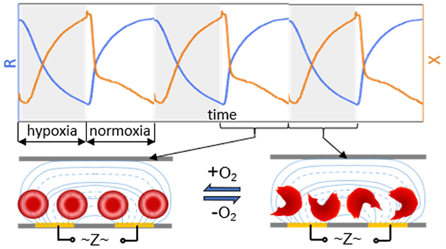
Sickle cell disease (SCD) is a common, inherited hematological disorder in which the life expectancy of the affected individuals can be significantly shortened.1,2 SCD is caused by the mutation on the hemoglobin beta gene (Glu6Val, βS) that results in an abnormal oxygen-carrying protein, sickle hemoglobin (HbS).3 At low oxygen conditions, HbS polymerizes into fibers, causing cell sickling, which is reflected by cell shape change and increased cell stiffness. The sickled cells tend to stick together in small blood vessels, leading to vaso-occlusion and consequent acute and chronic clinical complications.4 The competition between the delay time of cell sickling and the time for a cell traversing through a narrow capillary bed is associated with the onset of vaso-occlusion.5 Parameters such as local oxygen tension, the concentration of HbS, and concentration of fetal hemoglobin (HbF) directly determine the rate of cell sickling.6 Resuming oxygen tension can break down HbS fibers and recover cell shape.3 During blood circulation, sickle cells experience repeated sickling–unsickling processes as they traverse through different parts of the body.7 Morphological changes associated with repeated cell sickling events may lead to permanent cell damage due to cell membrane loss or distortion,8 and the formation of irreversibly sickled cells which is poorly deformable9 and of short life span.10 Thus, the evaluation of the dynamic processes of sickling and unsickling is important in the prediction of the cellular behavior in circulation and assessment of clinical severity of the disease.
Most studies of cell sickling and unsickling are based on the microscopic observations of morphological change in sickle cells exposed to oxygenated and deoxygenated conditions using optical microscope.11–14 Quantitation of cell morphology is usually conducted offline, which can be time-consuming, considering the extreme heterogeneity in SCD. As a delay exists between the processes of intracellular HbS polymerization/depolymerization and the cell morphological change observable by optical microscopy,15 the stand-alone morphology analysis does not offer the capability to capture the change in the intracellular content as well as a real-time monitoring of the dynamic cellular behavior in response to transient change in oxygen conditions. Probing of the kinetics of the HbS polymerization and depolymerization is typically based on free hemoglobin from erythrocyte lysates.16–19 Therefore, a technical gap exists for a real-time measurement of the morphological and intracellular changes during cell sickling and unsickling processes simultaneously.
Electrical impedance spectroscopy is useful that can be used either as a stand-alone or in combination with optical microscopy. Electrical impedance has been widely utilized to characterize cellular changes in cell cultures such as cell spreading,20 multiplication,21 differentiation,22 cell response to chemical compounds,23 as well as in single bioparticle evaluation such as cell type,24,25 deformability,26–28 disease status,29,30 dielectric properties,31,32 and the growth of a single microtissue spheroids.33 Since the conductive cytoplasm of animal cell is encapsulated by capacitive cell membrane, whether the electrical current can penetrate the cell membrane or remains in the extracellular compartment depends on the applied frequency.34 At low frequencies, current is blocked by the cell membrane and mostly pass through the extracellular compartment. In this case, changes in cell morphology can be revealed by the electrical impedance since the amount of current blocked by the cell relies on the cell shape and size. At high frequencies, the cell membrane is charged and discharged faster; current penetrates cell membrane so that the changes in intracellular compartment can be revealed by the electrical impedance. Thus, a multifrequency electrical impedance signal can be used to probe changes in both extra- and intracellular compartments simultaneously. In addition, electrical impedance measurement is naturally quantitative in real time, and offers convenience in direct or indirect contact with the samples of interest, allowing integrations to microfluidics platform and optical microscopy.
In this paper, we report a new microfluidic sensor development that is capable of measuring the continuous variation in a cell suspension in response to a cyclic hypoxia challenge, mimicking the variation in in vivo oxygen tension in blood circulation. We further characterize the rate of cell sickling and percentage of sickled cells, which are important contributing factors of abnormal blood rheology and sickle cell vaso-occlusion. In addition, we establish the correlations between the in vitro measurements and the patients’ hematological parameters. This shows a potential clinical relevance because it serves as a proof-of-concept of electrical impedance as a label-free, biophysical marker of cell sickling events as well as a sensitive tool for probing the dynamic cellular and subcellular processes beyond the optical microscopy. The developed electrical impedance sensor may be potentially used for assessing vaso-occlusion risk, disease severity, and therapeutic treatment in SCD.
EXPERIMENTAL SECTION
Sample Preparation.
Five blood samples (ss1, ss2, ss3, ss4, and ss5) from individuals with SCD were collected following Institutional Review Board (IRB) approvals from Florida Atlantic University and the University of Miami. A normal blood sample (aa) was obtained from a local blood bank and used as a control in this study. All samples were stored at 4 °C and tested within 2 weeks of collection. Blood samples were washed twice with phosphate-buffered saline (PBS) at the speed of 2000 rpm at room temperature for 2 min. The hematocrit of each tested sample was 0.6% by resuspending 6 μL red blood cell pellet into 1 mL PBS.
Microfluidic Chip for Impedance Measurement.
The microfluidic chip consists of a PDMS double-layer microchannel and interdigitated electrode array (IEA) that is printed on a glass substrate (Figure 1). The upper gas channel is 1500 μm wide and 75 μm deep and the lower cell channel is 500 μm wide and 150 μm deep. A 150-μm-thick PDMS film is used to separate the gas channel from the cell channel, allowing gas molecules to permeate through easily but preventing cells from drying out. Four openings, with 1.5-mm diameters, are created, allowing separate gas and medium exchanges using standard 0.02 in. ID/0.06 in. OD microbore tubing. The IEA consists of 16 pairs of fingers with 20 μm bands and 20 μm gaps. Each finger has a 100-nm-thick Au layer atop a 10-nm-thick Ti layer that are deposited on the 700-μm-thick glass substrate using E-beam vaporization and patterned by standard photolithography techniques. The PDMS microchannel was obtained by casting a microfabricated SU-8/Si master with a degassed PDMS mixture (10:1 of base to agent ratio) and curing under 70 °C for 2 h. A permanent bonding was accomplished between the microchannel and the IEA chip by air plasma treatment. Two-inch-long, 22-gauge copper-based wires were soldered to the IEA pads and connected to the impedance spectroscope. The cell channel was washed with 70% ethanol followed by deionized (DI) water, then primed with PBS. The cell suspension was then injected gently into the liquid channel of the device using a 1 mL syringe. Cells were allowed to sediment to the bottom of the channel before impedance measurement was performed.
Figure 1.
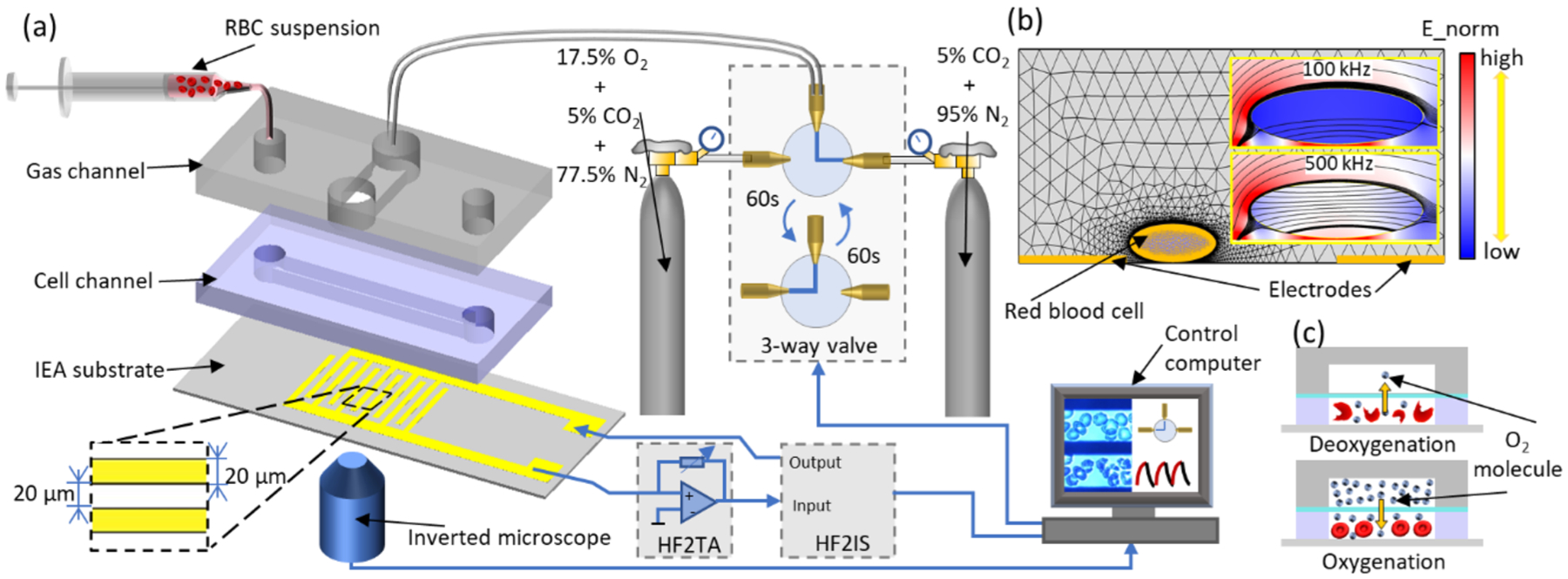
Schematic diagram showing the impedance measurement system with cyclic hypoxia control in microfluidic environment: (a) Exploding view of the microfluidics-based impedance sensor and the key components for cyclic hypoxia control and impedance measurement; (b) Finite element analysis of current flow in the impedance sensor by COMSOL Multiphysics; (c) Schematic diagram of a cross-section of the microfluidic device for oxygen control and induced cell sickling and unsickling.
Cyclic Hypoxia Control.
Oxygen concentration in the cell channel was controlled by the oxygen concentration in the supplied gas mixture to the gas channel. Cyclic hypoxia was created by switching between an oxygen-rich gas mixture (17.5% oxygen, 5% carbon dioxide with the balance of nitrogen) and an oxygen-poor gas mixture (5% carbon dioxide with the balance of nitrogen) using a programmable 3-way valve (LabSmith., CA, USA) (Figure 1). The programmable 3-way valve was switched between the oxygen-rich mixture and the oxygen-poor mixture at a time interval of 60 s. The cyclic hypoxia lasted for 8 min in each testing. To verify the effectiveness of the gas control from the gas channel and calibration of the oxygen concentration in the cell channel, a fluorescence dye, tris (2,20-bipyridyl dichlororuthenium) hexahydrate (Ru(bpy)) (Sigma-Aldrich) was used. Its fluorescence intensity is inversely proportional to the dissolved oxygen concentration.35 The cell channel was filled with DI water containing Ru(bpy). Gray values (red curve) converted from the fluorescence intensity of Ru(bpy) were plotted as a function of time (Figure 2). The corresponding oxygen concentration in the gas channel (blue curve) was shown as a reference. The delay in the transition from one oxygen concentration level to the other in the cell channel (gray value) was diffusion limited, depending on the thickness of PDMS film. The current setting resulted in a hypoxia (O2% near zero) duration of approximately 44.5 s and a normoxia (O2% near 17.5%) duration of about 42.5 s.
Figure 2.
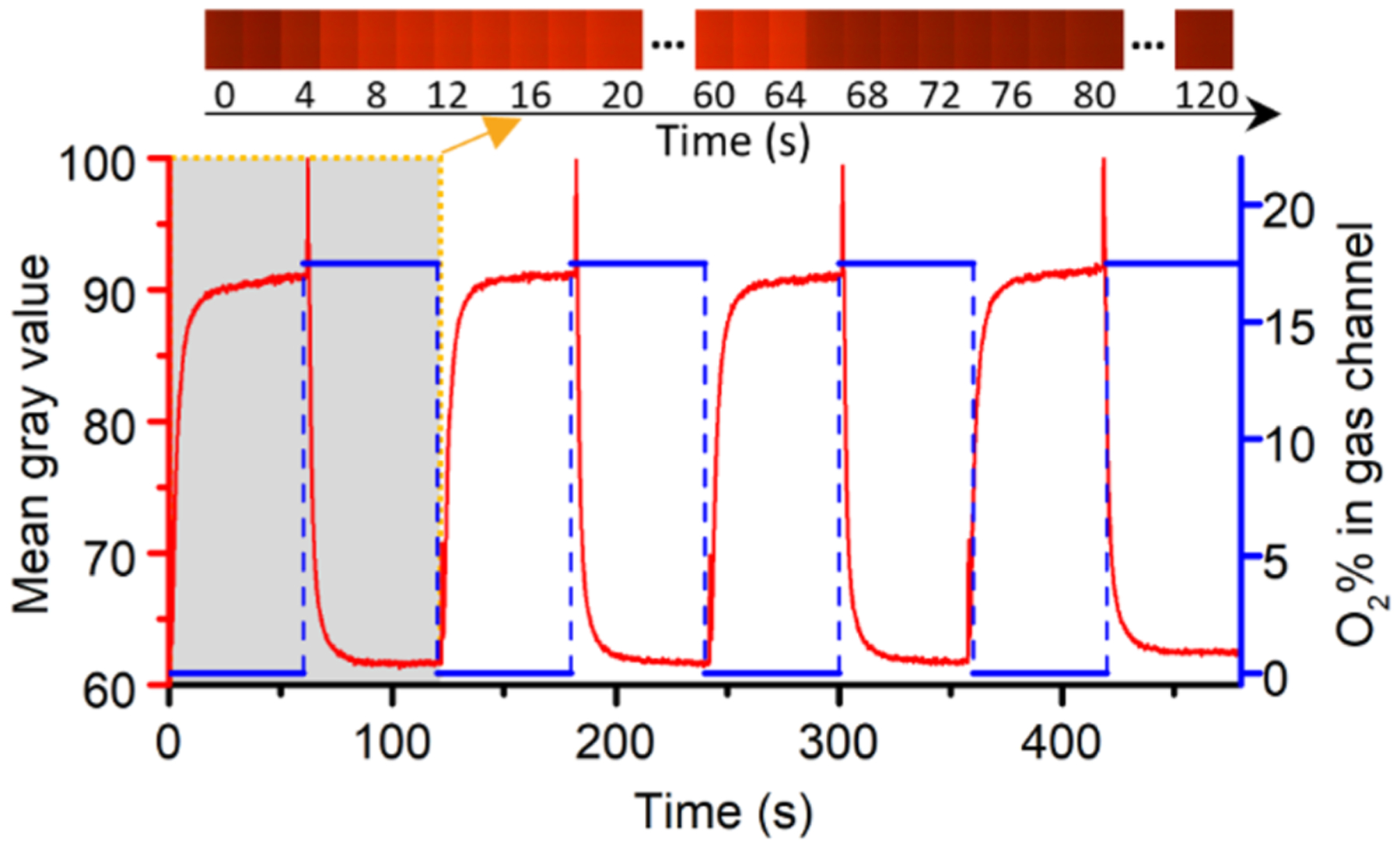
Characterization of the oxygen tension in the cell channel by the oxygen sensitive dye in response to the gas supply in the gas channel. The color bar is a combination of fluorescence images at representative moments during the first hypoxia-normoxia cycle (indicated by the shaded area).
Electrical Impedance Measurement.
Electrical impedance measurements were taken at 100 kHz and 500 kHz, which provided favorable conditions for the measurements of both cellular membrane and interior with current setup, as well as to avoid the adverse effects from electrolysis at lower frequencies or parasitic inductance effects at higher frequencies. Feasibility of the selected frequencies was verified by numerical simulation of the electrical field magnitude and electric current streamlines in the testing zone using COMSOL Multiphysics 5.2 (COMSOL, Inc., Burlington, MA). The numerical model consisted of a pair of IEA fingers where a cell suspending in the proximity, similar to that described in a previous publication.36 As shown in the Figure 1b, at 100 kHz, near-cell current streamlines are blocked by the capacitive cell membrane and take their paths through the medium, suggesting that the impedance signal will be dominated by the shape and size of the cell; at 500 kHz, most near-cell current streamlines pass through cell membrane and the electric field strength of cell interior increases, suggesting the role of intracellular material in the impedance signal increases. In the experiments, sinusoidal voltages of 100 mVpk at frequencies of 100 kHz and 500 kHz were applied simultaneously to the IEA chip. The collected electrical current signals were converted to voltage signals using a current amplifier (HF2TA, Zurich Instrument, AG, Switzerland) and then fed back to the impedance spectroscope (HF2IS, Zurich Instrument, AG, Switzerland). A sampling rate of 57 points of data per second was used to capture the variations in the cell suspension in response to gas exchange through the valve. This allows a measurement, in real time, for the electrical impedance of the cell suspension. The raw data recorded by the impedance spectroscope was in the format of complex current, and it was converted into complex impedance based on Ohm’s Law.29 To remove the effect of residuals between the instrument calibration plane and the specimen under test, the calculated impedance value was corrected by the standard open/ short/load compensation method.37
Cell Morphology Analysis.
The IEA chip contains electrode-free viewing strips to facilitate observation using an inverted microscope (Olympus IX-81, Olympus America, PA, USA). Microscopic videos were recorded through a digital camera (The imaging Source, NC, USA) simultaneously with the impedance measurement. Cell morphological change, quantified by the overall area blocked by the cells in the viewing strips, was analyzed from the time lapse video using ImageJ.38 For each specimen, the relative cell area was normalized to that of the initial frame, and averaged between 6 and 10 microscopy views. Cell morphological change was then mapped to the impedance data of the cell suspension for each individual sample in time domain. The percentage of cells that exhibited characteristics of morphological sickling upon hypoxia was defined as sickled fraction, following a previous publication.13 The sickled fraction of each sample was expressed as mean ± SD, averaged from 8 microscopy views.
RESULTS AND DISCUSSION
Electrical Impedance as a Marker of Cell Sickling and Unsickling Events.
The measurement starts from normoxia and the changes of both components of the impedance signals, resistance, R, and reactance, X, relative to the start points R0 and X0 were calculated separately for each blood sample
| (1) |
| (2) |
Figure 3 shows the calculated data at both measured frequencies. Both resistance and reactance parts have high sensitivities in response to variations in the oxygen level in the cell channel. They follow closely the profile of the oxygen level. When the valve shifts its position for gas exchange, it exerts a dynamic load to the cell suspension, which can be identified by a small brief peak in the recorded impedance signal. Subtle variations in the impedance signals were observed for medium without cells (m, black curves) and normal cell suspension (aa, pink curves) in response to cyclic hypoxia treatment, indicating the content of dissolved oxygen does not lead to a detectable signal as being due to the cell sickling–unsickling events by electrical impedance. Remarkable changes in electrical impedance were observed in all the sickle cell samples during the hypoxia-normoxia cycles. In response to deoxygenation, electrical resistance of sickle cell suspension decreases, and reactance increases. In response to reoxygenation, the two measures change oppositely. At 500 kHz, the resistance is slightly noisier than that of 100 kHz. As frequency increases, more current passes through the cell membrane into the cell interior. Each sickle cell sample showed a slightly different response among the consecutive hypoxia–normoxia cycles.
Figure 3.
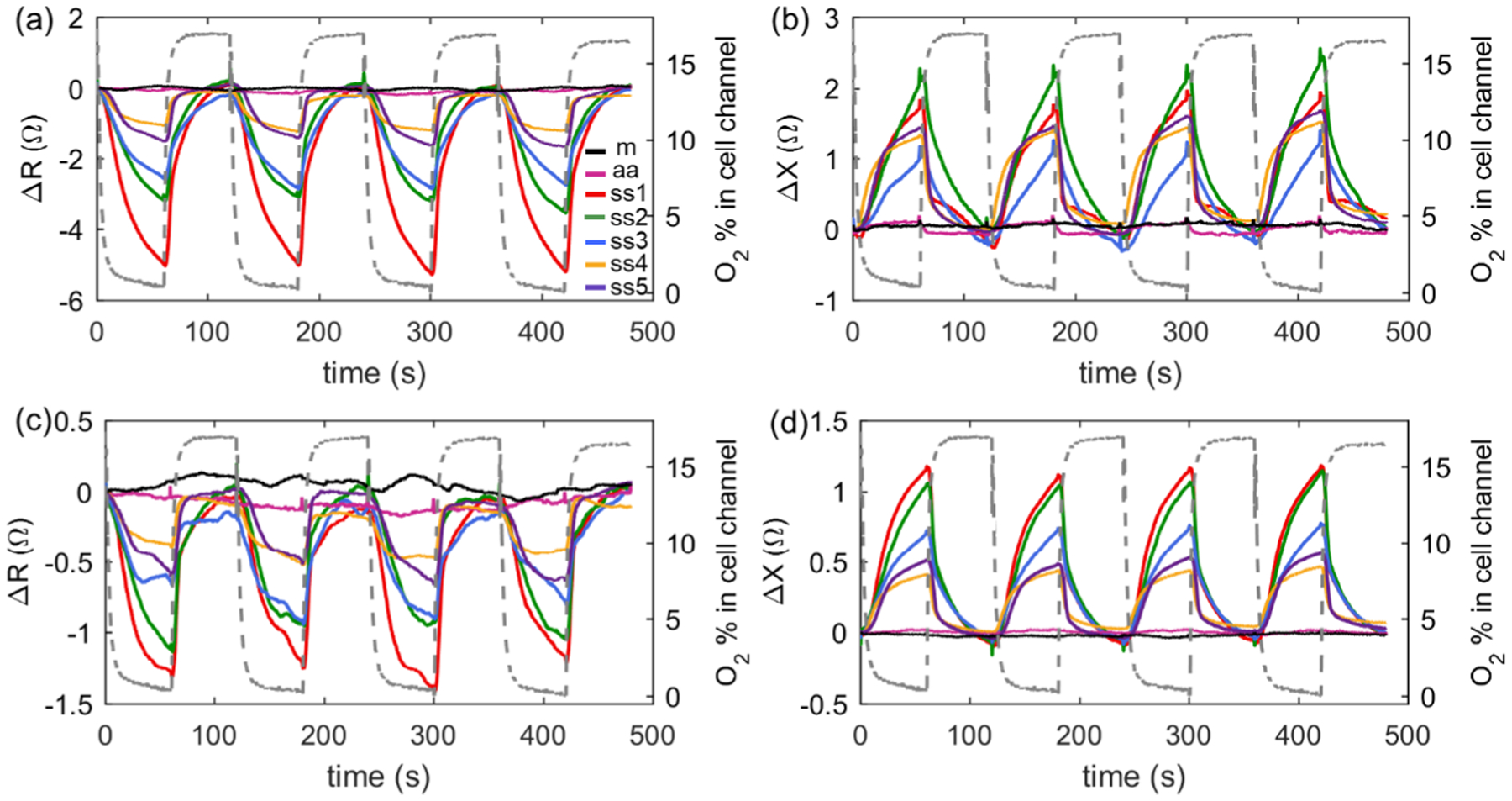
Absolute impedance changes measured in the four hypoxia–normoxia cycles: (a) resistance at 100 kHz, (b) reactance at 100 kHz, (c) resistance at 500 kHz, and (d) reactance at 500 kHz. Gray-dashed lines indicate oxygen concentration in cell channel. (b–d) share the same legend with (a). m, medium only; aa, normal blood sample; and ss1–ss5, five sickle blood samples.
The relative change in the impedance of cell suspension between normoxia and hypoxia was quantified separately during each cycle, by calculating the relative difference between the resistance Rr or reactance Xr values at the two transition points where the valve switched between hypoxia and normoxia (Figure 4a)
| (3) |
| (4) |
The subscripts “hypo” and “norm” denote hypoxia and normoxia, respectively. This resulted in four pairs of data for each sample at a specific frequency. The cycle-averaged values of resistance/reactance relative changes for the normal red blood sample are negligible at 100 kHz with 0.04%/0.08% and at 500 kHz with 0.025%/0.044%. The corresponding values of the cycle-averaged impedance relative change for ss1 are greatest with changes of 3.61%/0.71% at 100 kHz and 1.10%/1.85% at 500 kHz. These values are more than 1 order of magnitude higher than those of sample aa at both frequencies.
Figure 4.
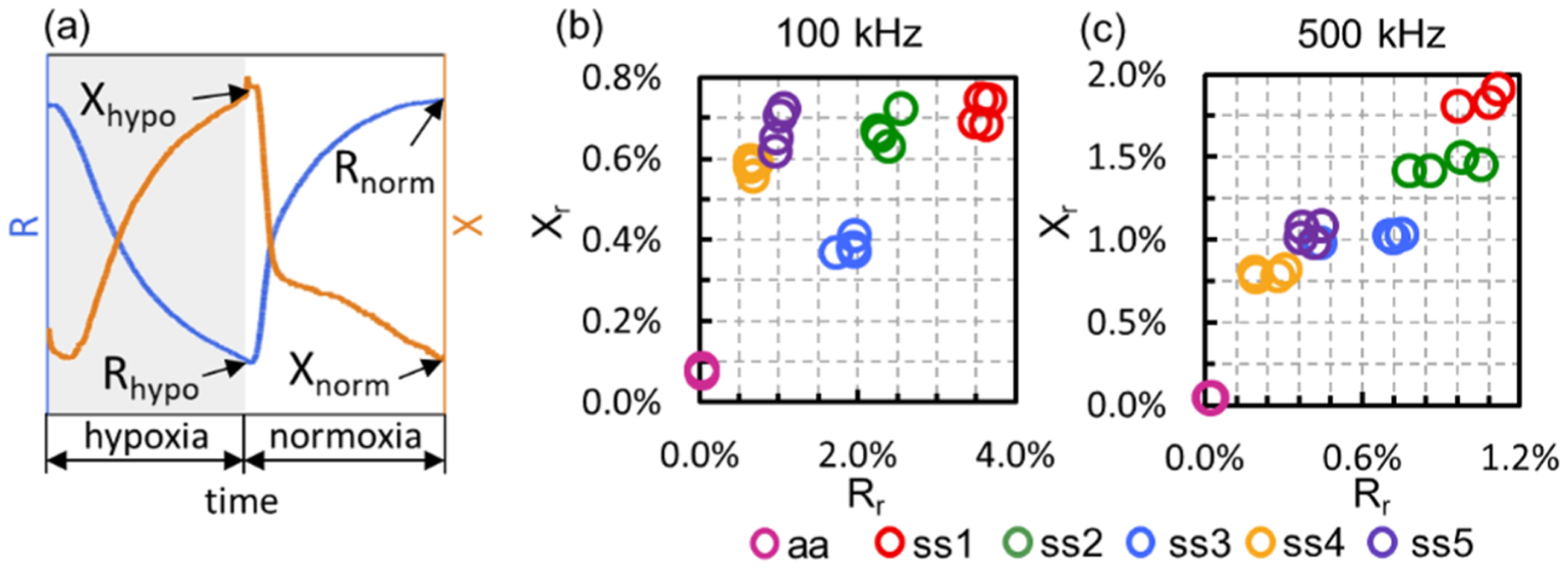
(a) Representative curves of impedance variation during hypoxic and normoxic conditions. Scatter plot of reactance relative change versus resistance relative change for samples aa and ss1–ss5 at the tested frequencies of (b) 100 kHz and (c) 500 kHz.
Significant variation exists among the tested sickle blood samples as quantified by the relative changes in the magnitudes of Rr and Xr. Both intersample and intercycle variations can be observed (Figure 4). Even though the intercyclic variations are obvious at both frequencies, all the tested samples can be successfully differentiated with a minimum overlap using a combination of Rr and Xr at both frequencies. Permanent cell damage due to exposure to electrical field39 and repeated sickling–unsickling process8 was not observed during the four cycles (8 min in total). This allowed us to probe the processes of HbS polymerization–depolymerization and the consequent shape change using impedance without complications from other factors. The intercycle variations can be detected by the relative reactance Xr at 100 kHz and the relative resistance Rr at 500 kHz. Such variation may be caused by the uncertainty in the orientation and structure of the formed HbS fibers40 in each hypoxia session, delay time in the HbS polymerization–depolymerization, as well as the associated variations in cell shapes. The intersample variations among the five sickle cell samples showed a consistent trend in Rr between the two frequencies, as ss1 > ss2 > ss3 > ss5 > ss4, while no such trend was identified in Xr. This suggests that the relative resistance is a more robust assessment for intersample variations than the relative reactance, regardless of the electrical frequency.
Cell Shape Change Associated with Sickling–Unsickling Process.
Both extracellular and intracellular parameters associated with the process of cell sickling can influence the electrical impedance of cell suspension. Under normoxia, the majority of sickle cells exhibited a biconcave disk shape similar to normal cells (Figure 5a). Under hypoxia, sickle cells became darker and the majority of them exhibited obvious shape change, specifically, the sickled friction of each sample is at least 91.6 ± 3.6% (ss3) (Table S-1). The relative cell area, A, corresponding resistance, R, and absolute value of reactance, |X|, were normalized separately for each sickle cell sample
| (5) |
where P stands for A, R, or |X|. Normalized data per sample during the first hypoxia–normoxia cycle were compared at each frequency (Figure 5b, see Figure S-1 for the other three cycles). The gray shading represents the hypoxia session during which cells experience the sickling process and the bright area represents the normoxia session where cells go through the unsickling process. It was observed experimentally that the rate of cell unsickling was higher than the rate of cell sickling. This was reflected in the cell area, which changes slowly in response to deoxygenation but abruptly in response to reoxygenation.
Figure 5.
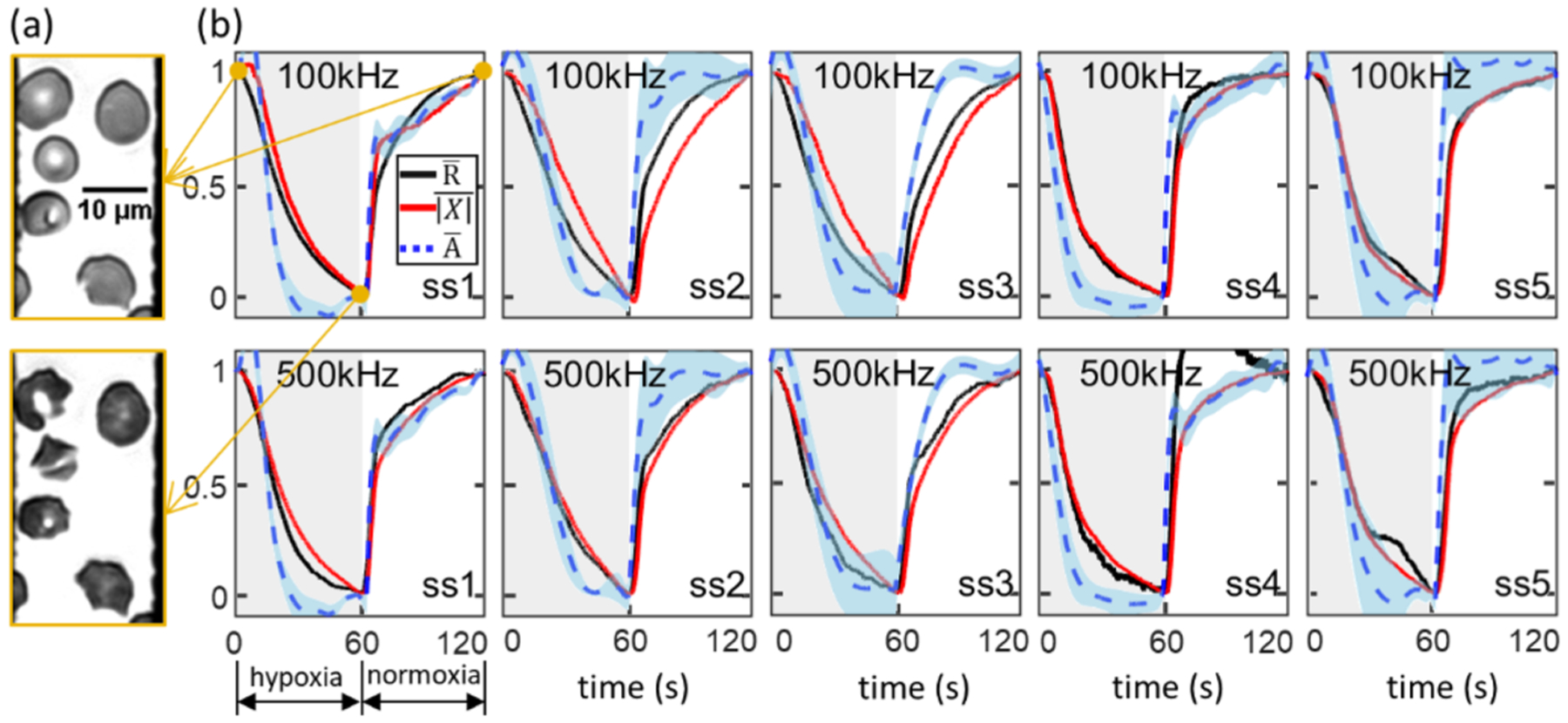
(a) Representative image (ss1) showing a population of cells before (upper panel) and after (bottom panel) hypoxia treatment; (b) normalized values of mean cell area Ā (blue dashed curve) with standard deviation (light blue shading), impedance resistance (black curve) and absolute impedance reactance (red curve) as a function of time within the first hypoxia–normoxia cycle.
There is an obvious delay before the area starts to decrease after the application of hypoxia, especially for ss1, ss2, ss3, and ss5. However, the change of impedance begins almost immediately after the start of hypoxia. Furthermore, cell area decreases quickly compared to the rate of impedance change once it gets started, so that after the impedance change lags far behind the cell area change at both frequencies. This suggests intracellular polymerization begins before and continues after cell morphological sickling. In ss2, ss3, and ss5, recovery of impedance lags far behind the cell area recovery at both frequencies; suggesting the rate of intracellular HbS fiber dissolution is much lower than that of membrane recovery. In contrast, no obvious delays were found in ss1. These findings indicate that the five sickle cell samples in the current study have significantly different kinetics of morphological cell sickling and intracellular polymerization and depolymerization. In addition, there is a delay from resistance to reactance in both the sickling and unsickling processes. This is probably due to the fact that resistance is essentially a friction while reactance is an inertia against the motion of electrons; therefore, resistance reacts faster than reactance.41
Correlation between Electrical Impedance and Hematological Parameters.
Normalized impedance of all the five samples during the first hypoxia session were compared, allowing us to identify intersample variations (Figure 6a; see Figure S-2 for the other three cycles). The difference in sickling behavior is substantial. Both normalized resistance and reactance of ss4 decrease most rapidly within the first 30 s and tend to flatten afterward, while those of ss2 decrease at a relatively lower speed along the deoxygenation process. To quantify these variations, we introduced a new parameter, decreasing rate of resistance ν, which was defined as the inverse of the area under the curve within a hypoxia session using the trapezoidal method
| (6) |
where n is the index of each measured data point. By plotting the value of ν against %HbF, a moderate linear correlation was found slowly decreasing the rate of resistance corresponding to higher concentration of HbF at 500 kHz (Figure 6b2). At 100 kHz (Figure 6b1), the resistance decreases at a lower rate of ν ≈ 0.045 when %HbF is higher than 17.4%, in contrast to the significantly increased rate of ν ≈ 0.059 when %HbF is as low as 14.2%. These correlations agree with the previous report42 that increased levels of HbF retard the polymerization of HbS. Resistance relative change Rr was plotted against the %HbS of individual samples. We noticed that there is a strong linear relationship between Rr and %HbS at both 100 kHz (Figure 6b3) and 500 kHz (Figure 6b4); the sample with higher concentration of HbS showed a greater change in impedance resistance. These results indicate that electrical impedance can potentially be used as a supplementary detection method for hematological assay in SCD. HbS% and HbF% are important parameters used clinically for assessment of disease severity6 and SCD associated complications,43 which are measured from cell lysate by electrophoresis technique. As electrical impedance is a label-free, sensitive marker of cell sickling and unsickling processes, establishment of its correlations with HbS % and HbF% may offer a new opportunity for rapid and label-free assessment of SCD in conjunction with the clinical measures.
Figure 6.
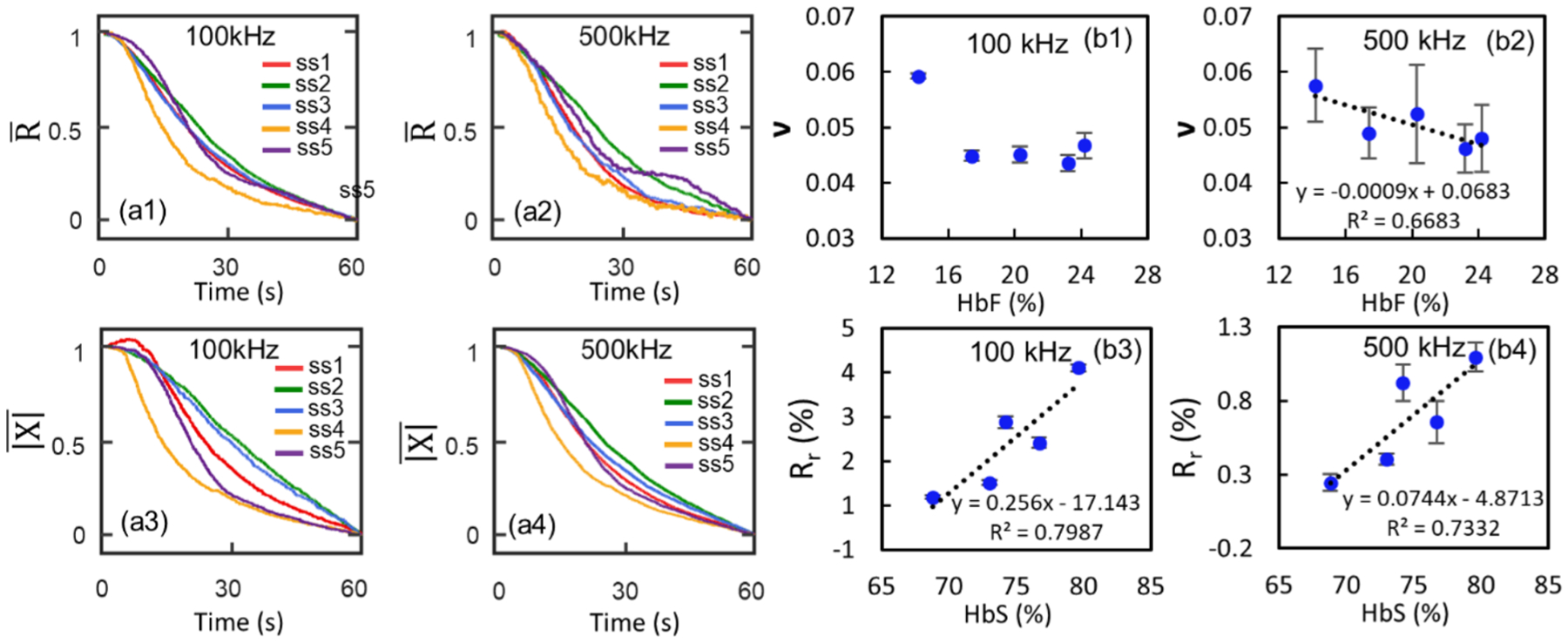
(a) Normalized values of impedance resistance, , and absolute impedance reactance, , as a function of time within the first hypoxia session. (b) Correlation between electrical resistance and hematological parameters: Decreasing rate of resistance, ν at (b1) 100 kHz and (b2) 500 kHz as a function of %HbF. Electrical resistance relative change at (b3) 100 kHz and (b4) 500 kHz as a function of %HbS.
Modeling of Electrical Impedance.
Equivalent circuit modeling was adopted to describe the cell suspension system and identify the contribution of each component to the measured impedance change. In general, an equivalent electrical circuit model analogous to the physical model is utilized to describe the electrical properties of cell suspension, including the electrical double layer as a capacitor, the conductive PBS solution as a resistor, and each individual cell as a series of capacitors and resistors (Figure S-3a). Considering the significant variations in cell size and shape of sickle cells, a simplified circuit model was used to interpolate the overall electrical impedance of cell suspension in response to changes in oxygen tension (Figure S-3b). In this model, all the cells were simplified as an entity consisting of a resistor, Rc, in series with a capacitor, Cc. The surrounding medium was simplified as a single resistor, Rm. Similarly, the electrical double layer from all the IEA fingers has been modeled as a single capacitor, Cedl. Specifically, the total complex impedance of the circuit becomes
| (7) |
Correspondingly, the total resistance and total reactance are
| (8) |
| (9) |
where ω is the angular frequency. Impedance values Rnorm, Xnorm, Rhypo, and Xhypo at 100 kHz and 500 kHz were used to fit the above circuit model.
Three cell suspension parameters, medium resistance, Rm, cell capacitance, Cc, and cell resistance, Rc, that are associated with cell sickling/unsickling processes, as well as electrical double layer capacitance Cedl were listed in Table 1. Values of Rm and Cc decreased, and Rc increased in response to hypoxia for all five samples, suggesting the reasonable accuracy of the equivalent circuit model in the description of sickle cells in suspension. The sickling process of cells yield more space for electrical current going through the conductive medium, resulting in a decreased Rm. Along with the HbS polymerization, individual sickle cells become dehydrated and more solid; thus, the suspended sickle cells become more resistive and less capacitive. These results demonstrated that a multifrequency electrical impedance spectroscopy is useful in measurements of extra- and intracellular compartments during the cell sickling and unsickling processes.
Table 1.
Values of Electric Components of the Established Equivalent Circuit Model
| Rm (Ω) | Cc (nF) | Rc (Ω) | |||||||||||
|---|---|---|---|---|---|---|---|---|---|---|---|---|---|
| normoxia | hypoxia | normoxia | hypoxia | normoxia | hypoxia | ||||||||
| Cedl (nF) | Mean | STDEV | Mean | STDEV | Mean | STDEV | Mean | STDEV | Mean | STDEV | Mean | STDEV | |
| ss1 | 6.9 | 152.7 | 0.1 | 146.7 | 0.2 | 1.60 | 0.004 | 1.50 | 0.007 | 306.2 | 0.8 | 322.0 | 0.8 |
| ss2 | 5.2 | 151.3 | 0.1 | 146.4 | 0.3 | 1.74 | 0.003 | 1.65 | 0.010 | 345.9 | 0.5 | 365.2 | 1.6 |
| ss3 | 5.2 | 148.7 | 0.1 | 145.4 | 0.2 | 1.95 | 0.008 | 1.90 | 0.007 | 322.0 | 1.0 | 333.5 | 0.8 |
| ss4 | 7.1 | 156.7 | 0.1 | 154.2 | 0.1 | 0.99 | 0.002 | 0.88 | 0.005 | 845.1 | 1.2 | 909.2 | 3.4 |
| ss5 | 7.2 | 158.7 | 0.1 | 155.8 | 0.2 | 0.90 | 0.002 | 0.79 | 0.007 | 874.9 | 2.0 | 925.7 | 4.7 |
CONCLUSIONS
In summary, this study demonstrated a microfluidic impedance assay, which is capable of monitoring the dynamic cell sickling and unsickling processes. A series of changes in medium resistance, cell capacitance, and cell resistance that are attributed to intracellular HbS polymerization and depolymerization are recognized to be important contributing factors of the measured electrical impedance variation. Significant correlations between in vitro measurements and clinical hematological parameters were identified. In addition, notable interpatient variations identified from the electrical impedance measurement are consistent with the heterogeneous characteristic of the disease. This assay enabled a label-free means for differentiation between sickle blood and normal blood, as well as detection of cell sickling events in a suspension of cells. With the aid of the automatic gas control, this study provides a proof of concept using electrical impedance as a promising label-free assay of SCD that does not require microscopic imaging or biochemical markers. Further technical developments may focus on a replacement of the gas control unit with oxygen scavenging biochemical reagents, as well as a portable impedance spectroscope to enable a portable, standalone sensor, allowing patient’s self-monitoring of hematological parameters and evaluation of vaso-occlusion risk.
Supplementary Material
ACKNOWLEDGMENTS
The authors thank Ms. Vanessa Cumming at the Division of Pediatric Hematology and Oncology, University of Miami for assistance in acquiring sickle blood samples. This material is based upon work supported by the National Science Foundation under Grant No. 1635312 and No. 1464102.
Footnotes
Supporting Information
The Supporting Information is available free of charge on the ACS Publications website at DOI: 10.1021/acssensors.9b00263.
Summary of results from complete blood count, hemoglobin electrophoresis and the sickled fractions from morphology measurement; normalized values of mean cell area, impedance resistance and absolute impedance reactance as functions of time within the second, third and fourth hypoxia-normxia cycles; normalized impedance resistance and absolute impedance reactance as functions of time within the second, third and fourth hypoxia sessions; electrical impedance modeling of sickle cell suspension. (PDF)
The authors declare no competing financial interest.
REFERENCES
- (1).Platt OS; Brambilla DJ; Rosse WF; Milner PF; Castro O; Steinberg MH; Klug PP Mortality in Sickle-Cell Disease - Life Expectancy and Risk-Factors for Early Death. N. Engl. J. Med 1994, 330 (23), 1639–1644. [DOI] [PubMed] [Google Scholar]
- (2).Haywood C; Lanzkron S Sickle cell disease mortality in the United States: Age at death and contributing causes. Blood 2007, 110 (11), 33a–33a. [Google Scholar]
- (3).Ware RE; de Montalembert M; Tshilolo L. o.; Abboud MR Sickle cell disease. Lancet 2017, 390 (10091), 311–323. [DOI] [PubMed] [Google Scholar]
- (4).Barabino GA; Platt MO; Kaul DK Sickle cell biomechanics. Annu. Rev. Biomed. Eng 2010, 12, 345–367. [DOI] [PubMed] [Google Scholar]
- (5).Eaton WA; Hofrichter J Sickle cell hemoglobin polymerization In Advances in protein chemistry; Elsevier: 1990; Vol. 40, pp 63–279. [DOI] [PubMed] [Google Scholar]
- (6).Kaul D; Nagel R Sickle cell vasoocclusion: many issues and some answers. Experientia 1993, 49 (1), 5–15. [DOI] [PubMed] [Google Scholar]
- (7).Wajih N; Basu S; Jailwala A; Kim HW; Ostrowski D; Perlegas A; Bolden CA; Buechler NL; Gladwin MT; Caudell DL; et al. Potential therapeutic action of nitrite in sickle cell disease. Redox Biol. 2017, 12, 1026–1039. [DOI] [PMC free article] [PubMed] [Google Scholar]
- (8).Padilla F; Bromberg P; Jensen W The sickle-unsickle cycle: a cause of cell fragmentation leading to permanently deformed cells. Blood 1973, 41 (5), 653–660. [PubMed] [Google Scholar]
- (9).Clark MR; Mohandas N; Shohet SB Deformability of oxygenated irreversibly sickled cells. J. Clin. Invest 1980, 65 (1), 189–196. [DOI] [PMC free article] [PubMed] [Google Scholar]
- (10).Goodman S The irreversibly sickled cell: a perspective. Cellular and molecular biology (Noisy-le-Grand, France) 2004, 50 (1), 53–58. [PubMed] [Google Scholar]
- (11).Dufu K; Lehrer-Graiwer J; Ramos E; Oksenberg D GBT440 inhibits sickling of sickle cell trait blood under in vitro conditions mimicking strenuous exercise. Hematol. Rep 2016, 8 (3), 37–41. [DOI] [PMC free article] [PubMed] [Google Scholar]
- (12).Li Q; Henry ER; Hofrichter J; Smith JF; Cellmer T; Dunkelberger EB; Metaferia BB; Jones-Straehle S; Boutom S; Christoph GW; et al. Kinetic assay shows that increasing red cell volume could be a treatment for sickle cell disease. Proc. Natl. Acad. Sci. U. S. A 2017, 114 (5), E689–E696. [DOI] [PMC free article] [PubMed] [Google Scholar]
- (13).Du E; Diez-Silva M; Kato GJ; Dao M; Suresh S Kinetics of sickle cell biorheology and implications for painful vasoocclusive crisis. Proc. Natl. Acad. Sci. U. S. A 2015, 112 (5), 1422–1427. [DOI] [PMC free article] [PubMed] [Google Scholar]
- (14).Van Beers EJ; Samsel L; Mendelsohn L; Saiyed R; Fertrin KY; Brantner CA; Daniels MP; Nichols J; McCoy JP; Kato GJ Imaging flow cytometry for automated detection of hypoxia-induced erythrocyte shape change in sickle cell disease. Am. J. Hematol 2014, 89 (6), 598–603. [DOI] [PMC free article] [PubMed] [Google Scholar]
- (15).Galkin O; Pan W; Filobelo L; Hirsch RE; Nagel RL; Vekilov PG Two-step mechanism of homogeneous nucleation of sickle cell hemoglobin polymers. Biophys. J 2007, 93 (3), 902–913. [DOI] [PMC free article] [PubMed] [Google Scholar]
- (16).Eaton WA; Hofrichter J; Ross PD Delay time of gelation: a possible determinant of clinical severity in sickle cell disease. Blood 1976, 47 (4), 621–627. [PubMed] [Google Scholar]
- (17).Hofrichter J; Ross PD; Eaton WA Kinetics and mechanism of deoxyhemoglobin S gelation: a new approach to understanding sickle cell disease. Proc. Natl. Acad. Sci. U. S. A 1974, 71 (12), 4864–4868. [DOI] [PMC free article] [PubMed] [Google Scholar]
- (18).Moffat K; Gibson QH The rates of polymerization and depolymerization of sickle cell hemoglobin. Biochem. Biophys. Res. Commun 1974, 61 (1), 237–242. [DOI] [PubMed] [Google Scholar]
- (19).Christoph GW; Hofrichter J; Eaton WA Understanding the shape of sickled red cells. Biophys. J 2005, 88 (2), 1371–1376. [DOI] [PMC free article] [PubMed] [Google Scholar]
- (20).Wegener J; Keese CR; Giaever I Electric cell–substrate impedance sensing (ECIS) as a noninvasive means to monitor the kinetics of cell spreading to artificial surfaces. Exp. Cell Res 2000, 259 (1), 158–166. [DOI] [PubMed] [Google Scholar]
- (21).Richards J; Jason A; Hobbs G; Gibson D; Christie R Electronic measurement of bacterial growth. J. Phys. E: Sci. Instrum 1978, 11 (6), 560. [DOI] [PubMed] [Google Scholar]
- (22).Bagnaninchi PO; Drummond N Real-time label-free monitoring of adipose-derived stem cell differentiation with electric cell-substrate impedance sensing. Proc. Natl. Acad. Sci. U. S. A 2011, 108 (16), 6462–6467. [DOI] [PMC free article] [PubMed] [Google Scholar]
- (23).Parviz M; Toshniwal P; Viola HM; Hool LC; Fear PMW; Wood FM; Gaus K; Iyer KS; Gooding JJ Real-time bioimpedance sensing of antifibrotic drug action in primary human cells. ACS sensors 2017, 2 (10), 1482–1490. [DOI] [PubMed] [Google Scholar]
- (24).Chien J-C; Ameri A; Yeh E-C; Killilea AN; Anwar M; Niknejad AM A high-throughput flow cytometry-on-a-CMOS platform for single-cell dielectric spectroscopy at microwave frequencies. Lab Chip 2018, 18 (14), 2065–2076. [DOI] [PubMed] [Google Scholar]
- (25).Gawad S; Schild L; Renaud P Micromachined impedance spectroscopy flow cytometer for cell analysis and particle sizing. Lab Chip 2001, 1 (1), 76–82. [DOI] [PubMed] [Google Scholar]
- (26).Adamo A; Sharei A; Adamo L; Lee B; Mao S; Jensen KF Microfluidics-based assessment of cell deformability. Anal. Chem 2012, 84 (15), 6438–6443. [DOI] [PMC free article] [PubMed] [Google Scholar]
- (27).Zheng Y; Nguyen J; Wang C; Sun Y Electrical measurement of red blood cell deformability on a microfluidic device. Lab Chip 2013, 13 (16), 3275–3283. [DOI] [PubMed] [Google Scholar]
- (28).Zhou Y; Yang D; Zhou Y; Khoo BL; Han J; Ai Y Characterizing deformability and electrical impedance of cancer cells in a microfluidic device. Anal. Chem 2018, 90 (1), 912–919. [DOI] [PubMed] [Google Scholar]
- (29).Liu J; Qiang Y; Alvarez O; Du E Electrical impedance microflow cytometry with oxygen control for detection of sickle cells. Sens. Actuators, B 2018, 255, 2392–2398. [DOI] [PMC free article] [PubMed] [Google Scholar]
- (30).Du E; Ha S; Diez-Silva M; Dao M; Suresh S; Chandrakasan AP Electric impedance microflow cytometry for characterization of cell disease states. Lab Chip 2013, 13 (19), 3903–3909. [DOI] [PMC free article] [PubMed] [Google Scholar]
- (31).Ren D; Chui CO Feasibility of Tracking Multiple Single-Cell Properties with Impedance Spectroscopy. ACS sensors 2018, 3 (5), 1005–1015. [DOI] [PubMed] [Google Scholar]
- (32).Gawad S; Cheung K; Seger U; Bertsch A; Renaud P Dielectric spectroscopy in a micromachined flow cytometer: theoretical and practical considerations. Lab Chip 2004, 4 (3), 241–251. [DOI] [PubMed] [Google Scholar]
- (33).Schmid YR; Bürgel SC; Misun PM; Hierlemann A; Frey O Electrical impedance spectroscopy for microtissue spheroid analysis in hanging-drop networks. ACS Sensors 2016, 1 (8), 1028–1035. [DOI] [PMC free article] [PubMed] [Google Scholar]
- (34).Markx GH; Davey CL The dielectric properties of biological cells at radiofrequencies: applications in biotechnology. Enzyme Microb. Technol 1999, 25 (3–5), 161–171. [Google Scholar]
- (35).Chang-Yen DA; Gale BK Integrated optical biochemical sensor fabricated using rapid-prototyping techniques, In Microfluidics, BioMEMS, and Medical Microsystems; International Society for Optics and Photonics: 2003; pp 185–196. [Google Scholar]
- (36).Qiang Y; Liu J; Yang F; Dieujuste D; Du E Modeling erythrocyte electrodeformation in response to amplitude modulated electric waveforms. Sci. Rep 2018, 8 (1), 10224. [DOI] [PMC free article] [PubMed] [Google Scholar]
- (37).Di Noto V; Giffin GA; Vezzu K; Piga M; Lavina S Broadband dielectric spectroscopy: a powerful tool for the determination of charge transfer mechanisms in ion conductors. Solid state proton conductors: properties and applications in fuel cells 2012, 109–183. [Google Scholar]
- (38).Usami S; Chien S; Scholtz PM; Bertles JF Effect of deoxygenation on blood rheology in sickle cell disease. Microvasc. Res 1975, 9 (3), 324–334. [DOI] [PubMed] [Google Scholar]
- (39).Kotnik T; Miklavčič D Theoretical evaluation of the distributed power dissipation in biological cells exposed to electric fields. Bioelectromagnetics 2000, 21 (5), 385–394. [PubMed] [Google Scholar]
- (40).Edelstein SJ; Telford JN; Crepeau RH Structure of fibers of sickle cell hemoglobin. Proc. Natl. Acad. Sci. U. S. A 1973, 70 (4), 1104–1107. [DOI] [PMC free article] [PubMed] [Google Scholar]
- (41).Hughes JM Practical electronics: Components and techniques; O’Reilly Media, Inc.: 2015. [Google Scholar]
- (42).Akinsheye I; Alsultan A; Solovieff N; Ngo D; Baldwin CT; Sebastiani P; Chui DH; Steinberg MH Fetal hemoglobin in sickle cell anemia. Blood 2011, 118 (1), 19–27. [DOI] [PMC free article] [PubMed] [Google Scholar]
- (43).Steinberg MH Predicting clinical severity in sickle cell anaemia. Br. J. Haematol 2005, 129 (4), 465–481. [DOI] [PubMed] [Google Scholar]
Associated Data
This section collects any data citations, data availability statements, or supplementary materials included in this article.


