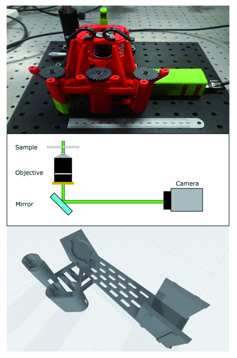
Figure 1. Layout of microscope.
Top - image of microscope as constructed. It is mounted on an aluminium breadboard for portability and stability. The ruler is 15cm and shown for scale. The colours of individual parts are arbitrary. Middle - beam path showing key design parameters. Illumination is from a laser mounted above the sample and the camera is mounted at the primary imaging plane of the microscope objective with an emission filter directly attached. The turning mirror allows a more compact design. Bottom: integrated mirror and camera mount to allow imaging with high sensitivity camera. We used the slots in the base of this part to pass mounting screws to the breadboard for additional stability.

