Abstract
Kidney biopsies are currently performed using preoperative imaging to identify the lesion of interest and intraoperative imaging used to guide the biopsy needle to the tissue of interest. Often, these are not the same modalities forcing the physician to perform a mental cross-modality fusion of the preoperative and intraoperative scans. This limits the accuracy and reproducibility of the biopsy procedure. In this study, we developed an augmented reality system to display holographic representations of lesions superimposed on a phantom. This system allows the integration of preoperative CT scans with intraoperative ultrasound scans to better determine the lesion’s real-time location. An automated deformable registration algorithm was used to increase the accuracy of the holographic lesion locations, and a magnetic tracking system was developed to provide guidance for the biopsy procedure. Our method achieved a targeting accuracy of 2.9 ± 1.5 mm in a renal phantom study.
Keywords: Renal biopsy, kidney cancer, augmented reality, phantom study, image-guided interventions
INTRODUCTION
Cancers of the kidney and renal pelvis constituted over 65,000 new cases and caused over 14,000 deaths in the United States in 20181. Increasingly, to diagnose and better target treatment for these cancers, a renal biopsy is performed. The effectiveness of current diagnostic procedures; however, is often compromised due to poor visualization or inaccurate targeting of the lesion2.
Current diagnosis procedures often use of preoperative computed tomography (CT) scans, which can localize the lesion well and provide good tissue contrast for planning. Ultrasound may also be used which adds the advantage of greater real-time feedback, but lacks the resolution of a CT scan and are inferior at determining the precise lesion location3. Further, CT scans are generally taken in the supine position, whereas the patient lies in the lateral decubitus position during a kidney biopsy. This causes organ deformation and creates a discrepancy between the preoperative and intraoperative scans. While attempting to extract tissue from the lesion, the surgeon must perform a mental cross-modality image fusion, looking between the CT scans and the real-time ultrasound image, and correct for the shifts caused by the different positioning manually. This can cause targeting errors, a factor that has been demonstrated to impair the effectiveness of the procedure, and adds to the risk of a non-diagnostic or false-negative result2, 4.
To alleviate these problems, an augmented reality (AR) system was developed. To aid lesion targeting, holographic lesion representations were displayed in its real-world location based on the segmentation label provided on the preoperative CT scans. The lesion hologram was then transformed based on the intraoperative deformation and movement observed through ultrasound imaging, removing the need for the surgeon to register the images mentally. A magnetic tracker attached to the biopsy needle allowed the program to predict the needle trajectories that would accurately target the lesion, thereby offering potential improvements in diagnostic specificity.
Previous explorations of the utility of AR in renal biopsy have used porcine ureters and kidneys4, whereas this study makes use of custom-molded complex kidney phantoms based on CT scans of a human patient. This study also uses only electromagnetic tracking, as opposed to the combination of electromagnetic, optical, and accelerometer tracking used in prior work.
In this paper, we have designed and developed an AR system to guide a biopsy needle for improved lesion targeting and accuracy. We also designed and developed kidney phantoms to evaluate the AR system performance for lesion targeting.
METHODS
System Overview: Our system is divided into two main portions: preoperative imaging and the intraoperative biopsy procedure. Preoperative imaging is used to generate the 3D scans used for reference during the biopsy procedure. We created a series of kidney phantoms with lesions of interest only visible by CT scan and invisible by ultrasound. We scanned the phantoms using CT imaging and segmented the anatomical features of the phantoms including lesions. Then, before attempting the biopsy procedure, each phantom was scanned again using a two-dimensional (2D), magnetically-tracked ultrasound transducer, and the resultant images used to generate a three-dimensional (3D) ultrasound image of the phantom. The CT scan was then non-rigidly registered to the 3D ultrasound, to compensate for any deformations between the time the scans were taken. This allowed portions of the 3D ultrasound which contained lesions of interest to be identified, despite the ultrasound’s low sensitivity to detect lesions directly.
During the intraoperative biopsy portion, the operator wore an augmented reality headset which displayed holographic representations of the lesions, based on the CT scans taken. The operator used an ultrasound transducer to gather real-time 2D images, which were used to perform additional registrations with the preoperative 3D ultrasound. Since the 3D ultrasound had already been registered with the CT scans, deformations in the 3D ultrasound could be used to determine the current locations of the lesions. This three-step scan process allowed us to avoid the need to perform cross-modality registration between the 2D ultrasound and the 3D CT directly, reducing the computational load and increasing the speed of registration. Magnetic tracking was used to determine locations of the ultrasound transducer and biopsy needle, making it possible to display holographic representations of the ultrasound scans and the trajectory of the needle. Figure 1 depicts the schematic block diagram of the complete system. Each step is described in detail below.
Figure 1.
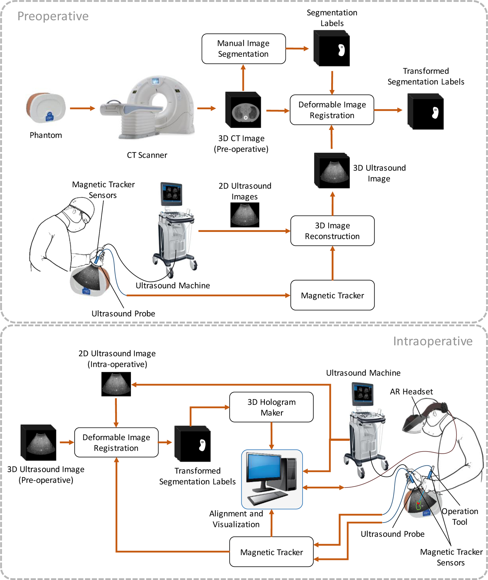
Block diagram of the augmented reality system for renal biopsy, including the preoperative steps (top) and the intraoperative steps (bottom).
2.1. Kidney phantom
We designed a series of kidney phantoms for testing the AR system’s ability to integrate CT and ultrasound imaging and display accurate holograms of lesion locations. To design the phantoms anonymized contrast CT images from a kidney cancer patient were used. The internal structures of the kidney were segmented using 3D Slicer, and the kidney cortex, medulla, and ureter were isolated. The resultant segmentation was exported to stereolithography (STL) files.
Using SolidWorks 2018, the STL files were used to design molds, which were then 3D printed. The phantoms were then fabricated using a 4% agarose gel and assembled with the molds. The structure of the medulla and ureter was 3D printed separately.
2.2. Preoperative
CT scanning and segmentation:
First, we performed CT scans of the phantoms. The lesions on the CT images were manually segmented using 3D Slicer. The segmented lesions were exported as 3D models for later use in the holographic display. Figures 2(A) and 2(B) show the CT images of a sample kidney phantom.
Figure 2.
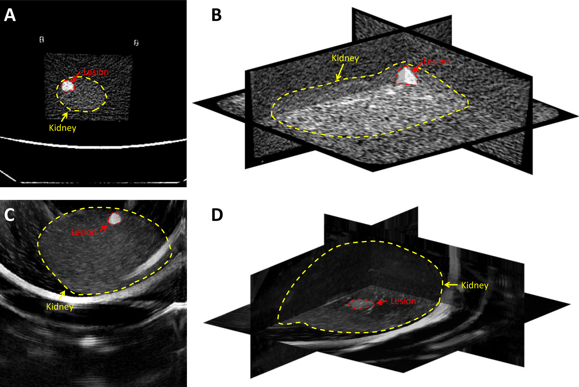
CT and ultrasound imaging of a kidney phantom with visible lesions. A and B: CT images of the phantom, C: One sample 2D ultrasound slice of the kidney phantom, and D: The 3D ultrasound image volume constructed from captured 2D ultrasound images using a tracked transducer. The borders of the kidney and the lesion are displayed with dashed contours.
3D ultrasound image reconstruction:
An ultrasound probe was connected to an Ascension Technologies trakSTAR magnetic tracking system (NDI, Vermont, USA). A program was written to save 2D scan data from the ultrasound device using an Epiphan DVI2USB 3.0 frame grabber (Epiphan, Palo Alto, California, USA), along with the corresponding location and orientation data from the magnetic tracker, at intervals of 0.2 seconds. Then the tracked ultrasound transducer was moved over the surface of the phantom, taking approximately 300 scans in the process. An algorithm was developed to merge the resultant 2D scans and magnetic tracking data to generate a 3D ultrasound image. Figure 2(C) shows a sample 2D ultrasound image and Figure 2(D) shows the 3D ultrasound images of a sample kidney phantom.
Deformable image registration:
The Elastix image toolbox of 3D Slicer was used to perform a non-rigid registration between the 3D ultrasound and the CT scans. We used mutual information6 as the similarity measure and gradient descent optimizer for the image registration. After the two images are registered, the locations of the lesions in the CT scan was mapped to the 3D ultrasound. Here, we considered those specific voxels on the ultrasound image that represented the lesions’ centers and surfaces.
2.3. Intraoperative
Augmented reality (AR) visualization:
For 3D hologram visualization, we used Meta2 augmented reality headset because it could be tethered to a desktop computer and take advantage of the superior processing speed necessary for real-time image registration. Unity was used as the 3D engine to render the holograms, as well as run the magnetic tracking code. The lesion models made from the CT scans were displayed as holograms.
Magnetically tracked ultrasound imaging:
The ultrasound transducer was tracked by a magnetic tracking sensor attached to the probe. Live 2D scans were taken and displayed on the AR headset, superimposed upon the real-world positions that corresponded to the region the ultrasound transducer was imaging. The scans were also transferred to a 3D-to-2D deformable registration algorithm written in MATLAB for aligning the preoperative 3D ultrasound image to the real-time intraoperative 2D ultrasound. The registration method is explained in detail later. The image registration code was executed alongside the main Unity program.
Biopsy:
Another magnetic tracking sensor was also affixed to the biopsy needle gun to track the biopsy needle. This allowed a hologram to be rendered of the predicted needle trajectory, and thus of the region, the needle would extract tissue from, based on the biopsy gun’s current location and orientation. Unity’s collision detection system was used to determine if the predicted tissue extraction location would intersect with the lesion, thus providing feedback on lesion targeting.
Deformable 3D-to-2D ultrasound image registration:
The intraoperative registration tests were performed between intraoperative 3D ultrasounds (moving image) and the live 2D ultrasound image (fixed image) of the phantom in use. The 2D ultrasound image was taken using the frame grabber and saved along with its tracking data at the time of its capture. First, a rigid transformation was applied to the 3D image in MATLAB to roughly align the live 2D ultrasound image to the corresponding cross-section of the 3D image using the tracking information. Then a series of five 2D cross-sectional images extracted from the 3D image around the cross-section defined by the tracker and the deformable Demon registration algorithm7 was used to register each of the five 2D images to the intraoperative ultrasound image. Mean squared error (MSE) values between the fixed and the registered images were calculated. The location and deformation of the registered image with the lowest MSE was considered for fine-tuning the translations of the lesion voxels in the 3D ultrasound, which were previously identified during preoperative image registration. The resultant translation was then applied to the 3D lesion model and used to adjust its position in the augmented reality headset’s holographic representation. Figure 3 shows a holographic rendering, generated with the augmented reality headset, of the lesion model (green), as well as the 2D ultrasound scan.
Figure 3.
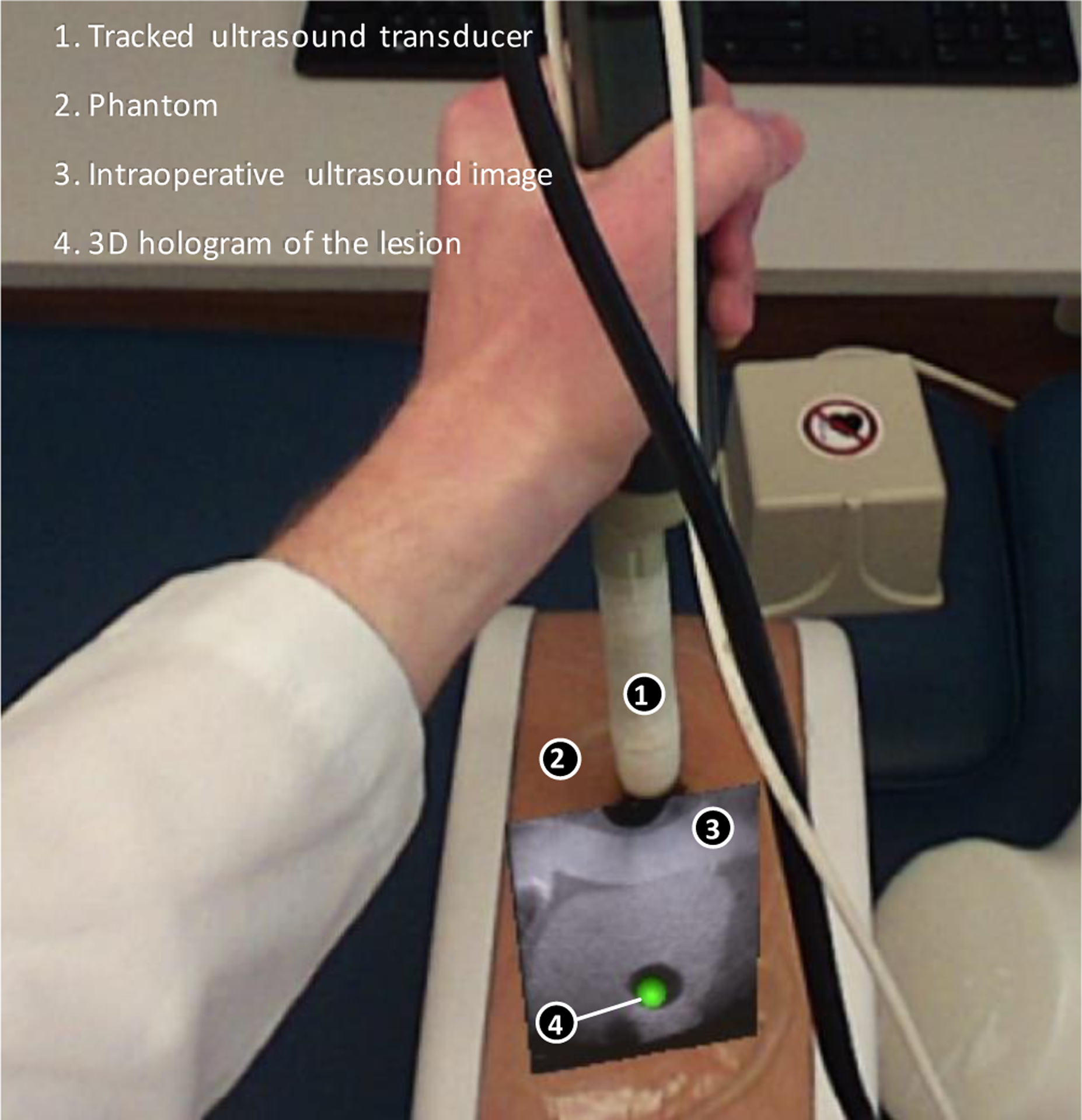
Holographic display of lesion and 2D ultrasound
The intraoperative registration tests were performed between intraoperative 3D ultrasounds and a series of five 2D ultrasounds that were taken using the frame grabber and saved along with their tracking data at the time of their capture. For evaluation, the registration time and target registration error (TRE) were calculated, as well as the MSE between the fixed and the registered image. The MSE between the registered 2D cross-section extracted from the 3D ultrasound image and the 2D intraoperative ultrasound image was calculated using equation (1). For MSEtotal we calculated MSE over all the pixels of and for MSElesion we calculated MSE only for the pixels within the lesion on .
| (1) |
where N is the number of pixels in . is the coordinate of the pixels in 2D space. The TRE the by finding the distance between the lesion center on the registered image and the lesion center on the fixed image.
During the intraoperative registration, an initial rigid registration was performed to align the images using translations, rotations, and scaling. The benefit of this is an increase in computation speed while simultaneously increasing the accuracy of the registration. Registering the images only using deformable registration would make for very lengthy computation time due to the number of iterations the code would need to go through in trying to not only place the images in the same region and general orientation but also try to perform the warping needed to correct for deformations due to patient movement or the biopsy needle. Once the general orientation of the images was corrected, the deformable registration section of the code could then compare the two output images and apply the deformable transformation. In this case, the deformable registration was used to fine-tune the initial rigid registration.
To further increase the computation speed during the deformable registration process, we used the tracking information to estimate the cross-section of the 3D ultrasound from which we are grabbing the live ultrasound frames. We applied the registration to the 2D live ultrasound image and a block of the 3D ultrasound image around the estimated cross-section in a multi-scale scheme. First, the images were downsampled by a factor of eight using the nearest neighbor interpolation. Then the transformation matrix calculated on the scaled images. This resulted in a loss of quality but faster calculation. We then continued the registration in higher scales using downsampling factors of four and two and finalized that in the original scale.
RESULTS
3.1. Intraoperative Registration Results
Table I shows the registration error measured for five different intraoperative ultrasound images. Figure 4 shows the registered image and the fixed image overlaid after both steps of the intraoperative registration. In the second row of the figure, the difference between the fixed and moving images at each stage was illustrated. As shown in the overlay of the original images alongside the overlay of the registered images after both steps of the intraoperative registration in Figure 4, the image used as the fixed image did not match the moving image in the original overlay. After the rigid registration was performed, the position of the lesion in the registered image has translated to match the position of the lesion in the fixed image. After the Demon’s registration, the differences between the registered and fixed images have been minimized, as there is no longer any noticeable difference between the lesions in the overlay. There is still difference observable in the image. This could be because of the interference that occurred during ultrasound imaging, imaging noise and artifacts, tissue deformation during imaging, and the registration error.
Table I.
Intraoperative 3D-to-2D ultrasound image registration results. MSEtotal and MSElesion are the mean squared error over the whole image and only at the lesion region, respectively.
| Test number | Registration Time | MSEtotal | MSElesion | TRE (mm) |
|---|---|---|---|---|
| 1 | 0.65 s | 286 | 49 | 0.31 |
| 2 | 0.67 s | 289 | 63 | 0.25 |
| 3 | 0.64 s | 273 | 63 | 0.26 |
| 4 | 0.74 s | 1071 | 108 | 0.61 |
| 5 | 0.66 s | 3609 | 226 | 6.24 |
| Average | 0.67 s | 1106 | 102 | 1.53 |
Figure 4.
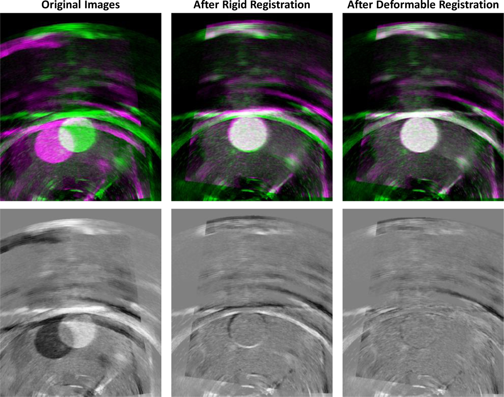
(top) Fixed and moving images overlaid, respectively, in green and magenta before registration, after rigid registration, and after Demon’s registration; (bottom) Difference between the fixed and moving images at each stage.
The total average recorded registration time using an unoptimized implementation of the registration code in MATLAB platform was under 0.7 second.
3.2. Biopsy
Three agar phantoms were created, each one containing lesions visible under both ultrasound and CT scanning, but obscured from intraoperative visual observation by an opaque black layer of agar on the phantom’s top. The phantoms were scanned using preoperative ultrasound and CT, and 3D models were generated based on these scans. Then, a researcher wore the augmented reality headset and used the AR biopsy system displaying the holographic images of the lesions (Figure 5).
Figure 5.
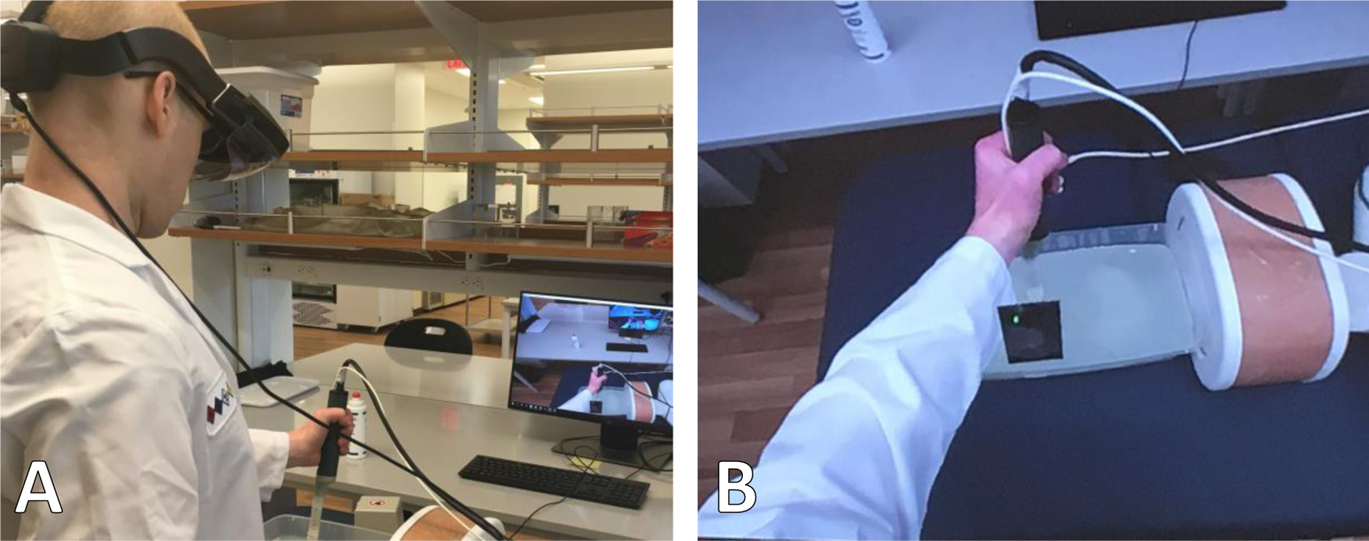
Augmented reality system for biopsy in phantoms. A: The AR biopsy system. B: The holographic view of the AR headset.
A magnetically tracked syringe, used in place of a biopsy needle, was loaded with colored dye and was inserted into the lesions, based on the augmented reality system’s holograms of their positions. Then, the phantoms were dissected. Each needle insertion left a colored dye trail. The endpoint of the trail was used to record the point of needle insertion, and the distance between the trail endpoint and the center of the targeted lesion was measured as the targeting error, as shown in Figure 6.
Figure 6.
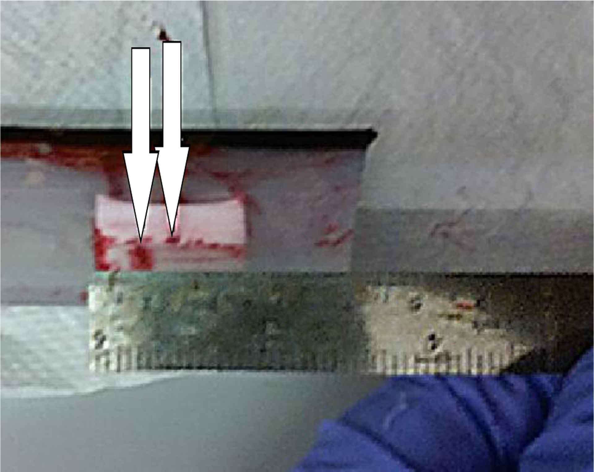
Dissected testing phantom with endpoints of needle insertions marked.
We calibrated the system on two phantoms and tested the AR biopsy system on the third one. The test phantom has seven lesions in different sizes from 4 to 20 mm. We repeated the biopsy 13 times and measured the distance between the tip of the needle and the center of the lesion as the error value. The average (standard deviation) targeting error was 2.9 mm (1.5 mm). Table II shows the error for each of the 13 tests.
Table II.
Targeting accuracy testing results
| Test Number | Targeting Error (mm) | Test Number | Targeting Error (mm) |
|---|---|---|---|
| 1 | 1.0 | 8 | 2.0 |
| 2 | 4.0 | 9 | 6.0 |
| 3 | 2.5 | 10 | 2.5 |
| 4 | 1.5 | 11 | 2.0 |
| 5 | 2.0 | 12 | 5.0 |
| 6 | 2.0 | 13 | 2.5 |
| 7 | 4.5 | Average | 2.9 ± 1.5 |
DISCUSSION AND CONCLUSIONS
In this work, we designed and developed an augmented reality system for renal biopsy. In the proposed approach, we registered a preoperative CT image segmented by an expert to the intraoperative ultrasound images to locate the tumor position. We superimposed the 3D virtual hologram of the kidney lesion on to the real world through an AR headset to assist the clinician in guiding the biopsy needle to the target. The AR system requires only electromagnetic tracking, as opposed to a combination of electromagnetic, optical, and accelerometer tracking, as appeared in prior work4. We used the magnetic tracker to track the ultrasound probe location and orientation.
The proposed AR setup is accurate in guiding the biopsy needle during kidney biopsy in phantoms. It incorporates in-house dual-modality complex kidney phantoms compatible with CT and ultrasound imaging for the accuracy tests. Under AR guidance, we achieved a targeting accuracy of less than 3 mm on kidney phantoms.
The multiscale deformable image registration approach was helpful for fast and accurate localization and targeting the lesions. We used the tracked ultrasound probe to acquire a 3D preoperative ultrasound image. This ultrasound image works as a link between the 3D preoperative CT and 2D intraoperative ultrasound images. This indirect image registration approach between the preoperative CT image and intraoperative 2D ultrasound images made the registration faster and more accurate.
Using this AR system could be beneficial for reducing the number of intraoperative CT imaging usually acquired during the standard renal biopsy procedure, which means less ionizing radiation and shorter procedure time.
4.1. Limitations
Some limitations of this study need to be considered. First, the currently available AR headsets have limited accuracy in environment understanding. Therefore, the overlaid holograms are usually not stable. This is one of the main source of the registration error in our system. We partially addressed this issue by calibrating the system before each experiment and incorporating magnetic tracking information, however, further improvement of the performance is required for an accurate and robust AR visualization. Second, the magnetic field of the tracker is limited to the operation environment. Therefore, by moving the ultrasound probe or the biopsy needle out of the field, the AR system lose the tracking information. In addition, the magnetic tracking accuracy is sensitive to the distortion in the magnetic field caused by metallic objects. It could be addressed by incorporating an optical tracking. Third, the image registration was not optimized and it was implemented on a research platform. For a smooth and real-time image registration, an optimized implementation of the image registration method must be considered.
4.2. Conclusions
We designed an augmented reality system for biopsy needle guidance during renal biopsy and tested the system on in-house phantoms. The system visualized the 3D hologram of the lesion and live ultrasound images overlaid on real-world images through an AR headset. Before the biopsy, we acquire a 3D ultrasound of the kidney using a magnetically tracked ultrasound probe to use that as an intermediary image for mapping the lesion segmentation labels from 3D preoperative CT to 2D intraoperative ultrasound. We presented a multiscale deformable image registration for fast alignment of lesion location on intraoperative ultrasound. The system was found to be sufficiently accurate to target lesions with a radius of less than 3 mm, subject to the limitations of the augmented reality headset’s own display. In future work, the biopsy accuracy could be improved by transferring the system to a headset with a superior tracking system or adding an external optical tracking system; the registration code could also be streamlined for better real-time usability in an operative setting.
ACKNOWLEDGMENTS
This research was supported in part by the U.S. National Institutes of Health (NIH) grants (R01CA156775, R01CA204254, R01HL140325, and R21CA231911) and by the Cancer Prevention and Research Institute of Texas (CPRIT) grant RP190588.
REFERENCES
- [1].Siegel RL, Miller KD, and Jemal A, “Cancer statistics, 2018,” CA Cancer J Clin, 68(1), 7–30 (2018). [DOI] [PubMed] [Google Scholar]
- [2].Londoño DC, Wuerstle MC, Thomas AA, Salazar LE, Hsu J-WY, Danial T, and Chien GW, “Accuracy and implications of percutaneous renal biopsy in the management of renal masses,” The Permanente Journal, 17(3), 4 (2013). [DOI] [PMC free article] [PubMed] [Google Scholar]
- [3].Uppot RN, Harisinghani MG, and Gervais DA, “Imaging-guided percutaneous renal biopsy: rationale and approach,” American Journal of Roentgenology, 194(6), 1443–1449 (2010). [DOI] [PubMed] [Google Scholar]
- [4].Patel HD, Johnson MH, Pierorazio PM, Sozio SM, Sharma R, Iyoha E, Bass EB, and Allaf ME, “Diagnostic accuracy and risks of biopsy in the diagnosis of a renal mass suspicious for localized renal cell carcinoma: systematic review of the literature,” The Journal of urology, 195(5), 1340–1347 (2016). [DOI] [PMC free article] [PubMed] [Google Scholar]
- [5].Maes F, Collignon A, Vandermeulen D, Marchal G, and Suetens P, “Multimodality image registration by maximization of mutual information,” IEEE transactions on Medical Imaging, 16(2), 187–198 (1997). [DOI] [PubMed] [Google Scholar]
- [6].Thirion J-P, “Image matching as a diffusion process: an analogy with Maxwell’s demons,” Medical image analysis, 2(3), 243–260 (1998). [DOI] [PubMed] [Google Scholar]


