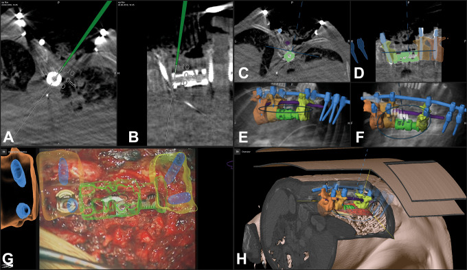
Abstract
Study Design:
A prospective, case-based, observational study.
Objectives:
To investigate how microscope-based augmented reality (AR) support can be utilized in various types of spine surgery.
Methods:
In 42 spinal procedures (12 intra- and 8 extradural tumors, 7 other intradural lesions, 11 degenerative cases, 2 infections, and 2 deformities) AR was implemented using operating microscope head-up displays (HUDs). Intraoperative low-dose computed tomography was used for automatic registration. Nonlinear image registration was applied to integrate multimodality preoperative images. Target and risk structures displayed by AR were defined in preoperative images by automatic anatomical mapping and additional manual segmentation.
Results:
AR could be successfully applied in all 42 cases. Low-dose protocols ensured a low radiation exposure for registration scanning (effective dose cervical 0.29 ± 0.17 mSv, thoracic 3.40 ± 2.38 mSv, lumbar 3.05 ± 0.89 mSv). A low registration error (0.87 ± 0.28 mm) resulted in a reliable AR representation with a close matching of visualized objects and reality, distinctly supporting anatomical orientation in the surgical field. Flexible AR visualization applying either the microscope HUD or video superimposition, including the ability to selectively activate objects of interest, as well as different display modes allowed a smooth integration in the surgical workflow, without disturbing the actual procedure. On average, 7.1 ± 4.6 objects were displayed visualizing target and risk structures reliably.
Conclusions:
Microscope-based AR can be applied successfully to various kinds of spinal procedures. AR improves anatomical orientation in the surgical field supporting the surgeon, as well as it offers a potential tool for education.
Keywords: augmented reality, head-up display, intraoperative computed tomography, low-dose computed tomography, microscope-based navigation, navigation registration, nonlinear registration
Introduction
Head-up displays (HUDs) integrated in operating microscopes provide a straightforward implementation of augmented reality (AR) when combined with standard navigation. The concept of superimposing structures that were segmented in preoperative image data, was already developed in the 1980s1,2 and was broadly implemented in cranial neurosurgery since the mid-1990s.3-6 This microscope-based AR became more and more sophisticated over the years by a better 3-dimensional (3D) object representation and an improved immersive display of these objects, as well as by integrating various kinds of preoperative imaging data, resulting in multimodality AR.7-9 However, despite navigation is also available in spine surgery for many years, only recently mainly head-mounted devices (HMDs) were investigated for implementation of AR in spine procedures.10-16 A major challenge in most of these setups is that in contrast to the phantom experiments, where a clear outline of a structure can be optically adjusted to the AR visualization by the HMD, in real surgical situations such an optical matching registration is not possible, so registration procedures like they are implemented for spinal navigation have to be applied, for example, point matching or intraoperative imaging.
The flexibility of the spine causes that the registration process, that is, adjusting image space and real space, is even more challenging than in cranial navigation. Preoperative images, which are regularly used to define the structures that are visualized by AR in cranial procedures, usually do not reflect the actual 3D anatomy and alignment of the spine, since patient positioning on the operating room table and during preoperative imaging differs, so the alignment of the vertebra does not match. Therefore, we implemented a combination of intraoperative computed tomography (iCT)–based automatic patient registration and nonlinear image registration to minimize overall registration errors when applying AR for spine surgery.17
This prospective observational study summarizes our experience we gained with microscope-based AR support in 42 procedures among them different approaches covering the whole spine, mainly for intradural tumors and lesions, extradural tumors, and degenerative diseases. The main focus of this article is on the feasibility of AR for spine surgery, as well as on the radiation exposure that is necessary, for iCT-based automatic registration to achieve high reliability.
Materials and Methods
Patients
Between July 2018 and April 2019, 42 spinal procedures were performed with AR support. Patient selection was random to select different procedures to be tested. This includes a total of 41 patients (23 females, 18 males; age range: 19-84 years, mean age 57.3 ± 14.7 years) undergoing surgery for tumors (n = 20; intradural tumors 12, extradural tumors 8), other intradural lesions (n = 7), degenerative diseases (n = 11), infection (n = 2), or deformity (1 patient who was operated upon twice). Patient data and procedure details are summarized in Table 1. Informed consent was obtained from all individual patients included in this prospective observational study. We obtained ethics approval for prospective archiving clinical and technical data applying intraoperative imaging and navigation (study no. 99/18).
Table 1.
Patient Characteristics.
| No. | Age, y | Sex | Diagnosis | Approach | Procedure |
|---|---|---|---|---|---|
| 1 | 65 | Female | Meningioma WHO I C2-C3 | Posterior cervical | Laminectomy C2-C3, resection |
| 2 | 59 | Male | Metastasis squamous cell lung carcinoma C0-C3 | Posterior cervical | Craniotomy posterior fossa, laminectomy C1-C3, resection |
| 3 | 75 | Female | Metastasis mamma carcinoma L2 | Lateral lumbar | Tumor resection, vertebral body replacement L2 |
| 4 | 51 | Male | Suspected intradural lymphoma L1-L3 | Posterior lumbar | Laminectomy, biopsy |
| 5 | 61 | Male | Recurrent lumbar disc herniation L3/4 right | Posterior lumbar | Removal of free disc fragment and spondylodesis L3/4 (transforaminal lumbar interbody fusion [TLIF]) |
| 6 | 75 | Male | Small-cell lung carcinoma T8 and T9 | Posterior thoracic | Posterior fixation T6 - T11, hemilaminectomy T8-T9, decompression, and biopsy |
| 7 | 59 | Male | Neuroendocrine carcinoma metastasis T6 | Posterior thoracic | Laminectomy T6, complete resection |
| 8 | 54 | Male | Spondylodiscitis T7/8 and T8/9 | Posterior thoracic | Posterior fixation T5-T11, decompression T8 |
| 9 | 31 | Female | Benign cystic lesion T11-T12 | Posterior thoracic | Partial laminectomy T11, laminectomy T12, cyst drainage |
| 10 | 61 | Female | Adhesive arachnoiditis T3-T4 | Posterior thoracic | Laminoplasty T3-T4, intradural decompression |
| 11 | 68 | Female | Mesenchymal chondrosarcoma T2 and T6 | Posterior thoracic | Posterior fixation T1-T4, laminectomy T6, decompression, partial resection |
| 12 | 73 | Female | Spinal stenosis C5 + C6, cervical myelopathy | Anterior cervical | Vertebral body replacement C5 + C6 and C4-C7 lateral mass fixation |
| 13 | 60 | Male | Recurrent lumbar disc herniation L4/5 right | Posterior lumbar | Removal of free disc fragment/decompression |
| 14 | 64 | Male | Small-cell lung carcinoma T1 | Anterior thoracic | Corpectomy T1, vertebral body replacement T1, posterior fixation C7-C2 |
| 15 | 38 | Female | Adjacent level disease after spondylodesis/pseudarthrosis L5/S1 | Posterior lumbar | L5/S1 cage revision, revision S1 screws, new S2 screws |
| 16 | 58 | Female | Spondylodiscitis destruction of T8 and T9, previous fixation T4-T11 | Posterior thoracic | Vertebral body replacement T8 and T9 |
| 17 | 66 | Male | Meningioma WHO I T7 | Posterior thoracic | Laminectomy T6-T8, complete resection |
| 18 | 44 | Male | Lateral disc herniation L3/L4 right | Posterior lumbar paramedian | Paramedian approach, removal of disc fragment |
| 19 | 84 | Female | Lateral disc herniation L3/L4 left | Posterior lumbar paramedian | Paramedian approach, removal of disc fragment |
| 20 | 84 | Female | Meningioma WHO I T1-T2 | Posterior thoracic | Laminectomy T1-T2, complete resection |
| 21 | 57 | Female | Meningioma WHO I C1 | Posterior cervical | Laminectomy C1, complete resection |
| 22 | 19 | Female | Intradural adhesions after resection of a chondrosarcoma T5 and T6 | Posterior thoracic | Intradural decompression T5-T6 |
| 23 | 46 | Male | Deformity C2-C5 | Anterior cervical | Decompression, vertebral body replacement C2 |
| 24 | 46 | Male | Deformity C2-C5, revision | Anterior cervical | Refixation of vertebral body replacement C2 |
| 25 | 58 | Female | Metastasis adenocarcinoma of the lung T1-T2 | Posterior thoracic | Laminectomy T1-T2, decompression, intradural biopsy, duraplasty |
| 26 | 50 | Male | Medial disc herniation T8/9 (after laminectomy) | Lateral thoracic | Lateral approach, removal of calcified disc herniation and posterior fixation T8/T9 |
| 27 | 67 | Female | Lateral disc herniation L4/L5 left | Posterior lumbar paramedian | Paramedian approach, removal of disc fragment |
| 28 | 38 | Female | Intradural myelon tethering after trauma T3/T4 | Posterior thoracic | Laminectomy T3-T4, de-tethering |
| 29 | 76 | Female | Meningioma WHO I T11-T12 | Posterior thoracic | Laminectomy T11-T12, complete resection |
| 30 | 66 | Female | Meningioma WHO I C1 | Posterior cervical | Laminectomy C1, complete resection |
| 31 | 58 | Male | Arteriovenous fistula L4 | Posterior lumbar | Laminectomy L4, occlusion of fistula |
| 32 | 29 | Male | Arachnoidal cyst | Posterior cervical | Laminectomy C1, complete resection |
| 33 | 59 | Male | Glioma WHO II C0-C2 | Posterior cervical | Craniotomy posterior fossa, laminectomy C1, biopsy |
| 34 | 52 | Female | Neurinoma WHO I L2 left | Lateral lumbar | Paraspinal approach, complete resection |
| 35 | 62 | Female | Medial disc herniation T8/9 | Lateral thoracic | Lateral approach, removal of disc herniation |
| 36 | 38 | Female | Ependymoma WHO II C7-T2 | Posterior cervicothoracic | Laminectomy C7-T2, complete resection |
| 37 | 61 | Male | Foraminal stenosis L4/L5 left, compression L4 | Posterior lumbar | Midline posterior approach, decompression |
| 38 | 50 | Female | Osteoclastoma L1 | Lateral lumbar | Corpectomy L1, vertebral body replacement L1, posterior fixation T11-L3 |
| 39 | 36 | Female | Hemangioblastoma WHO I C1 | Posterior cervical | Laminectomy C1, complete resection |
| 40 | 55 | Male | Intradural fibroma L3/L4 | Posterior lumbar | Laminectomy L3, complete intradural resection |
| 41 | 81 | Female | Metastasis thyroid cancer L3 | Posterior lumbar | Laminectomy L3, resection of extradural tumor |
| 42 | 60 | Male | Lateral disc herniation L4/L5 left | Posterior lumbar paramedian | Paramedian approach, removal of disc fragment |
Preoperative Imaging and Object Definition
Preoperative image data were used for anatomical mapping (mapping element software, Brainlab, Munich, Germany) to automatically segment the vertebra. Each vertebra was assigned with a unique color. Additional manual segmentation (smart brush element software, Brainlab) was applied to correct the results of automatic segmentation in case of erroneous level assignment and insufficient 3D outlining. This software tool was also used to segment the target and risk structures (tumor, cysts, vessels, disc fragment, etc). In case preoperative multimodality data were integrated, to begin with these data were rigidly registered (image fusion element software, Brainlab). If this image fusion showed a mismatch in the area of interest due to the flexibility of the spine resulting, for example, in a changed sagittal alignment between the different imaging time points, non-linear image fusion was performed (spine curvature correction element software, Brainlab). The final alignment was mainly checked by observing whether the segmented outlines of the vertebra matched closely.
Intraoperative Setting
The patient was positioned in supine, lateral, or prone position directly on the operating table of a 32-slice, movable CT scanner (AIRO, Brainlab). Details of the surgical setting are published elsewhere.17 Depending on the approach the reference array was attached on a spinous process (larger posterior thoracic and larger median lumbar approaches), at the head clamp (in upper posterior cervical approaches), at the retractor system (in lateral thoracic and lateral lumbar approaches), or taped firmly on the skin in case of small approaches (anterior cervical, posterior lower cervical, anterior upper thoracic, posterior thoracic, posterior median lumbar, and posterior paramedian lumbar). For calculation of the target registration error (TRE), adhesive skin fiducials were placed around the skin incision prior draping. Registration scanning was performed after performing the surgical approach to the spine and retractor placement to prevent positional shifting due to the approach preparation. Low-dose scan protocols were used for the iCT registration scan (sinus-80%: axial acquisition, 7.07 mA, 120 kV; c-spine-70%: helical acquisition, 28 mA, 120 kV; t-spine-70%: helical acquisition, 33 mA, 120 kV, with weight modulation; l-spine-70%: helical acquisition, 33 mA, 120 kV, with weight modulation; neonate full body: helical acquisition, 7 mA, 80 kV).
The effective dose (ED) was calculated by multiplying the total dose length product (DLP) referring to a phantom with a diameter of 16 cm (cervical) or 32 cm (thoracic and lumbar) with a ED/DLP conversion factor (cervical: 5.4µSv/Gy·cm, thoracic: 17.8 µSv/Gy·cm, lumbar: 19.8µSv/Gy·cm), which if necessary was weighted according to the amount of vertebra covered in the cervicothoracic or thoracolumbar junction.
After the iCT images were send to the navigation system, automatic registration took place and registration accuracy was documented applying a navigation pointer selecting characteristic anatomical and artificial landmarks, as well as the skin fiducials for measuring the TRE. Then the iCT image data was registered with the preoperative images, including the preoperatively defined objects in the same manner as the preoperative image data were registered (see above).
Augmented Reality
After automatic registration was checked, the HUD of the operating microscopes Pentero or Pentero 900 (Zeiss, Oberkochen, Germany) was calibrated by centering the microscope over the registration array so that the microscope crosshair pointed into the central divot of the registration array. Then the displayed outline of the registration array could be checked with the real outline of the array and adjusted if necessary, to achieve an optimal matching. Immediately afterward, full AR support was available. In general, each object could be switched on or off, as well as the color that was assigned to the object could be altered to allow a better distinction from the background, which was necessary in certain situations, when the background color resembled the color of the object too much. Using the HUD for AR provided two different display modes, either the colored objects were displayed in a line-mode or a 3D representation. The line-mode representation depicted a solid line showing the extent of the object perpendicular to the viewing axis of the microscope in the focal plane in combination with a dotted line showing the maximum extent of the object beyond the focal plane. The 3D representation visualized the objects as 3D objects in a semitransparent way with contours in varying thickness giving an impression on the 3D shape. Additionally, to selectively switch on or off certain objects, the HUD itself could be switched off completely to allow an undisturbed view of the surgical field at any time. In these situations, AR was still visible as a visualization showing the superimposition of the objects on the microscope video on monitors close to the surgical field. Additional to this display a 3D representation of the image data in combination with the video frame, illustrating how the video frame was actually placed in relation to the 3D data, was available, as well as a target visualization of the 3D objects alone, and standard navigational views in probe’s eye view, inline views, and axial, coronal and sagittal views. In all these views, the center of the microscope in the focal plane was visualized as a crosshair corresponding to the crosshair in the microscope view itself. Additionally, blue lines delineated the viewing axis of the microscope and the extent of the viewing field, if the image representation was not rectangular to the microscope viewing axis, the viewing plane was represented as an oval or circle. This latter mode was visible if the navigation pointer was placed in the surgical field, while applying microscope-based AR, allowing additional measurements in the surgical field during microscope usage.
Results
AR Was Successfully Implemented in All 42 Procedures
Preoperative automatic mapping for vertebra segmentation had to be adjusted by additional manual segmentation especially in cases of previous surgery and large lesions deforming standard anatomy. Preoperative image processing, which was done normally on the day before surgery, including automatic segmentation, linear and nonlinear registration of multimodality images, as well as manual fine-tuning depended mainly on the number of objects integrated in the setup, as well as, how meticulously the outlines of each vertebra were fine-tuned to provide an appealing 3D visualization. In total, this process ranged from 5 to 30 minutes.
Among the 42 cases, the patient was placed in prone position in 33 procedures, 5 patients were operated in lateral position, and 4 in supine. The selected approaches were: 3 anterior cervical, 7 posterior cervical, 1 posterior cervicothoracic, 1 anterior thoracic, 2 lateral thoracic, 13 posterior thoracic, 3 lateral lumbar, 8 posterior lumbar midline, and 4 posterior lumbar paramedian (see Table 1).
Intraoperative registration scanning, starting with sterile covering of the surgical field, adjustment of the navigation camera, definition of the scan range, the scout scan, and the actual iCT registration scan needed in most of the cases about 5 minutes. After registration of the iCT images with the preoperative planning and microscope calibration AR was immediately available.
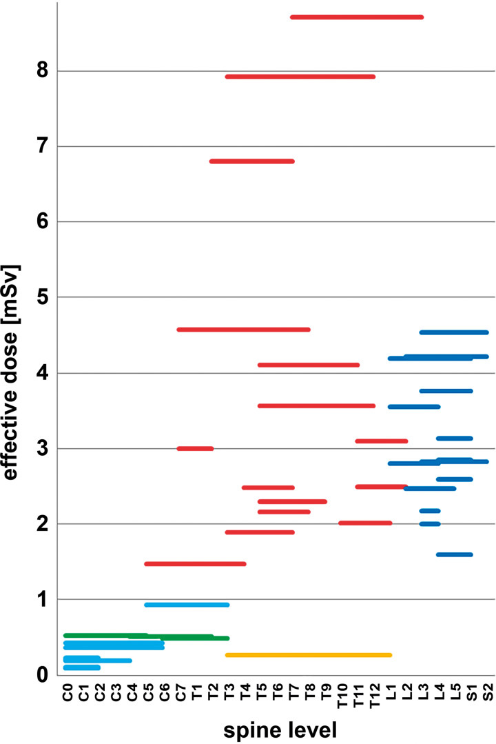
The total ED (summarizing scout scan and iCT registration scan) ranged from 0.09 to 8.71 mSv. Grouped by the 3 spine sections the total ED was: cervical 0.29 ± 0.17 mSv (mean ± standard deviation [SD]) (range 0.09-0.53 mSv); thoracic 3.40 ± 2.38 mSv (range 0.27-8.71 mSv); lumbar 3.05 ± 0.89 mSv (range 1.59-4.54 mSv). For reduction of radiation exposure, we could omit the scout scan in 8 patients by defining the scan range on the draping with a marker pen. This further reduced overall ED, which is of high relevance, because the scout scan itself could contribute significantly to the overall ED. In 34 patients, the ED of the scout scan ranged from 0.05 to 0.92 mSv (mean ± SD: 0.32 ± 0.20 mSv) with a scout scan length of: 101 to 384 mm (mean ± SD: 187 ± 68 mm). Figure 1 depicts the total ED for all 42 cases classified by the applied scan protocol in relation to the vertebra covered by the iCT registration scan. Weight modulation resulted in different EDs in comparable scan ranges. The iCT scan length varied between 60 and 312 mm; cervical 60 to 176 mm (mean ± SD: 93.3 ± 37.7 mm); thoracic 86 to 321 mm (mean ± SD: 158.7 ± 76.3 mm); lumbar 81 to 213 mm (mean ± SD: 132.6 ± 44.4 mm).
Figure 1.
Total effective dose (ED; scout and intraoperative computed tomography [iCT] scan) visualized for all 42 procedures in relation to the scanned levels and scan protocol (light blue: sinus-80%; green: c-spine-70%; red: t-spine-70%; orange: neonate full body; dark blue: l-spine-70%) (note that the length of each bar represents the vertebra included in the scan range and not the actual scan length).
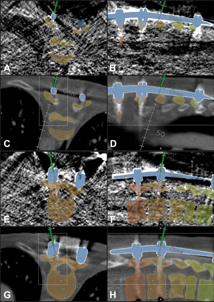
Further reduction of radiation exposure was possible, as demonstrated in case 16 in which we applied a neonate protocol that resulted in an extremely reduced ED of 0.27 mSv despite of a scan length of 244 mm. This was possible due to the fact that in a previous surgery this patient had received an instrumentation. These implants allowed a reliable registration despite the low image quality of the neonate protocol registration scan (Figure 2). Compared with case 36, which was scanned with a nearly identical scan length of 248 mm in the thoracic region (t-spine-70% protocol with an ED of 8.71 mSv), this is a reduction of a factor of 32 due to the neonate protocol.
Figure 2.
In a 58-year-old female patient with a destruction of T8 and T9 due to spondylodiscitis with previous fixation T4-T11 (case 16), a neonate protocol was used for intraoperative computed tomography (iCT)–based patient registration; registration with preoperative image data was possible due to the previous instrumentation, which was visible in preoperative, as well as in the blurry iCT images, note that the outline of the vertebra is not clearly visible in the neonate protocol images; in A-D, the pointer is placed on the rod segmented in blue; in E-H, the pointer is placed in the head of the right screw of T10 (A/B/E/F: neonate protocol iCT; C/D/G/H: preoperative CT) (A/C, B/D, E/G, and F/H show corresponding images after registration) (A/C/E/G: axial; B/D/F/H: sagittal view).
Landmark checks proved the high overall registration accuracy, the TRE ranged from 0.45 to 1.29 mm (mean ± SD: 0.87 ± 0.28 mm). Repeated landmark checks ensured that during surgery there was no positional shifting decreasing accuracy. These repeated landmark checks were mandatory if the system issued a warning, that a movement of the reference array was detected, indicating a potential collision of an instrument with the reference array, which means positional shifting.
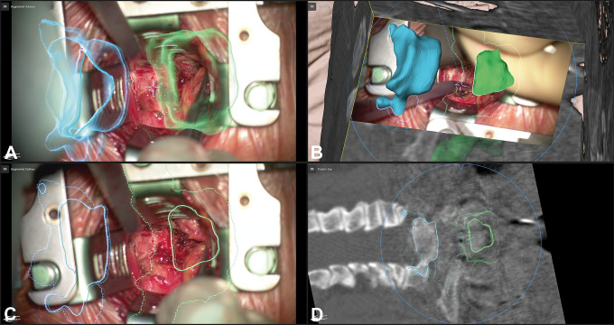
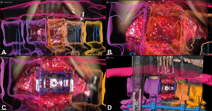
The number of objects segmented for display by AR ranged from 1 to 25 (mean ± SD: 7.1 ± 4.6). During surgery, this number was often reduced to 3 to 4 objects that were actually displayed simultaneously; in case of an intradural tumor preparation, this was often further reduced just to the tumor object. In case the AR display obscured the clear view of the surgical field, the HUD was switched off completely and was switched on again if requested. The HUD was switched off and turned on again on an average of 3 to 4 times during all surgeries to obtain an unobscured view for some moments. The frequency was quite variable comparing the different procedures and reached a maximum in the intramedullary lesions, where sometimes the AR visualization blurred the identification of the border between the lesion and the medulla during microsurgical preparation. In these cases, the HUD was turned off also for longer periods of preparation. AR was still visible for the surgeon and the team in case the HUD was switched off, because an AR visualization as video superimposition was constantly provided on monitors in viewing range. The 2 AR display modes were both used; the line-mode representation offered sometimes a better overview compared with the full 3D visualization, because the thicker lines of the 3D representation sometimes prevented a clear view of the surgical field, which was of special importance in the intramedullary tumors. On the other hand, the 3D mode gave a more intuitive depth perception when looking at the scenery at low magnification. For comparison of both display modes see Figure 6A-C. The hand-eye coordination was smooth as there was no need to look away from the surgical field unless the HUD display was activated.
Figure 6.
A 64-year-old male patient (case 14) undergoing corpectomy of T1 via an anterior approach for removal of a small cell lung carcinoma metastasis and stabilization with an expandable implant; the neighboring vertebrae are visualized (C7: blue; T2: green), A/C allows a comparison of the 2 augmented reality (AR) display modes (A: AR as 3-dimensional [3D] representation; B: 3D overview display visualizing how the video frame relates to the 3D anatomy with the objects rendered in 3D; C: AR as line-mode representation; D: probe’s eye view of intraoperative computed tomography (iCT) images, the blue circle represents the microscope viewing field).
Illustrative Cases
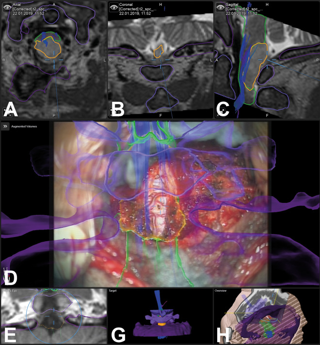
Figure 3 illustrates an example for intradural tumor surgery with a biopsy of a glioma reaching from C0 to C2 (case 33), a total of 6 objects were visualized by AR (tumor, brain stem and medulla, C0, C1, C2, and tractography). An example for nontumorous intradural lesions is a dural arteriovenous fistula below the right L4 pedicle in a patient (case 31) with a complicated anatomical situation with an intra- and extradural lipoma and a tethered cord due to a spina bifida occulta. The area of the fistula was segmented in the preoperative images and visualized by AR (Figures 4 and 5). Figures 6 and 7 are examples for extradural tumor surgery. Figure 6 illustrates a corpectomy of T1 via an anterior approach for removal of a metastasis of a small cell lung carcinoma and stabilization (case 14). In Figure 7, an osteoclastoma in L1 was removed and an expandable cage was inserted via a lateral approach (case 38; a video of this case demonstrating HUD-based AR can be found in the Supplemental Material). An example for AR in infectious diseases is shown in Figures 8 and 9; a posterior vertebral body replacement is performed via a posterior approach (case 16); this is the case in which the neonate scan protocol could be applied for registration (see above). Repeated scans in the cases with vertebral body replacements offered an additional possibility to check overall AR accuracy. The implants were segmented and in all such cases a very close matching of the visualized implant AR object matched reality (see Figures 7C/D and 9G). An example for AR in degenerative surgery is depicted in Figure 10 with a patient undergoing surgery for a recurrent disc (case 13).
Figure 3.
In a 59-year-old male patient, a glioma was biopsied with augmented reality (AR) support (case 33); the tumor object is segmented in yellow, the brain stem and medulla are segmented in green, C0/C1/C2 are visualized in different shades of violet, additionally tractography data are visualized (A: axial; B: coronal, C: sagittal T2-weighted images, D: AR visualization; E: probe’s eye view; F: target view; G: 3-dimensional overview)
Figure 4.
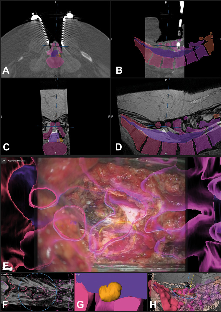
A 58-year-old male patient (case 31) with an arterio-venous fistula below the right pedicle L4 was visualized with augmented reality (AR). The surgical situation was complicated due to a spina bifida occulta with an intra- and extradural lipoma and a tethered cord; the area where the fistula was expected was segmented in orange, additionally the dural sac and the vertebrae T12-S5 were segmented in individual colors and visualized by AR; the situation after laminectomy of L4 and preparation of the extra- to intradural transition of the lipoma is displayed, the blue crosshair in E depicts the center of the microscope view and corresponds to the position depicted in A-D and F and H (A: axial, B: sagittal view of registration intraoperative computed tomography [iCT]; corresponding axial (C) and sagittal view (D) of preoperative T2-weighted images; E: AR view with all objects activated; F: probe’s eye view of T2-weighted images; G: enlarged target view; H: 3-dimensional (3D) overview depicting how the video frame is related to the 3D anatomy)
Figure 5.
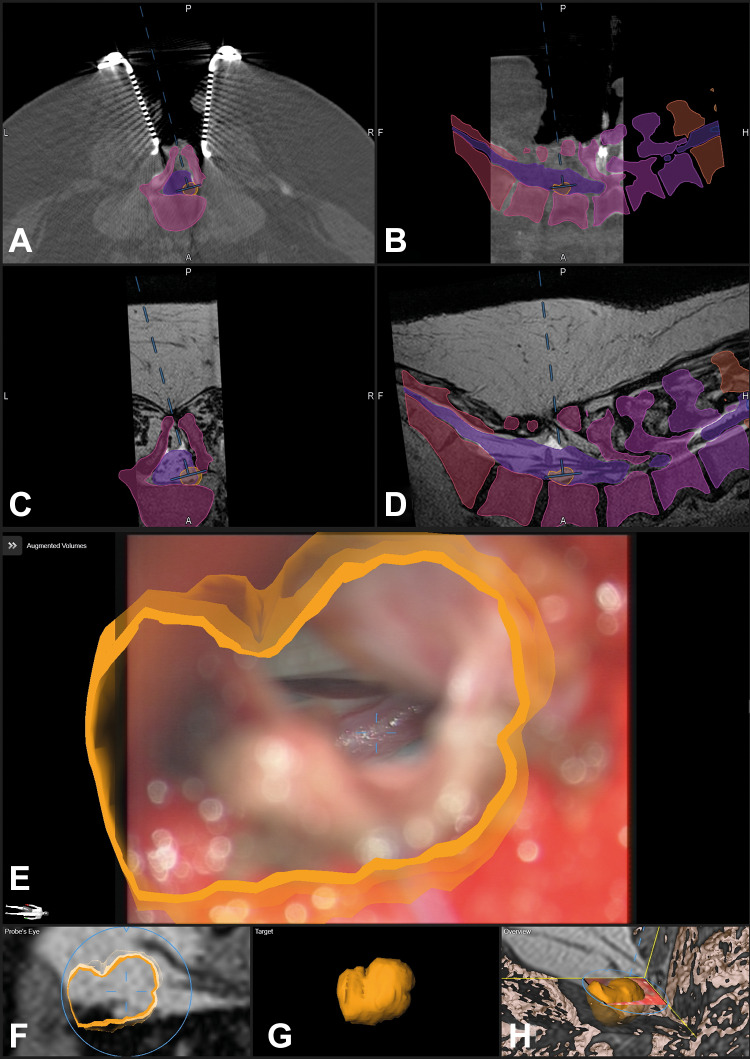
The same patient as in Figure 4 after dural opening; the fistula is clearly visible in the enlarged view and enclosed by the orange contour (E), note that the blue lines representing the microscope-viewing field are much smaller compared with Figure 4 representing the enlarged microscope magnification (A: axial, B: sagittal view of registration intraoperative computed tomography (iCT); corresponding axial (C) and sagittal view (D) of preoperative T2-weighted images; E: enlarged augmented reality (AR) view, only the target object is activated; F: probe’s eye view of T2-weighted images; G: enlarged target view; H: 3-dimensional (3D) overview depicting how the video frame is related to the 3D anatomy).
Figure 7.
A 50-year-old female patient (case 38) with an osteoclastoma in L1 that was removed and an expandable implant was inserted via a lateral approach; A: augmented reality (AR) display with the 3-dimensional (3D) representation of the vertebrae T11-L3 and the tumor outline in L1 (orange), additionally the fixation T11/T12-L2/L3 that was implanted before is visualized in blue; B: enlarged view of A with the pointer in the surgical field, the pointer tip is visualized as green crosshair, while the microscope focus point is visualized as a blue crosshair; C: after removal of the tumor and insertion of the expandable cage a repeated intraoperative computed tomography (iCT) was performed, in which the implant was segmented and subsequently visualized by AR (dark blue) showing the close matching of AR object and implant; D: overview display of C, depicting how the video frame is placed in relation to the 3D image anatomy.
Figure 8.
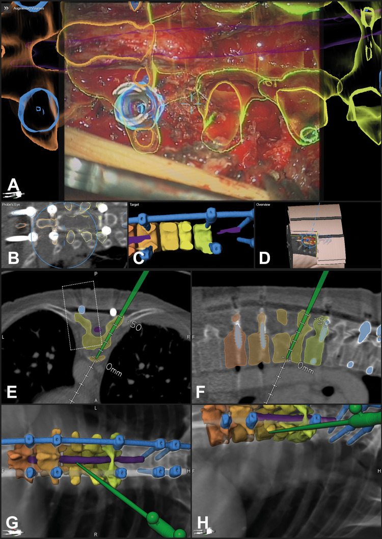
The same patient (case 16) as in Figure 2—a posterior vertebral body replacement was performed via a posterior approach; A: augmented reality (AR) view with the 3-dimensional (3D) outline of the vertebrae T7-T11, the myelon is segmented in violet, and the implants are segmented in blue (screws and rod on the left side, for the approach the right rod was removed), a close matching of the screw head and the AR representation is visible; B: probe’s eye view of preoperative computed tomography (CT) images; C: target view; D: 3D video overview; E-H: navigation view of preoperative images with the pointer inserted in the resection cavity at the ventral border of T8/T9 (E: axial, F: sagittal view, G/H: 3-D representation in different viewing angles).
Figure 9.
The same patient as in Figures 2 and 8 after implantation of the expandable cage and repeated intraoperative computed tomography (iCT) documenting the high registration accuracy in updated augmented reality (AR; the new implant is segmented in green); A/B: axial and sagittal view with the navigation pointer tip placed on the implant; C-F: navigation view with the operating microscope (C: axial; D: sagittal view; E/F: 3-dimensional (3D) rendering in different viewing angles, the microscope field of view is visualized as a blue oval); G: AR view with the new implant demonstrating the close matching of AR and reality; H: 3D video overview, showing the relation of the video frame and 3D anatomy.
Figure 10.
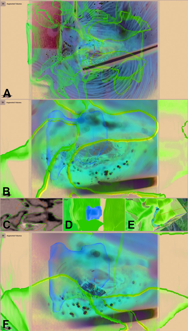
A 60-year-old male patient (case 13) with a recurrent disc in L4/L5 on the right side; the disc fragment and the vertebrae L4, L5, and S1 are visualized by augmented reality (AR); A: AR view after exposure of the spinal canal and removal of scar tissue; B: enlarged AR view with the visible spinal dura; C: probe’s eye view; D: target view; E: 3-dimensional video overview; F: AR view while the disc fragment is removed showing the close matching.
Discussion
Microscope-based AR can be successfully applied in spinal surgery. We had implemented microscope-based AR using commercially available system components17,18 after the feasibility of microscope-based AR had been shown in a visualization of osteotomy planes19 and in cervical foraminotomy.20 In our observational study on 42 patients, AR supported various kinds of spine procedures and facilitated anatomical orientation in the surgical field in all cases. Target and risk structures could be reliably visualized. AR demonstrated its benefit especially in challenging anatomical situations, like reoperations and complex anatomical situations, as well as it will be beneficial in aiding the training of residents for a quicker and better understanding of anatomy.21 All spinal procedures that are suitable for microscope usage are candidates for microscope HUD-based AR, independent of the spine region, patient positioning, and the approach to the spine.
For a reliable use of AR, high registration accuracy, as well as correct AR calibration are mandatory. Automatic registration based on intraoperative imaging in combination with nonlinear registration of preoperative image data accounting for the flexibility of the spine, resulted in a very low overall registration error of 0.87 ± 0.28 mm. The microscope HUD calibration was routinely checked in the process of initializing AR use in each procedure, by controlling the exact matching of the visualized AR outlines and the AR 3D representation of the reference array with reality and the possibility to adjust this matching if needed. Additionally, overall AR accuracy also depends on a correct segmentation of the visualized structures, as well as, a correct linear or nonlinear registration of the various multimodality images.
Automatic, that is, user-independent patient registration ensures the high registration accuracy. Intraoperative imaging is key for this automatic registration process.22 We used iCT for intraoperative registration imaging, which has the principal disadvantage of radiation exposure for the patient. Since radiation exposure has the potential side effect to induce cancer, we used low-dose protocols and tried to minimize the scan range for registration. However, especially in the thoracic region for an unambiguous vertebra identification of correct level registration longer scan ranges were often necessary resulting in higher EDs. Low-dose protocols resulted in a mean ED for the cervical region of 0.29 mSv, for the thoracic region of 3.40 mSv, and for the lumbar region of 3.05 mSv. These doses for the thoracic and lumbar region are in the range of the typical individual exposure of radiation of a US citizen from natural background sources of about 3 mSv per year. Publications analyzing the mean radiation exposure by standard diagnostic CT scans report 3 mSv for neck examinations and 7 mSv for spine examinations,23 scans being classified as chest or abdominal scans reach mean EDs of 11 and 17 mSv.24
In some cases, we could even pass the scout scan, which contributed substantially to the total ED, especially in case of scanning with low-dose protocols. Under special conditions, a further reduction of radiation exposure is possible, as we could demonstrate by scanning applying a neonate protocol that resulted in an extremely reduced ED of 0.27 mSv despite of a scan length of 244 mm in the mid-thoracic region. This was possible because of the fact that the patient undergoing vertebral body replacement for spondylodiscitis, had received posterior screw fixation in a previous surgery. Despite the high image noise due to the extreme low-dose neonate protocol these implants could still be visualized in their 3D geometry and could be registered with preoperative image data reliably. A patient scanned with a nearly identical scan length received despite a low-dose protocol (−70%) was used an ED of 32-fold compared to the application of the neonate protocol.
The challenge in finding the lowest dose possible is to individually define the threshold when extreme low-dose scanning results in an increase in image noise that prevents reliable registration with preoperative image data. This depends on the scan region, patient weight, and whether there are potential artificial landmarks that might allow further reduction of radiation exposure. Analyzing the fundamental physical limits shows that there should be still potential for further reduction of radiation exposure.25
Alternatives for radiation-free registration are single level point to point registrations, as often used in standard navigation for pedicle screw implantation. However, compared with intraoperative imaging-based registration, point to point registration is less accurate and more time consuming and can be used reliably only for one level.26 Additionally, these techniques are only validated for posterior approaches, so they cannot be applied in anterior or lateral approaches, as well as they are not suitable for percutaneous procedures.
Other intraoperative imaging registration alternatives are intraoperative magnetic resonance imaging (iMRI) and intraoperative ultrasound (iUS). Skin fiducial–based registration in combination with iMRI was demonstrated for spinal interstitial laser thermotherapy.27 However, up to now there is no report on an automatic registration setting for spine surgery when applying iMRI, as it is implemented for cranial procedures supported by iMRI with a marker array that is integrated into the imaging coil. The known geometry of the marker array can be automatically detected in the intraoperative images, resulting in automatic patient registration.28 Attempts at applying iUS for registration of spinal structures are still in an experimental state and not yet accurate enough.29,30
Potential intraoperative pitfalls decreasing AR accuracy relate to intraoperative events changing the structure or alignment of the spine, so performing the registration scan after approaching the spine and placement of the retractor systems is recommended. Positional shifting, that is, a movement of the reference array in relation to the surgical site, is an additional challenge, especially in case the reference array is not rigidly fixed to the spine or related bony structures like the iliac crest. Repeated landmark checks are advised, especially in case something collided with the reference array and the system is issuing a warning of a potential movement of the array. In case of decreased accuracy, repeated intraoperative registration scanning offers the possibility to restore AR accuracy by updating the image and registration data.
Applying the operating microscope HUDs for AR did not disrupt the surgical workflow. There is no problem in hand-eye coordination and no parallax problem since AR can be visualized without being forced to look away from the surgical site as it might be necessary in AR settings displaying the AR information on separate monitors only.31 The perception location on the patient, which is ensured by the microscope HUD is much more intuitive.32 Both AR display modes provide an intuitive impression of the extent of structure perpendicular to the viewing axis, and a good depth perception either by displaying a 3D-shaped object in 3D mode or by displaying a dotted line for the maximum extent of a structure beyond the focus plane in line-mode AR representation. In clinical practice, availability of the different AR modes was beneficial. Sometimes the 3D mode obscured the clear view of the surgical site, then the line-mode AR provided a better alternative by a more low-key AR representation. Additionally, the flexible usage of AR with its possibility to selectively activate and deactivate objects, prevented an information overflow in the surgical field. On average, 7 different objects were prepared for intraoperative AR visualization, however the actual number was often reduced to a lesser number in the critical phases of surgery to maintain a good overview in the surgical field. In case an AR-free clear overview of the surgical field was needed, the HUD could be easily switched off and activated again repeatedly. In case the HUD was deactivated, AR was still presented as video overlay on monitors in close viewing range, providing immediate orientation if needed.
The AR display has to become even more immersive, so that the impression that the visualized objects are just overlaid on top of surgical site is prevented. Potential improvements relate to the technical side of the HUD, as well as the AR rendering itself. A higher resolution of the HUD is mandatory in the future since 4K video systems will become standard, otherwise the AR visualization would appear pixelated. However, the resolution of the image data, which is the base for object generation is less than the optical or video resolution, so that for object generation sophisticated smoothing and interpolation are required. Additionally, the contrast ability and adjustment of individual objects and colors of the HUD has to be improved, because large changes of luminance can occur at any time in the surgical field. Furthermore, there is room for improvement in the AR rendering itself, how the objects are visualized in case they are covered by structures in the surgical field, leading to a merged reality situation, where potentially the AR objects could also interact with reality. All these improved graphics, higher resolutions, and quicker renderings of AR will need increasing computing power to avoid delays, which otherwise would disrupt immersiveness.33
In case of procedures where an operating microscope is not necessary, for example, in percutaneous procedures, HMDs are an interesting alternative to the operating microscope for AR in spine surgery. HMDs were developed as early as 196834 and first applied in neurosurgery in the mid-1990s.35,36 Wearable devices like HMDs are investigated in different surgical setups.10-16 In a phantom study, an optical see-through HMD offering a mixed reality experience was tested successfully for kyphoplasty.12 For visualization, a “world-anchored” view was defined by the operator by locking the display to a specific position in the environment. Such an approach is possible for phantom studies, where a clear outline of the phantom and the AR visualization is visible, and which can be adjusted easily. In real-world surgery, this kind of registration is not possible, so that sophisticated methods for patient registration, like intraoperative imaging, have to be implemented. When using HMDs like the HUDs in operating microscopes for AR visualization, it is also crucial that a 3D tracking of the HMD during surgery is established.37,38
Endoscopic spine procedures potentially would also benefit from AR support, since the surgical orientation might be complicated and there might be a substantial learning period of such procedures before an adequate performance can be achieved.39 When implementing AR support for endoscopic procedures, it has to be taken into account that the endoscope video image is optically distorted. A prototype setup using wireframes for AR representation in endoscopic transsphenoidal surgery was tested,40 and recently, an implementation of AR for intraventricular neuroendoscopy was reported41; both setups might also be suitable for AR implementation in endoscopic spinal procedures. AR will also be an important addition when exoscopes are used for spine procedures.42
Apart from AR displays on monitors,31 an alternative to HUD- or HMD-based AR might be projection systems offering direct augmentation by spatial AR projecting images directly onto the physical object surface without the need to carry or wear any additional display device.33 Systems providing such an augmentation in the open space would increase the surgeon comfort compared with wearing heavy HMDs for longer procedures and would improve sharing and collaboration during a procedure; however up to now, such systems are not yet available.
Among the limitations of our study is that it is difficult to exactly measure the additional benefit of the AR application in each individual procedure. Usability questionnaires might be a tool to document surgeon acceptance.15 Since in this study the technique was used by a small team that also initially implemented the technique, such a survey would probably have a positive bias, so that these surveys will make more sense when surgeons that were not yet familiar with the technique can use it. The effects of AR in spine surgery for resident education will have to be measured by observing the learning curves of the procedures.21,33 To actually prove the hypothesis that AR support provides an additional benefit for spine surgery, homogeneous patient groups being operated upon with and without AR will have to be compared in regard to operating time and clinical outcome. However, even now there is no doubt that AR is able to offer a better at least easier understanding of the intraoperative 3D anatomy during spine surgery, supporting the surgeon. Hopefully this will lead to better clinical outcomes.
Conclusions
Microscope-based AR can be successfully applied to various kinds of spine procedures. Automatic image registration by iCT in combination with non-linear registration of preoperative image data ensures a high intraoperative AR visualization accuracy. The method is open to integrate various image modalities. AR supports the surgeon by definitely improving the anatomical orientation in the surgical field. Therefore, it has a huge potential in complex anatomical situations, as well as in resident education.
Supplementary Material
Declaration of Conflicting Interests: The author(s) declared the following potential conflicts of interest with respect to the research, authorship, and/or publication of this article: Barbara Carl has received speaker fees from B. Braun and Brainlab, Christopher Nimsky is consultant for Brainlab. For the remaining authors none were declared.
Funding: The author(s) disclosed receipt of the following financial support for the research, authorship, and/or publication of this article: This supplement was supported by funding from the Carl Zeiss Meditec Group.
ORCID iD: Barbara Carl, PD Dr. med.  https://orcid.org/0000-0003-3661-9908
Christopher Nimsky, Prof. Dr. med.  https://orcid.org/0000-0002-8216-9410
Supplemental Material: The supplemental material is available in the online version of the article.
References
- 1. Kelly PJ, Alker GJ, Jr, Goerss S. Computer-assisted stereotactic microsurgery for the treatment of intracranial neoplasms. Neurosurgery. 1982;10:324–331. [DOI] [PubMed] [Google Scholar]
- 2. Roberts DW, Strohbehn JW, Hatch JF, Murray W, Kettenberger H. A frameless stereotaxic integration of computerized tomographic imaging and the operating microscope. J Neurosurg. 1986;65:545–549. [DOI] [PubMed] [Google Scholar]
- 3. Fahlbusch R, Nimsky C, Ganslandt O, Steinmeier R, Buchfelder M, Huk W. The Erlangen concept of image guided surgery In: Lemke HU, Vannier MW, Inamura K, Farman A, eds. CAR’98. Amsterdam, Netherlands: Elsevier Science; 1998:583–588. [Google Scholar]
- 4. King AP, Edwards PJ, Maurer CR, Jr, et al. A system for microscope-assisted guided interventions. Stereotact Funct Neurosurg. 1999;72:107–111. [DOI] [PubMed] [Google Scholar]
- 5. Kiya N, Dureza C, Fukushima T, Maroon JC. Computer navigational microscope for minimally invasive neurosurgery. Minim Invasive Neurosurg. 1997;40:110–115. [DOI] [PubMed] [Google Scholar]
- 6. Nimsky C, Ganslandt O, Kober H, et al. Integration of functional magnetic resonance imaging supported by magnetoencephalography in functional neuronavigation. Neurosurgery. 1999;44:1249–1256. [DOI] [PubMed] [Google Scholar]
- 7. Carl B, Bopp M, Chehab S, Bien S, Nimsky C. Preoperative 3-dimensional angiography data and intraoperative real-time vascular data integrated in microscope-based navigation by automatic patient registration applying intraoperative computed tomography. World Neurosurg. 2018;113:e414–e425. [DOI] [PubMed] [Google Scholar]
- 8. Carl B, Bopp M, Voellger B, Saß B, Nimsky C. Augmented reality in transsphenoidal surgery [published online February 11, 2019]. World Neurosurg. doi:10.1016/j.wneu.2019.01.202 [DOI] [PubMed] [Google Scholar]
- 9. Cabrilo I, Bijlenga P, Schaller K. Augmented reality in the surgery of cerebral arteriovenous malformations: technique assessment and considerations. Acta Neurochir (Wien). 2014;156:1769–1774. [DOI] [PubMed] [Google Scholar]
- 10. Abe Y, Sato S, Kato K, et al. A novel 3D guidance system using augmented reality for percutaneous vertebroplasty: technical note. J Neurosurg Spine. 2013;19:492–501. [DOI] [PubMed] [Google Scholar]
- 11. Agten CA, Dennler C, Rosskopf AB, Jaberg L, Pfirrmann CWA, Farshad M. Augmented reality-guided lumbar facet joint injections. Invest Radiol. 2018;53:495–498. [DOI] [PubMed] [Google Scholar]
- 12. Deib G, Johnson A, Unberath M, et al. Image guided percutaneous spine procedures using an optical see-through head mounted display: proof of concept and rationale. J Neurointerv Surg. 2018;10:1187–1191. [DOI] [PubMed] [Google Scholar]
- 13. Gibby JT, Swenson SA, Cvetko S, Rao R, Javan R. Head-mounted display augmented reality to guide pedicle screw placement utilizing computed tomography. Int J Comput Assist Radiol Surg. 2019;14:525–535. [DOI] [PubMed] [Google Scholar]
- 14. Liebmann F, Roner S, von Atzigen M, et al. Pedicle screw navigation using surface digitization on the Microsoft HoloLens. Int J Comput Assist Radiol Surg. 2019;14:1157–1165. [DOI] [PubMed] [Google Scholar]
- 15. Molina CA, Theodore N, Ahmed AK, et al. Augmented reality-assisted pedicle screw insertion: a cadaveric proof-of-concept study [published online March 29, 2019]. J Neurosurg Spine. doi:10.3171/2018.12.SPINE181142. [DOI] [PubMed] [Google Scholar]
- 16. Yoon JW, Chen RE, Han PK, Si P, Freeman WD, Pirris SM. Technical feasibility and safety of an intraoperative head-up display device during spine instrumentation. Int J Med Robot. 2017;13(3). doi:10.1002/rcs.1770 [DOI] [PubMed] [Google Scholar]
- 17. Carl B, Bopp M, Saß B, Voellger B, Nimsky C. Implementation of augmented reality support in spine surgery [published online April 5, 2019]. Eur Spine J. doi:10.1007/s00586-019-05969-4 [DOI] [PubMed] [Google Scholar]
- 18. Carl B, Bopp M, Saß B, Nimsky C. Microscope-based augmented reality in degenerative spine surgery: initial experience [published online April 30, 2019]. World Neurosurg. doi:10.1016/j.wneu.2019.04.192 [DOI] [PubMed] [Google Scholar]
- 19. Kosterhon M, Gutenberg A, Kantelhardt SR, Archavlis E, Giese A. Navigation and image injection for control of bone removal and osteotomy planes in spine surgery. Oper Neurosurg (Hagerstown). 2017;13:297–304. [DOI] [PubMed] [Google Scholar]
- 20. Umebayashi D, Yamamoto Y, Nakajima Y, Fukaya N, Hara M. Augmented reality visualization-guided microscopic spine surgery: transvertebral anterior cervical foraminotomy and posterior foraminotomy. J Am Acad Orthop Surg Glob Res Rev. 2018;2:e008. [DOI] [PMC free article] [PubMed] [Google Scholar]
- 21. Coelho G, Defino HLA. The role of mixed reality simulation for surgical training in spine: phase 1 validation. Spine (Phila Pa 1976). 2018;43:1609–1616. [DOI] [PubMed] [Google Scholar]
- 22. Carl B, Bopp M, Saß B, Nimsky C. Intraoperative computed tomography as reliable navigation registration device in 200 cranial procedures. Acta Neurochir (Wien). 2018;160:1681–1689. [DOI] [PubMed] [Google Scholar]
- 23. Vilar-Palop J, Vilar J, Hernández-Aguado I, González-Álvarez I, Lumbreras B. Updated effective doses in radiology. J Radiol Prot. 2016;36:975–990. [DOI] [PubMed] [Google Scholar]
- 24. Smith-Bindman R, Moghadassi M, Wilson N, et al. Radiation doses in consecutive CT examinations from five University of California Medical Centers. Radiology. 2015;277:134–141. [DOI] [PMC free article] [PubMed] [Google Scholar]
- 25. Ketcha MD, de Silva T, Han R, et al. Fundamental limits of image registration performance: effects of image noise and resolution in CT-guided interventions. Proc SPIE Int Soc Opt Eng. 2017;10135:1013508 [DOI] [PMC free article] [PubMed] [Google Scholar]
- 26. Zhao J, Liu Y, Fan M, Liu B, He D, Tian W. Comparison of the clinical accuracy between point-to-point registration and auto-registration using an active infrared navigation system. Spine (Phila Pa 1976). 2018;43:E1329–E1333. [DOI] [PubMed] [Google Scholar]
- 27. Tatsui CE, Nascimento CNG, Suki D, et al. Image guidance based on MRI for spinal interstitial laser thermotherapy: technical aspects and accuracy. J Neurosurg Spine. 2017;26:605–612.28186470 [Google Scholar]
- 28. Rachinger J, von Keller B, Ganslandt O, Fahlbusch R, Nimsky C. Application accuracy of automatic registration in frameless stereotaxy. Stereotact Funct Neurosurg. 2006;84:109–117. [DOI] [PubMed] [Google Scholar]
- 29. Ma L, Zhao Z, Chen F, Zhang B, Fu L, Liao H. Augmented reality surgical navigation with ultrasound-assisted registration for pedicle screw placement: a pilot study. Int J Comput Assist Radiol Surg. 2017;12:2205–2215. [DOI] [PubMed] [Google Scholar]
- 30. Nagpal S, Abolmaesumi P, Rasoulian A, et al. A multi-vertebrae CT to US registration of the lumbar spine in clinical data. Int J Comput Assist Radiol Surg. 2015;10:1371–1381. [DOI] [PubMed] [Google Scholar]
- 31. Elmi-Terander A, Burström G, Nachabe R, et al. Pedicle screw placement using augmented reality surgical navigation with intraoperative 3D imaging: a first in-human prospective cohort study. Spine (Phila Pa 1976). 2019;44:517–525. [DOI] [PMC free article] [PubMed] [Google Scholar]
- 32. Meola A, Cutolo F, Carbone M, Cagnazzo F, Ferrari M, Ferrari V. Augmented reality in neurosurgery: a systematic review. Neurosurg Rev. 2017;40:537–548. [DOI] [PMC free article] [PubMed] [Google Scholar]
- 33. Chen L, Day TW, Tang W, John NW. Recent developments and future challenges in medical mixed reality In: Proceedings of the International Symposium on Mixed and Augmented Reality. Los Alamitos, CA: IEEE Computer Society; 2017:123–135. [Google Scholar]
- 34. Sutherland IE. A head-mounted three-dimensional display In: Proceedings of the AFIPS’68 Fall Joint Computer Conference; December 9-11, 1968; San Francisco, CA. [Google Scholar]
- 35. Barnett GH, Steiner CP, Weisenberger J. Adaptation of personal projection television to a head-mounted display for intra-operative viewing of neuroimaging. J Image Guid Surg. 1995;1:109–112. [DOI] [PubMed] [Google Scholar]
- 36. Doyle WK. Low end interactive image-directed neurosurgery. Update on rudimentary augmented reality used in epilepsy surgery. Stud Health Technol Inform. 1996;29:1–11. [PubMed] [Google Scholar]
- 37. Incekara F, Smits M, Dirven C, Vincent A. Clinical feasibility of a wearable mixed-reality device in neurosurgery. World Neurosurg. 2018;118:e422–e427. [DOI] [PubMed] [Google Scholar]
- 38. Meulstee JW, Nijsink J, Schreurs R, et al. Toward holographic-guided surgery. Surg Innov. 2019;26:86–94. [DOI] [PubMed] [Google Scholar]
- 39. Park SM, Kim HJ, Kim GU, et al. Learning curve for lumbar decompressive laminectomy in biportal endoscopic spinal surgery using the cumulative summation test for learning curve. World Neurosurg. 2019;122:e1007–e1013. [DOI] [PubMed] [Google Scholar]
- 40. Kawamata T, Iseki H, Shibasaki T, Hori T. Endoscopic augmented reality navigation system for endonasal transsphenoidal surgery to treat pituitary tumors: technical note. Neurosurgery. 2002;50:1393–1397. [DOI] [PubMed] [Google Scholar]
- 41. Finger T, Schaumann A, Schulz M, Thomale UW. Augmented reality in intraventricular neuroendoscopy. Acta Neurochir (Wien). 2017;159:1033–1041. [DOI] [PubMed] [Google Scholar]
- 42. Kwan K, Schneider JR, Du V, et al. lessons learned using a high-definition 3-dimensional exoscope for spinal surgery. Oper Neurosurg (Hagerstown). 2019;16:619–625. [DOI] [PubMed] [Google Scholar]
Associated Data
This section collects any data citations, data availability statements, or supplementary materials included in this article.


