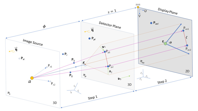
Figure 1. Geometry of X-ray Imaging from 3D to 2D. The imaging takes the form of a Cartesian system based on stereotactic space. The image source contains a plane that is parallel to the detector plane with a point source at X-ray emitter (focal spot). The focal spot generates rays (or lines) that intersect objects (fiducials) and then intersect the detector plane. The detector plane is then converted to the display plane, which is what is seen in the image. This conversion effectively transforms 3D space to 2D in Ray Tracing (RT) and Perspective Projection (PP) via Step 1 and Step 2. Keeping the entire relationship in millimeters with equal scaling (s = 1) between detector plane and display plane allows visual inspection of the relationships, which demonstrates that the scalar distance between projection objects should be the same between the detector plane and display planes. The normal of the detector plane is parallel to the normal of a plane that intersects the point source. For both RT and PP, a normalization process occurs making 3D space orthogonal to the display plane. Of note, the initial coordinate system, which could be the stereotactic coordinate system, is not Coherent On-Axis (COA) to the detector plane. In PP, a projection matrix can be generated using knowledge of 3D points (fiducials) combined with their associated position on the display plane. A non-skew PP matrix signifies that the angle (theta) is 90 degrees. Coordinates are thought of as 3D (x,y,z) in Step 1, then in Step 2 are still 3D for RT (x,y,z) or PP (u,v,t). Once images are projected on the display plane, they are 2D (U, V). The PP matrix can be used to determine the location of the point source. From the intrinsic matrix of PP, the distance between the image source and the detector plane (focal length) can be calculated, thereby allowing calculation of the detector plane location. The point on the detector plane that is closest to the focal spot can be utilized to calculate the principal point on the display plane. Finally, in the display plane, we use the top left corner of the image assigned as (0,0).


