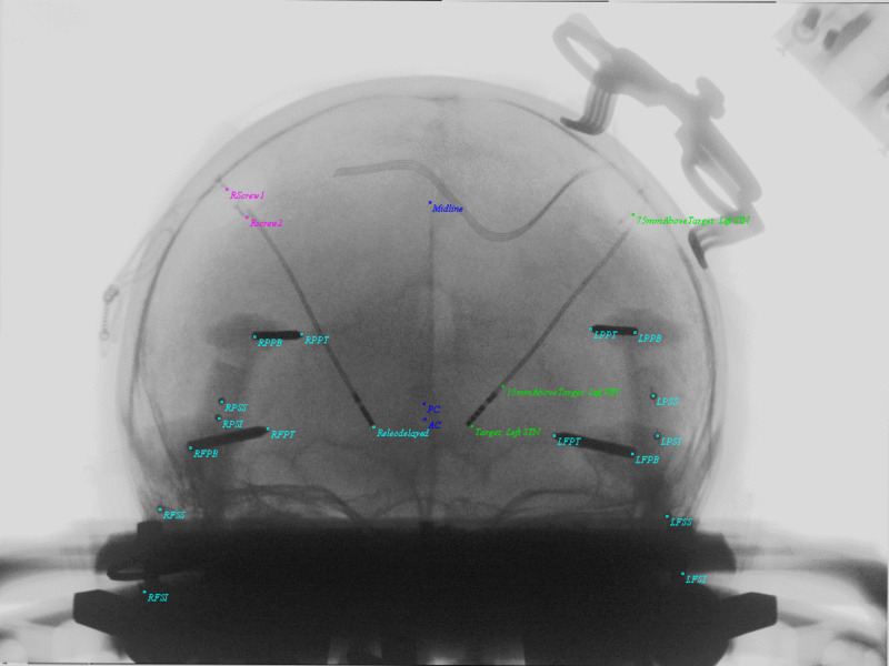
Figure 6. AP Image demonstrating the applied PP AP matrix to objects and overlap in images. Taking formula's 10-12, U (horizontal) and V (vertical) display coordinates are computed for all 3D objects and introduced into the display. Cyan colors show pin tips, pin bases, and the right DBS electrode. Screw tips from the DBS retaining cap were also included here. Anterior commissure (AC), Posterior commissure (PC), and Midline are demonstrated in blue. The left DBS electrode and original trajectory from left STN target, 15 mm above target and 75 mm above target are in green.
DBS = Deep Brain Stimulation; AP = Antero-Posterior; PP = Perspective Projection; AC = Anterior Commissure; PC = Posterior Commissure; Midline = Midline structure on Falx; Target: Left STN = Target on Left Subthalamic Nucleus; 15mmAboveTarget: Left STN = 15 millimeters above target along stereotactic axis of left subthalamic nucleus; 75mmAboveTarget: Left STN = 75 millimeters above target along stereotactic axis of left subthalamic nucleus; RPPT = Right Posterior Pin Tip; RPPB = Right POsterior Pin Base; RPSS = Right Posterior Sphere Superior; RPSI = Right Posterior Sphere Inferior; RFPT = Right Frontal Pin Tip; RFPB = Right Frontal Pin Base; RFSS = Right Frontal Sphere Superior; RFSI = Right Frontal Sphere Inferior; LPPT = Left Posterior Pin Tip; LPPB = Left Posterior Pin Base; LPSS = Left Posterior Sphere Superior; LPSI = Left Posterior Sphere Inferior; LFSS = Left Frontal Sphere Superior; LFSI = Left Frontal Sphere Inferior; LFPT = Left Frontal Pin Tip; LFPB = Left Frontal Pin Base; Relecdelayed = Right Electrode Tip; Rscrew2 = Right Screw 2; RScrew1 = Right Screw 1.

