Abstract
We demonstrate a silicon carbide (SiC) zipper photonic crystal optomechanical cavity. The device is on a 3C–SiC-on-silicon platform and has a compact footprint of ∼30 × 1 μm. The device shows an optical quality of 2800 at telecom and a mechanical quality of 9700 at 12 MHz with an effective mass of ∼3.76 pg. The optical mode and mechanical mode exhibit strong nonlinear interaction, namely, the quadratic spring effect, with a nonlinear spring constant of 3.3 × 10⁴ MHz2/nm. The SiC zipper cavity is potentially useful in sensing and metrology in harsh environments.
Silicon carbide (SiC) is well known for its exceptional thermal, mechanical, and chemical properties1 and has been widely utilized in microelectromechanical systems (MEMS) sensors,2 particularly in harsh environments3,4 and in biotechnology.5 Among its ∼250 polymorphs, 3C, 4H, and 6H are studied the most.1 3C–SiC thin films can be epitaxially grown on silicon substrates, while 4H and 6H thin films are typically grown in bulk wafer and transferred to a silicon on insulator (SOI) platform. In addition to these crystalline polymorphs, the amorphous SiC film fabricated by plasma enhanced chemical vapor deposition (PECVD) is also of interest given its low cost and convenience in growth. In the past decade, these SiC materials have been extensively explored in nanophotonics6–27 and the optical qualities of photonic devices have improved to over 105 in various platforms, including microdisks,16 double microdisks,25 and microrings24 in PECVD SiC, microrings in 3C–SiC,22 and photonic crystal cavities26 and microrings27 in 4H-SiC. Importantly, the recent advance in 4H–SiC (above in the photonic crystal cavity26 and in the integrated microring27) is particularly inspiring and has established SiC as a promising material platform.
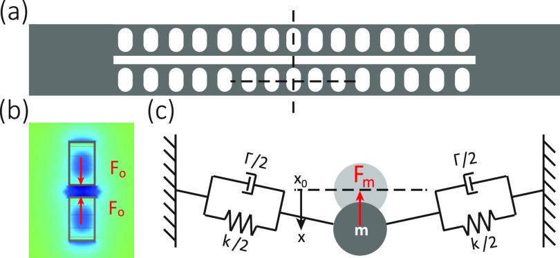
While most previous studies focus on utilizing SiC photonic structures for nonlinear optics14,15,21,26,27 and quantum optics,12,18,27 cavity optomechanics has only been explored in SiC by only a few studies to date.13,19,25 Cavity optomechanics28 confines both optical and mechanical modes in micrometer (micro-disks/rings) or nanometer (photonic crystal cavities) cavities and can potentially enhance the performance of various SiC MEMS applications.2–4 Among these cavities, the zipper photonic crystal optomechanical cavity29,30 [Fig. 1(a)] can accommodate specific sensing functionalities, using its ∼10 MHz frequency, picogram-level mass, and strong optomechanical interaction. For example, a high-resolution accelerometer has been developed on a chip based on zipper cavities31 and a gyroscope has been proposed based on zipper cavities that are coupled with disk vibrational modes.32 The zipper cavity is in analogy to the double microdisk cavity25 in that optomechanical coupling depends on the gap, rather than the dimensions of the cavity. But the zipper cavity has much better confinements both optically and mechanically than the double microdisk cavity. However, despite its usefulness, the zipper cavity has not been demonstrated in SiC yet, in part due to the requirements of geometry accuracy and straight sidewalls during nanofabrication. In contrast, many other optomechanical structures have already been demonstrated in SiC, including nanobeam cavities,13 microdisks,19 and double microdisks.25
FIG. 1.
Zipper photonic crystal optomechanical cavity. (a) Scheme of a zipper cavity. Such a cavity is a mechanical resonator and a photonic crystal cavity at the same time. The air holes are chirped and form an optical potential well to confine optical modes around the center. (b) Light confined in the optical modes exerts forces on the two nanobeams. For bonded modes, where top and bottom fields are in phase, the force is attractive. The field profile is plotted in color for fundamental transverse-electric bonded mode, simulated by finite-element methods (FEMs), in the cross section indicated by the vertical dashed line in (a). (c) A scheme shows that mechanical force is generated when one nanobeam is deformed from its stationary position, e.g., indicated by the lateral dashed line in (a).
In this paper, we demonstrate a SiC zipper photonic crystal cavity using the 3C–SiC-on-silicon platform. The device has a compact footprint of ∼30 × 1 μm. The device shows an optical quality of 2800 at a telecommunication wavelength for the fundamental transverse-electric bonded (TE1B) mode. In particular, the device has a mechanical quality of 9700 operating at 12 MHz for the fundamental differential (D1) mode with a small effective mass of ∼3.76 pg. This mechanical quality is the highest among the reported SiC optomechanical devices.13,19,25 We observe a strong nonlinear interaction between the optical mode and the mechanical mode, namely, quadratic spring softening. We attribute such a response to nanoscale geometrical nonlinearity33 and characterize the quadratic spring constant to be 3.3 × 10⁴ MHz2/nm. The demonstrated SiC zipper cavity, with its strong optomechanical interaction, tight mode confinements, mechanical robustness, and chemical stability, has great potential in microchip sensing and metrology in a harsh environment.
The zipper cavity is coupled photonic crystal cavities in optical design. Meanwhile, it is also a coupled doubly clapped nanobeam in mechanical design. The photonic crystal cavity is created by patterning the nanobeams with periodic holes. The periodicity (i.e., lattice constant) decreases harmonically toward the center of the beam to form an optical potential well for localized modes to be confined in the center.29 The two nanobeams can have fields in the same or contrary phase parities, corresponding to bonded modes or anti-bonding modes. For the bonded mode, the optical force (Fo) is attractive, as illustrated in Fig. 1(b). , where N represents the intracavity photon number and represents the optomechanical coupling constant, which can be estimated as when the geometrical coupling is in dominance. In Fig. 1(c), a scheme of the spring-mass system shows that a single doubly clamped nanobeam is oscillated in the direction along the width of the nanobeam. The other nanobeam can move in phase or out of phase to this nanobeam, namely, common or differential modes. The mechanical displacement changes the optical resonance of the mode and modulates the light inside the cavity. Therefore, the mechanical modes can be characterized by the optical transmission when being analyzed in the radio frequency spectrum.
The device is fabricated on a single-crystalline (100) 3C–SiC thin film, which is epitaxially grown using atmospheric-pressure chemical vapor deposition on a silicon wafer. The film is thinned down to (300 ± 10) nm by chemical–mechanical polishing. A 200 nm thick Chromium (Cr) is then deposited on top at a pressure of 3 mTorr as a hard mask. ZEP520A, an electron-beam resist, is spin-coated with a thickness of about 750 nm for the etching mask of Cr. This thick resist is coated in two steps and baked in between to avoid cracking. The resist is then exposed with proximity effect correction and then developed. The Cr hard mask is etched using chlorine-based reactive-ion etching (RIE). The etched patterns are then transferred to SiC by inductively coupled plasma RIE with the CF4/Ar gas mixture. The metal hard-mask is chemically removed by a Cr etcher, CR-14. Finally, the device is released by etching the underlying silicon substrate isotropically using XeF2 vapor. We note that this recipe has better verticality and resolution but worse smoothness in sidewalls compared to the aluminum oxide recipe25 and is, therefore, more suitable for photonic crystal cavities than microdisks/rings. A tapered optical fiber is used to couple the laser in and out of the device. The mechanical mode and the optomechanical interaction of the device are measured in vacuum to eliminate squeezed-film gas damping.
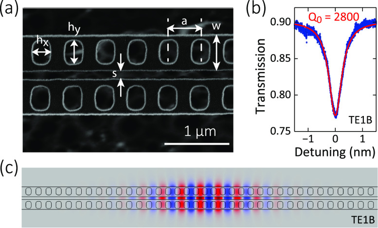
To characterize its in-plane geometry, the fabricated device is imaged by scanning-electron microscopy from top, as shown in Fig. 2(a). The parameters are labeled in the image. For a device with a lattice constant of a = 540 nm, a beam width of w = 530 nm, and a slot gap of s = 130 nm, Fig. 2(b) shows the measured transmission spectrum of the fundamental bonded mode (TE1B), which exhibits an intrinsic Q-factor of 2800 at a resonance wavelength of 1483 nm. Figure 3(c) shows the FEM-calculated mode profile of TE1B with a mode volume of 0.084 and the mode is largely confined in the gap. Using a near-field probing technique,29 we identify the mode parity by the scattering of the optical modes.
FIG. 2.
Optical characterization of the SiC zipper cavity. (a) Top-view scanning electron microscope (SEM) images of a SiC zipper photonic crystal cavity. Besides the thickness th, other important parameters are labeled in the image, including the lattice constant (a), the beam width (w), the slot width (s), and the widths of the air holes (). (b) Optical transmissions of the fundamental transverse-electric bonded mode (TE1B) at 1483 nm, with a Lorentzian fitting of intrinsic Q of 2800. (c) Dominant (in plane) electric field profile of the TE1B mode simulated by finite element methods.
FIG. 3.
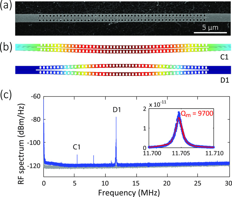
Mechanical characterization of the SiC zipper cavity. (a) Scanning electron microscopy image of the whole nanobeam. (b) Mechanical displacement of the in-plane fundamental common (C1) and fundamental differential (D1) modes, simulated by finite element methods. The mode at 8 MHz might be a common mode in the vertical direction, but bears further investigation. (c) Measured radio frequency spectrum of the zipper cavity in the optical transmission shows the thermal Brownian motion of the mechanical modes. Detector noise floor is displaced in gray. The inset shows a zoom-in spectrum of the D1 mode and the fitting of a mechanical Q of 9700.
We have also fabricated single nanobeam cavity with the same parameters for a comparison with the zipper cavity. With appropriate lattice constants, the single nanobeam can have optical resonances in the laser tuning range (1470 nm–1545 nm). For a lattice constant of a = 580 nm and a beam width of w = 540 nm, we measure the fundamental mode (TE1B) at 1496 nm, which exhibits an intrinsic optical quality factor of Qo ≈ 2900. In simulation, such a nanobeam photonic crystal cavity has a radiation-limited Q-factor of up to 2 × 10⁶, which suggests that the measured Q is likely limited by the scattering loss from the sidewall roughness. The nanobeam cavity has an effective volume of 0.049 .
The zipper cavity supports two types of mechanical modes: common modes and differential modes. For example, Fig. 3(b) illustrates mechanical modes of the fundamental common (C1) and fundamental differential (D1) mechanical modes, simulated by finite element methods. Because the clamping position is different, as shown in Fig. 3(a), C1 mode has an effectively longer beam length and, therefore, exhibits a smaller mechanical frequency than D1 mode.
Thanks to the strong optomechanical coupling, the thermal-Brownian mechanical motion can be directly observed by continuous-wave light. By locking the laser wavelength at the side of optical resonance, the thermal Brownian motion is translated into the fluctuation of transmitted light. We measure the optical transmission using a fast photodetector and analyze its radio frequency spectrum, as shown in Fig. 3(c).
We identify C1 and D1 modes using the FEM calculations with a Young's modulus of 390 GPa and a Poisson's ratio of 0.17, previously verified for 3C–SiC.19 Compared to C1 mode, D1 mode exhibits a much larger signal because of its higher optomechanical coupling rate. For the D1 mode, we fit the resonance amplitude with the Lorentzian function and obtain a mechanical quality factor Qm of 9700 in vacuum. The pressure is ≈ 10–5 Torr, and Qm is not sensitive to pressure at this pressure level. In air, the mechanical damping is dominated by the squeeze film and air damping and has Qm = 42.
Conventionally, cavity optomechanics has a linear response between the light and the mechanical spring, which is known as the linear optical (LO) spring effect.28 The frequency shift of the mechanical spring linearly depends on the optical power. The frequency shift is given by
| (1) |
where , and represent the intracavity photon number, reduced Planck constant, and optomechanical coupling strength, respectively. Δ is the laser-cavity detuning, and a positive/negative Δ represents a blue-/red-detuning laser. represents the loaded cavity linewidth, which is given by , where is the optical frequency and is the loaded cavity quality factor. is the effective mass. is the natural mechanical frequency. This spring effect has two signature features. First, the mechanical frequency shift is zero at zero-detuning. Second, the spring is hardened (an increase in frequency) when blue-detuned (Δ > 0) and softened (a decrease in frequency) when red-detuned (Δ < 0).
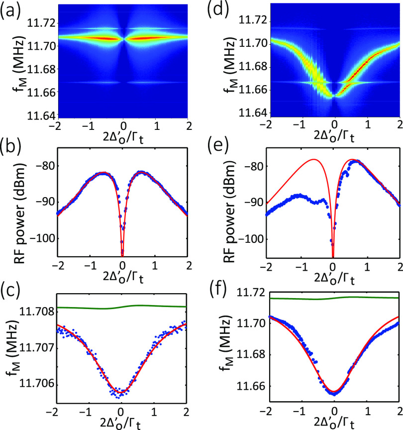
Figure 4 shows the measured radio frequency spectra in different laser-cavity detuning with TE1B cavity resonance. In contrast to linear optomechanics predicted by Eq. (1), the frequency shift is maximal (and nonzero) at zero-detuning; the spring is always softened for both blue-detuned and red-detuned cases, as shown in Fig. 4(c). Indeed, the spring softening (i.e., decrease in frequency) is the largest when detuning is 0. We note that the spring softening/hardening is comparable to original frequency without light input (or the laser is off resonance). Here, we only input a small amount of optical power = 14 W. This power level corresponds to only about 70 photons in the cavity on average. We observe that D1 mode shifts to the lower frequency by = −2.3 kHz at zero-detuning. For higher optical input power ( = 224 μW) as shown in Figs. 4(d)–4(f), a larger mechanical resonance shift is observed with = −60 kHz.
FIG. 4.
Optomechanical coupled mechanical nonlinearity. (a) and (d) Intensity images of the measured radio frequency spectra of the D1 mechanical mode as a function of laser-cavity detuning. (b) and (e) Measured and modeled RF amplitude as a function of cavity detuning. At zero detuning, the signal vanishes because there is no optomechanical transduction (the derivative of Lorentzian is zero). At large detuning, the signal vanishes because light is not coupled into the cavity. The asymmetric experimental data in (e) are due to the thermal bistability created by higher optical power, which are not considered in our theory. (c) and (f) Measured and modeled mechanical frequency as a function of cavity detuning. (a)–(c) correspond to low optical input power (Pi = 14 μW). (d)–(f) correspond to high optical input power (Pi = 224 μW). Blue dots are the measured data. Red curves are the model fitting results with mechanical nonlinearity. Green curves are the calculation results with the optical spring effect. Red dotted lines are the calculated thermal amplitude at T = 300K.
The softening of the mechanical resonance is likely due to the nanoscale geometric nonlinearity, which was previously reported in a doubly clamped cantilever nanotube system,33 where the high-order spring constant is more dominant in the system that is asymmetric and on the nanoscale. The loaded mechanical frequency () has a frequency shift () from the nature frequency () due to the geometric nonlinearity and also the LO spring effect,
| (2) |
Here, the first term represents the natural mechanical frequency, the second term is related to the frequency shift due to the second-order mechanical nonlinearity induced by the optical force, the third them is related to the frequency shift due to the Duffing parameter (α), and the last term is the optical spring effect induced by linear optomechanical coupling, where is given previously. x0 represents the static mechanical displacement induced by the intracavity optical power, given by By fitting the optical transduction power of the mechanical modes, as shown in Figs. 4(b) and 4(e), we obtain a linear optomechanical coupling coefficient of 17 GHz/nm for the D1 mode. This value is consistent with the FEM-calculated value, that is, 20 GHz/nm for a device gap of s = 130 nm. In Figs. 4(c) and 4(f), the red curves indicate the model fitting of the mechanical resonance shift with MHz2/nm. The nonlinear spring constant is, therefore, = 0.14 nN/nm2. The nonlinear spring effect is very large and dominates over the linear optical spring effect. For reference, we show the calculated resonance shift contributed by the optical spring effect [calculated from Eq. (1)] by green curves.
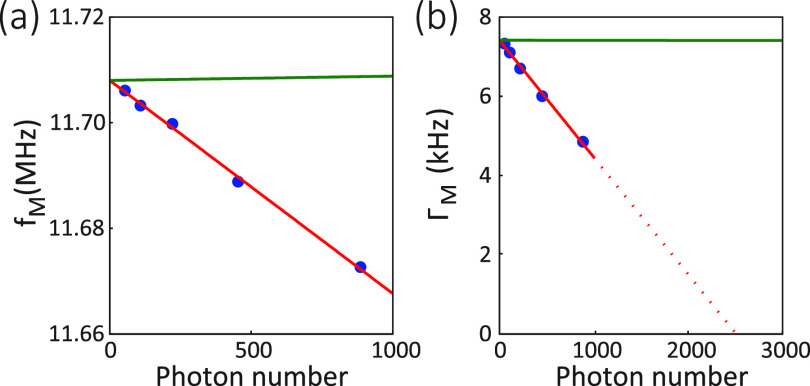
Figure 5 shows the power-dependent measurement of the frequency and linewidth tuning of the mechanical resonance. Each measurement data point is taken at the optimal detuning point of . We avoid the red-detuning side () where detuning suffers from resonance jitter due to the thermal-refractive effect, as shown in Figs. 4(a) and 4(b). In Fig. 5(a), the softening of the mechanical resonance linearly depends on intracavity photon number . The red curve shows the model fitting with MHz2/nm. Note that the Duffing nonlinear term (α = 0) is not observed because the quadratic contribution is negligible. In Fig. 5(b), the linewidth narrowing of the mechanical resonance scales linearly with the photon number. We attribute the linewidth tuning to the mechanical damping nonlinearity, where the renormalized mechanical damping () is given by
| (3) |
FIG. 5.
Nonlinear mechanical spring and damping. Renormalized mechanical frequency (a) and mechanical linewidth (b) as a function of intracavity photon number. Blue dots are the measured data at the optimal detuning (in terms of maximum optical transduction) of . Red curves are the model fitting with (MHz)2/nm and ζ = 5.2 MHz/nm (). Green curves are the calculated results with the optical spring effect (a) and dynamic backaction (b).
Here, the last term represents dynamic back-action from linear optomechanical interaction.28 The model fitting (red curve) shows the first-order coefficient of nonlinear damping, ζ = 5.2 MHz/nm, suggesting the amplification of mechanical motion. In this case, second-order nonlinear damping (η) is not observed. The red dashed line shows the threshold of the parametric amplification at . Green curves show the contribution from linear optomechanical coupling, i.e., optical spring effect and dynamic back-action, which are again negligible. The mechanical nonlinearity overtakes the linear optomechanical effects, and such a strong nonlinear response can find application in sensing and metrology.
In this Letter, we demonstrate a 3C–SiC zipper photonic crystal optomechanical cavity with a high mechanical quality of 9700 and a large quadratic spring softening effect. The demonstrated SiC zipper cavity is potentially useful for sensing in a harsh environment.2,4,34 In particular, the zipper cavity is not suitable for operation that requires both a high mechanical Q factor and an ambient environment at the same time. It is suitable for chemical/particle sensing under low pressure or motion sensing with vacuum packaging at high temperature.
Acknowledgments
This work was supported in part by NSF Nos. EFMA-1641099, ECCS-1610674, ECCS-1509749, and ECCS-1408517 and by NIH No. R21EB0249988. The device fabrication was performed at the Cornell NanoScale Science & Technology Facility (CNF).
Contributor Information
Xiyuan Lu, Email: .
Qiang Lin, Email: .
DATA AVALABILITY
The data that support the plots within this paper and other findings of this study are available from the corresponding authors upon reasonable request.
References
- 1. Harris G. L., Properties of Silicon Carbide ( INSPEC, 1995). [Google Scholar]
- 2. Wright N. G. and Horsfall A. B., “ SiC sensors: A review,” J. Phys. D: Appl. Phys. 40, 6345–6354 (2007). 10.1088/0022-3727/40/20/S17 [DOI] [Google Scholar]
- 3. Mehregany M., Zorman C. A., Rajan N., and Wu C. H., “ Silicon carbide MEMS for harsh environments,” Proc. IEEE 86, 1594–1609 (1998). 10.1109/5.704265 [DOI] [Google Scholar]
- 4. Senesky D. G., Jamshidi B., Cheng K. B., and Pisano A. P., “ Harsh environment silicon carbide sensors for health and performance monitoring of aerospace systems: A review,” IEEE Sens. J. 9, 1472–1478 (2009). 10.1109/JSEN.2009.2026996 [DOI] [Google Scholar]
- 5. Saddow S. E., Silicon Carbide Biotechnology, 2nd ed. ( Elsevier, 2016). [Google Scholar]
- 6. Song B.-S., Yamada S., Asano T., and Noda S., “ Demonstration of two-dimensional photonic crystals based on silicon carbide,” Opt. Express 19, 11084–11089 (2011). 10.1364/OE.19.011084 [DOI] [PubMed] [Google Scholar]
- 7. Yamada S., Song B.-S., Upham J., Asano T., Tanaka Y., and Noda S., “ Suppression of multiple photon absorption in a SiC photonic crystal nanocavity operating at 1.55 μm,” Opt. Express 20, 14789–14796 (2012). 10.1364/OE.20.014789 [DOI] [PubMed] [Google Scholar]
- 8. Cardenas J., Zhang M., Phare C. T., Shah S. Y., Poitras C. B., Guha B., and Lipson M., “ High Q SiC microresonators,” Opt. Express 21, 16882–16887 (2013). 10.1364/OE.21.016882 [DOI] [PubMed] [Google Scholar]
- 9. Radulaski M., Babinec T. M., Buckley S., Rundquist A., Provine J., Alassaad K., Ferro G., and Vučković J., “ Photonic crystal cavities in cubic (3C) polytype silicon carbide films,” Opt. Express 21, 32623–32629 (2013). 10.1364/OE.21.032623 [DOI] [PubMed] [Google Scholar]
- 10. Lu X., Lee J. Y., Feng P. X.-L., and Lin Q., “ Silicon carbide microdisk resonator,” Opt. Lett. 38, 1304–1306 (2013). 10.1364/OL.38.001304 [DOI] [PubMed] [Google Scholar]
- 11. Magyar A. P., Bracher D., Lee J. C., Aharonovich I., and Hu E. L., “ High quality SiC microdisk resonators fabricated from monolithic epilayer wafers,” Appl. Phys. Lett. 104, 051109 (2014). 10.1063/1.4863932 [DOI] [Google Scholar]
- 12. Calusine G., Politi A., and Awschalom D. D., “ Silicon carbide photonic crystal cavities with integrated color centers,” Appl. Phys. Lett. 105, 011123 (2014). 10.1063/1.4890083 [DOI] [Google Scholar]
- 13. Lee J. Y., Lu X., Feng P. X.-L., and Lin Q., “ 3C-SiC nanobeam optomechanical crystals,” in CLEO ( Optical Society of America, 2014). [Google Scholar]
- 14. Yamada S., Song B.-S., Jeon S., Upham J., Tanaka Y., Asano T., and Noda S., “ Second-harmonic generation in a silicon-carbide-based photonic crystal nanocavity,” Opt. Lett. 39, 1768–1771 (2014). 10.1364/OL.39.001768 [DOI] [PubMed] [Google Scholar]
- 15. Lu X., Lee J. Y., Feng P. X., and Lin Q., “ High Q silicon carbide microdisk resonator,” Appl. Phys. Lett. 104, 181103 (2014). 10.1063/1.4875707 [DOI] [Google Scholar]
- 16. Lu X., Lee J. Y., Rogers S., and Lin Q., “ Optical Kerr nonlinearity in a high-Q silicon carbide microresonator,” Opt. Express 22, 30826–30832 (2014). 10.1364/OE.22.030826 [DOI] [PubMed] [Google Scholar]
- 17. Lee J. Y., Lu X., and Lin Q., “ High-Q silicon carbide photonic-crystal cavities,” Appl. Phys. Lett. 106, 041106 (2015). 10.1063/1.4906923 [DOI] [PMC free article] [PubMed] [Google Scholar]
- 18. Radulaski M., Babinec T. M., Müller K., Lagoudakis K. G., Zhang J. L., Buckley S., Kelaita Y. A., Alassaad K., Ferro G., and Vučković J., “ Visible photoluminescence from cubic (3C) silicon carbide microdisks coupled to high quality whispering gallery modes,” ACS Photonics 2, 14–19 (2015). 10.1021/ph500384p [DOI] [Google Scholar]
- 19. Lu X., Lee J. Y., and Lin Q., “ High-frequency and high-quality silicon carbide optomechanical microresonators,” Sci. Rep. 5, 17005 (2015). 10.1038/srep17005 [DOI] [PMC free article] [PubMed] [Google Scholar]
- 20. Lee J., Zamani H., Rajgopal S., Zorman C. A., and Feng P. X.-L., “ 3C-SiC microdisk mechanical resonators with multimode resonances at radio frequencies,” J. Micromech. Microeng. 27, 074001 (2017). 10.1088/1361-6439/aa6ab7 [DOI] [Google Scholar]
- 21. Martini F. and Politi A., “ Four wave mixing in 3C SiC ring resonators,” Appl. Phys. Lett. 112, 251110 (2018). 10.1063/1.5034456 [DOI] [Google Scholar]
- 22. Fan T., Moradinejad H., Wu X., Eftekhar A. A., and Adibi A., “ High-Q integrated photonic microresonators on 3C-SiC-on-insulator (SiCOI) platform,” Opt. Express 26, 25814–25826 (2018). 10.1364/OE.26.025814 [DOI] [PubMed] [Google Scholar]
- 23. Zheng Y., Pu M., Yi A., Chang B., You T., Huang K., Kamel A. N., Henriksen M. R., Jrgensen A. A., Ou X., and Ou H., “ High-quality factor, high-confinement microring resonators in 4H-silicon carbide-on-insulator,” Opt. Express 27, 13053–13060 (2019). 10.1364/OE.27.013053 [DOI] [PubMed] [Google Scholar]
- 24. Xing P., Ma D., Ooi K. J. A., Choi J. W., Agarwal A. M., and Tan D., “ CMOS-compatible PECVD silicon carbide platform for linear and nonlinear optics,” ACS Photonics 6, 1162–1167 (2019). 10.1021/acsphotonics.8b01468 [DOI] [Google Scholar]
- 25. Lu X., Lee J. Y., Rogers S. D., and Lin Q., “ Silicon carbide double-microdisk resonator,” Opt. Lett. 44, 4295–4298 (2019). 10.1364/OL.44.004295 [DOI] [PubMed] [Google Scholar]
- 26. Song B.-S., Asano T., Jeon S., Kim H., Chen C., Kang D. D., and Noda S., “ Ultrahigh-Q photonic crystal nanocavities based on 4H silicon carbide,” Optica 6, 991–995 (2019). 10.1364/OPTICA.6.000991 [DOI] [Google Scholar]
- 27. Lukin D. M., Dory C., Guidry M. A., Yang K. Y., Mishra S. D., Trivedi R., Radulaski M., Sun S., Vercruysse D., Ahn G. H., and Vučković J., “ 4H-silicon-carbide-on-insulator for integrated quantum and nonlinear photonics,” Nat. Photonics 14, 330–334 (2020). 10.1038/s41566-019-0556-6 [DOI] [Google Scholar]
- 28. Aspelmeyer M., Kippenberg T. J., and Marquardt F., “ Cavity optomechanics,” Rev. Mod. Phys. 86, 1391–1452 (2014). 10.1103/RevModPhys.86.1391 [DOI] [Google Scholar]
- 29. Chan J., Eichenfield M., Camacho R., and Painter O., “ Optical and mechanical design of a “zipper” photonic crystal optomechanical cavity,” Opt. Express 17, 3802–3817 (2009). 10.1364/OE.17.003802 [DOI] [PubMed] [Google Scholar]
- 30. Grutter K. E., Davanço M. I., and Srinivasan K., “ Slot-mode optomechanical crystals: A versatile platform for multimode optomechanics,” Optica 2, 994–1001 (2015). 10.1364/OPTICA.2.000994 [DOI] [PMC free article] [PubMed] [Google Scholar]
- 31. Krause A. G., Winger M., Blasius T. D., Lin Q., and Painter O., “ A high-resolution microchip optomechanical accelerometer,” Nat. Photonics 6, 768–772 (2012). 10.1038/nphoton.2012.245 [DOI] [Google Scholar]
- 32. Lee J. Y., Lin Q., and Painter O., “ Optomechanical disk vibratory gyroscopes,” U.S. patent 20160069686 (2016).
- 33. Cho H., Jeong B., Yu M.-F., Vakakis A. F., McFarland D. M., and Bergman L. A., “ Nonlinear hardening and softening resonances in micromechanical cantilever-nanotube systems originated from nanoscale geometric nonlinearities,” Int. J. Solids Struct. 49, 2059–2065 (2012). 10.1016/j.ijsolstr.2012.04.016 [DOI] [Google Scholar]
- 34. Qiao Q., Xia J., Lee C., and Zhou G., “ Applications of photonic crystal nanobeam cavities for sensing,” Micromachines 9, 541 (2018). 10.3390/mi9110541 [DOI] [PMC free article] [PubMed] [Google Scholar]
Associated Data
This section collects any data citations, data availability statements, or supplementary materials included in this article.
Data Availability Statement
The data that support the plots within this paper and other findings of this study are available from the corresponding authors upon reasonable request.


